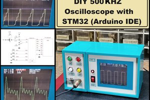
mircemk
The VTTC Staccato Controller was developed in the attempt to create longer sparks from VTTCs while at the same time reducing the input power. The Staccato Controller achieves this by operating the VTTC for a full AC half cycle, then disabling the VTTC for a selectable number of AC half cycles. Basically the controller consists of an oscillator with adjustable parameters and a triac or thyristor at the output of the oscillator, which is connected between the cathode of the vacuum tube and ground.
In the device that I will present to you in this video, an Arduino Nano board is used to build the oscillator, so the device is very simple to build, and yet has many control options. The presented code is very simple and understandable, so if we have some experience in programming, we can expand these possibilities. The original project was taken from teslamuuntaja's blog and I added a two-transistor part so now Mosfet SSTC can also be controlled.
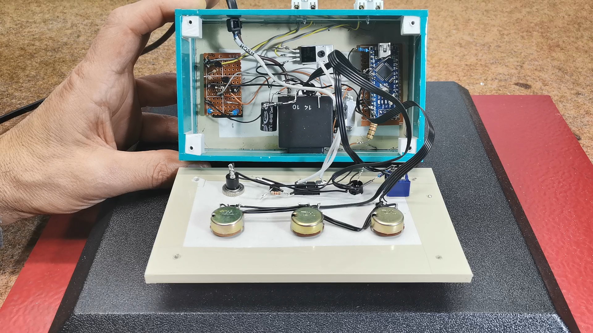
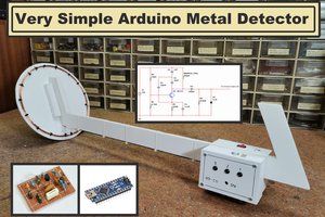
The device is composed of several parts:
- Arduino Nano MCU board
- Three control potentiometers
- Mains transformer with 12V output
- Gretz junction with filter capacitor and voltage stabilizer
- Triac through which VTTC is controlled
- Two transistors for control of SSTC
- and some diodes and resistors
This project is sponsored by PCBWay. They has all the services you need to create your project at the best price, whether is a scool project, or complex professional project. On PCBWay you can share your experiences, or get inspiration for your next project. They also provide completed Surface mount SMT PCB assemblY service at a best price, and ISO9001 quality control. Visit www.pcbway.com for more services.

Now let's briefly explain the working principle. There is a full-wave rectifier on the secondary of the mains transformer, in the continuation of which there is a filter electrolytic capacitor and a voltage stabilizer for 12V. This voltage is used to power the Arduino board. Between the transformer and the rectifier bridge, a half-wave rectified current is taken via a diode to a voltage divider, consisting of two 1 kΩ resistors. After the voltage divider, there is a 100 nF capacitor for filtering, followed by a 4.7-volt Zener diode to limit the voltage to Arduino's maximum of 5 volts. The resulting half-wave rectified and 4.7-volt limited voltage is fed into Arduino's analog input A1. Using this signal, Arduino controls the triac and two tyransistor circuit part, which is triggered from Arduino's output D12 through a 220 Ω resistor.
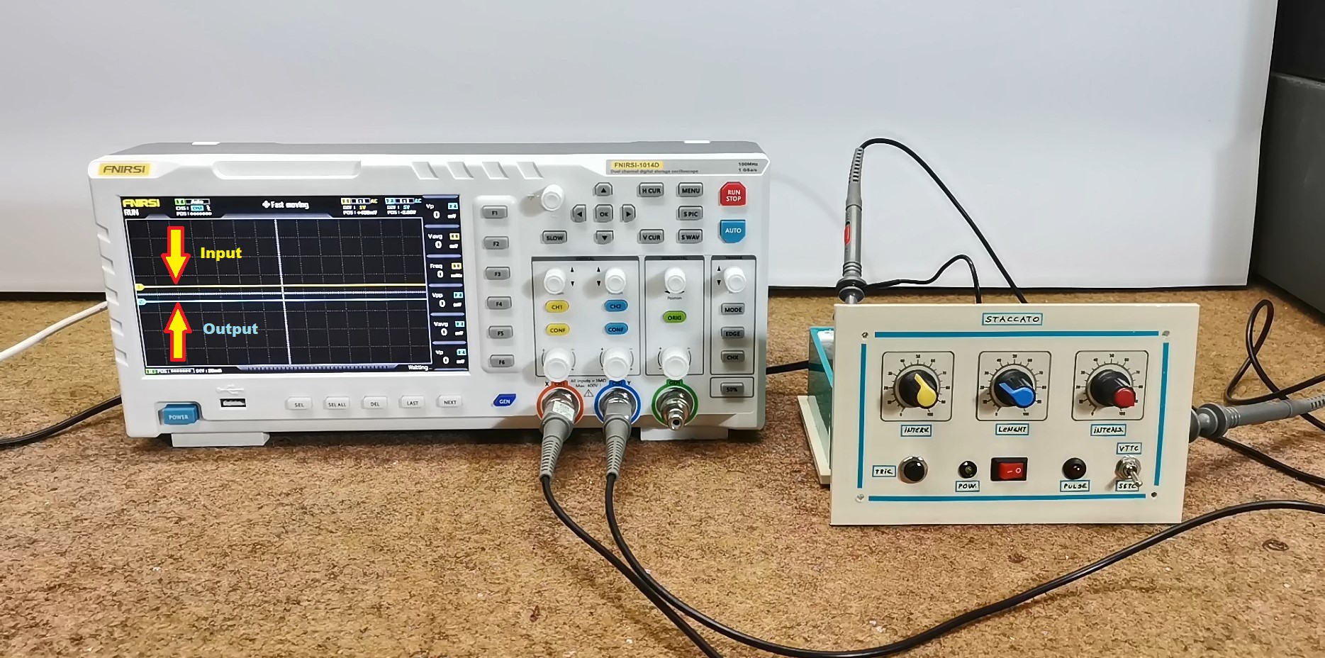
To Arduino analog inputs A2, A3, and A4 are connected three potentiometers that regulate the interval, length and intensity of the generated signal. A button is connected to the D2 pin with pull up resistor. By using the push button, a single trigger can be given. If potentiometer R2 is adjusted to a point where the device does not provide pulses, the push button can be used to give one pulse at a time. LED diode flashes in sync with the triac trigger pulses.

On the back of the device there are two terminals to which the appropriate type of Tesla transformer should be connected, previously selected with the switch. The negative pole in both cases need to be connected to the ground, and the positive pole on VTTC is connected to the cathode of the vacuum tube, while in the SSTC to the Gate of the Mosfet or to the input of the Mosfet driver.
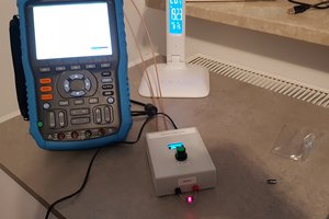
We can best capture the way the device works with the help of an oscilloscope. For this purpose, we connect one channel of the oscilloscope to pin A1, which is the input, and the other channel to the output pin D12. The oscilloscope provides a clear visual demonstration of how all adjustment works. In the oscilloscope image, you can see the half-waves of the mains current in yellow and the triggering pulses of the triac in blue.
...
Read more »
 Przemo Wodz