 Morning.Star
These are parts of AIME's operating system that I am beginning to shoe-horn into a Raspberry Pi or more probably a few Zero's networked together inside a smaller and less sophisticated quadruped. AIME was 3.2GHz dual-core intel powered and a lot more complex so it's a lot of work, and I have many interests that I've never managed to reconcile in one place. Robotics probably comes closest, but I think it would take a lottery win to get me that secret laboratory I've dreamed of for decades.
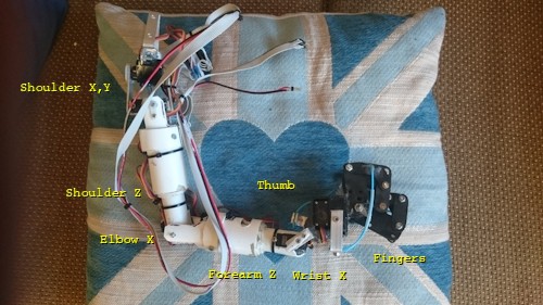
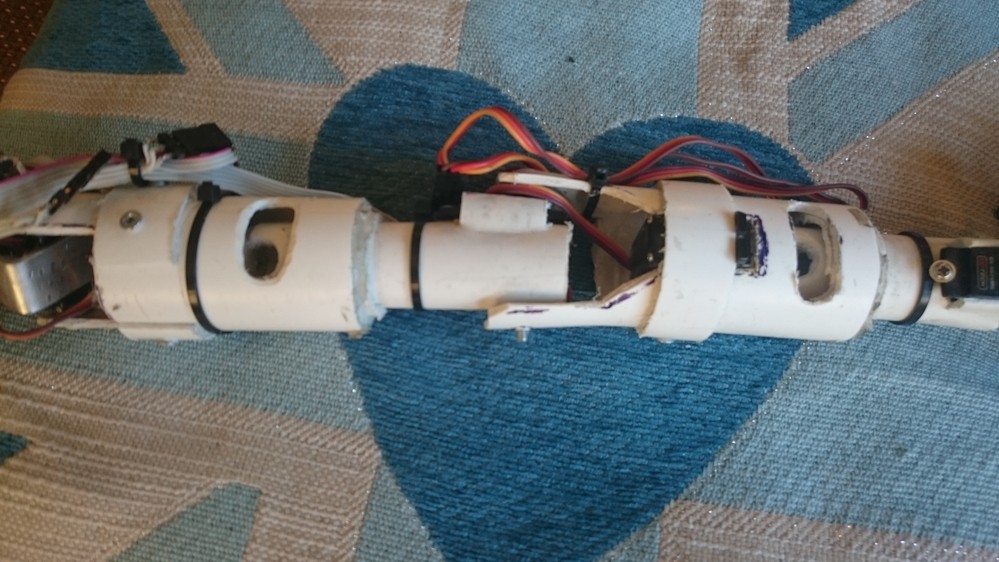
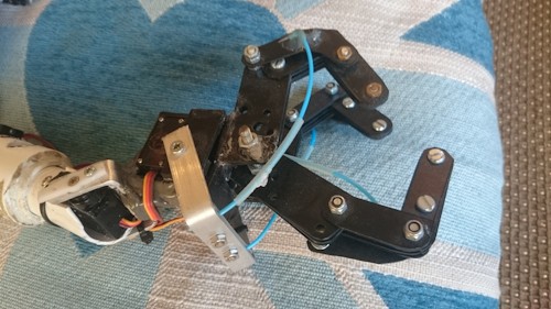
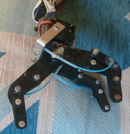
AIME had two Arduinos, one to control each arm (8 servos) and leg (3 servos) and head (2 servos, one Arduino for X, the other for Y), and a pair of cameras.
The Quad
This is the Quad. Its got a frozen servo I'll have to swap out when I have time and it needs a board with a couple of ULN2804a (6v) drivers and some Darlingtons. Ive just unboxed it to post for now but it is nearly ready to go and has been for a few years.
It doesnt have a name yet. Anyone? :-)
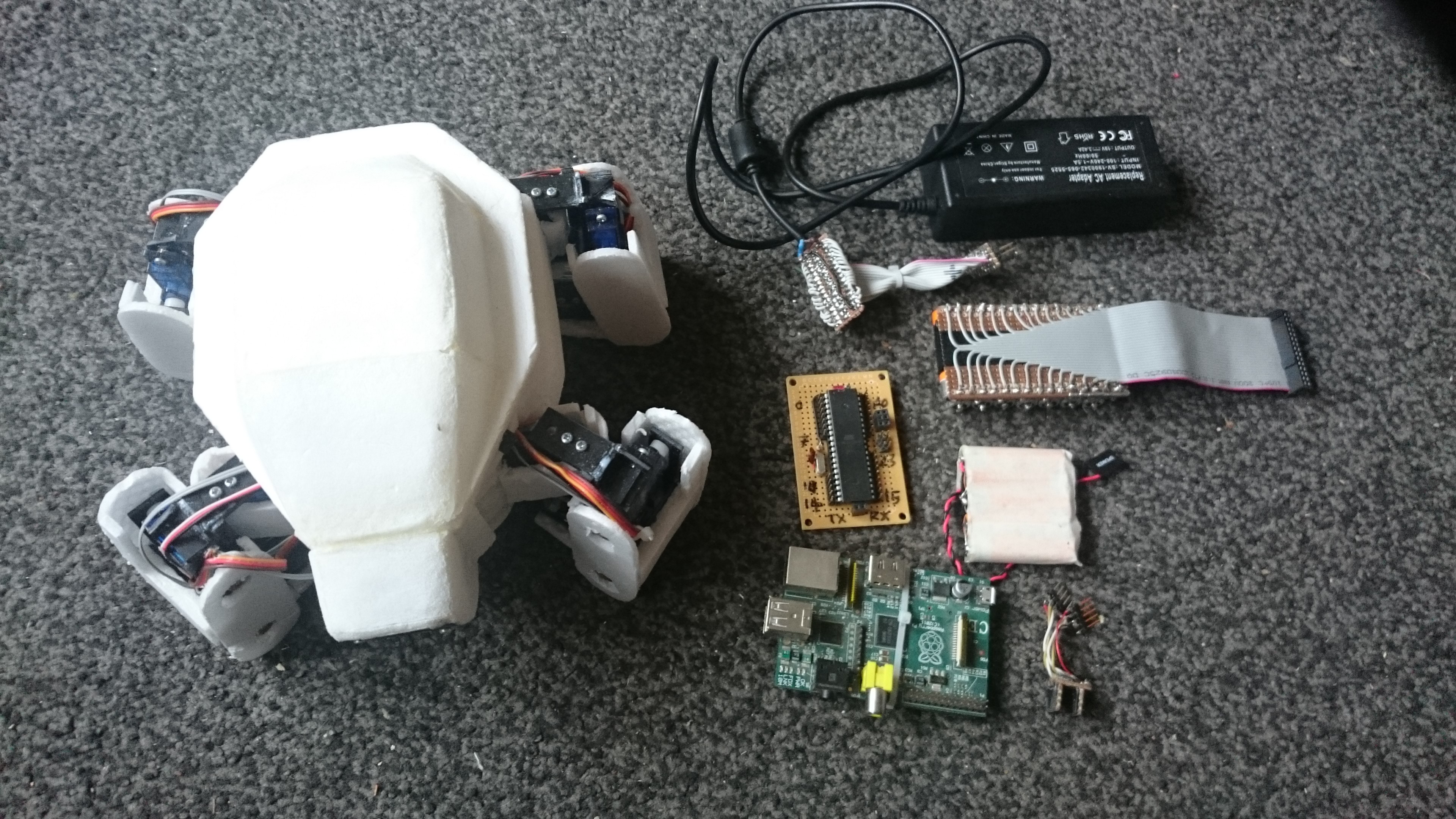
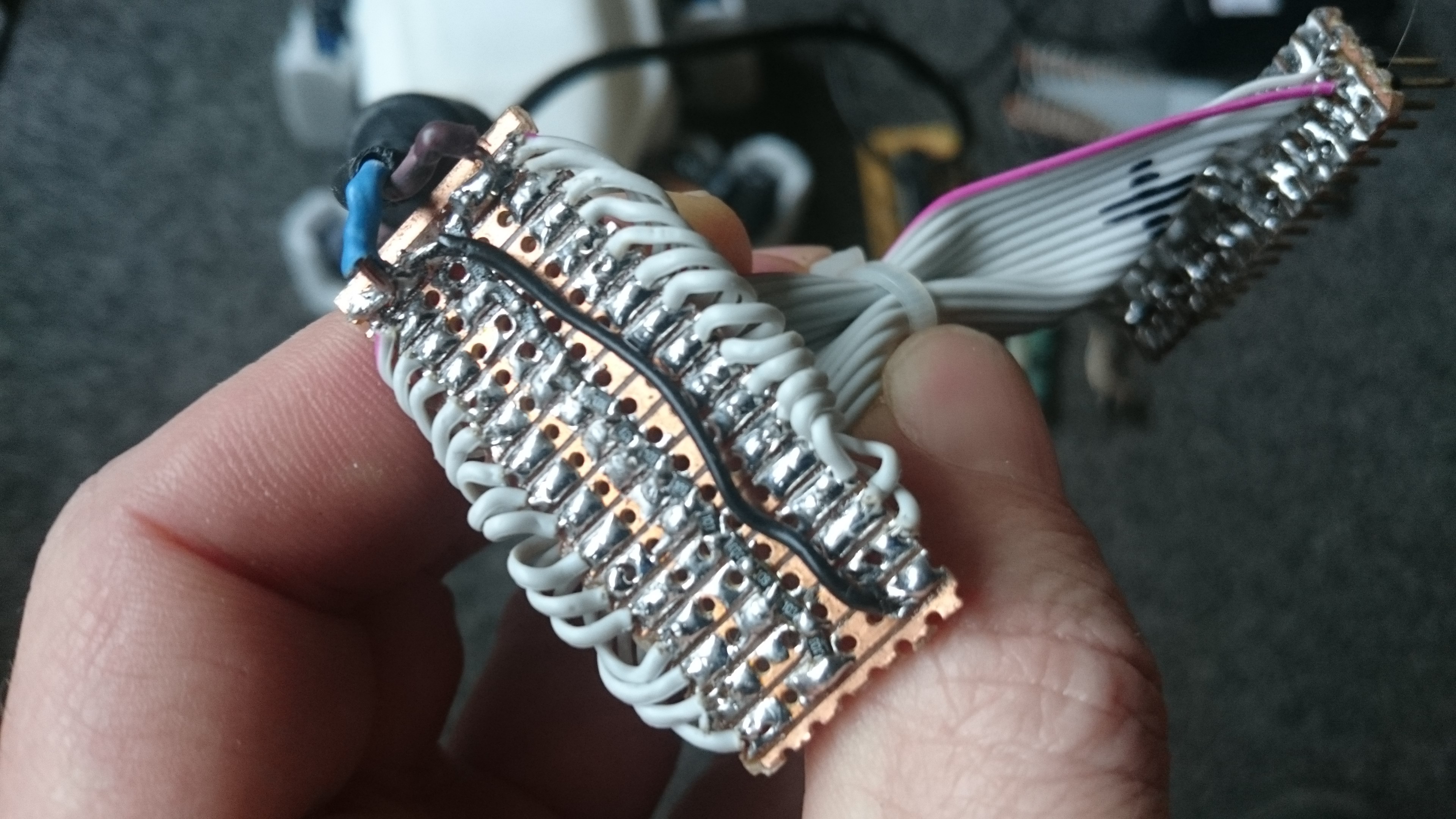
Thats an ATMega1284PPU. I'm using the extra pins to multiplex the batteries, which is the reason for the wide power bus. There's 13 servos and most of the weight is on four of them. They run on 6v, powered by 15 1.2v NIMH batteries so I decided to implement bank management, and feed the hungry servos off the best cells using a slow average. The Pi and Mega have their own separate bank to power the brain that will still outlast the main cells.
The main power bank is charged with a 19v supply in parallel using a resistive ladder. It takes a while but it gets there in the end.
One of the first things my mill is going to do, is cut protoboard for these horrible SMD components. My idea is an axonometric grid of round pads joined together by a grid of traces I can cut and drop a component over, or isolate a line of them for a track. When I have the funds, I think I'll get OSHPark to make me some pretty ones for this.
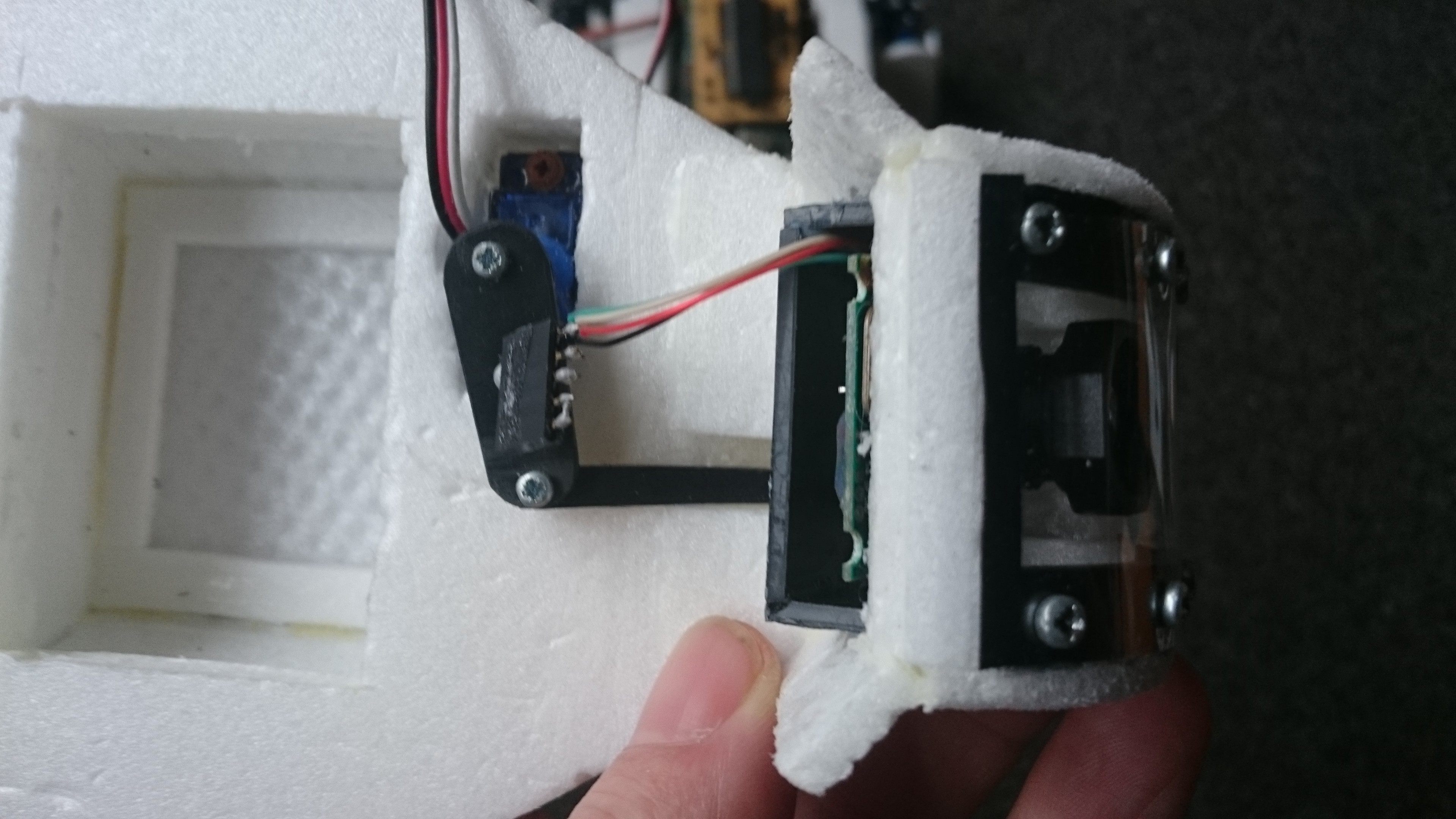
Here's the 13th servo, it tilts the camera up and down.
The entire thing is built out of pizza rounds, each layer cut to shape with a scalpel and glued together, then finished with sandpaper. When someone manages to build a 3D printer that can print this stuff, let me know. WOOT...
The chassis is polycarbonate sheet bonded with accelerated superglue. I cut it with a scalpel and protractor to score the shapes I need for each part, then snap them up and glue them together. Its fast, accurate, clean, and leaves very little waste. The entire robot came out of a single piece a bit bigger than an A4 card. It costs a few quid/bucks a sheet, and is very strong for it's weight.
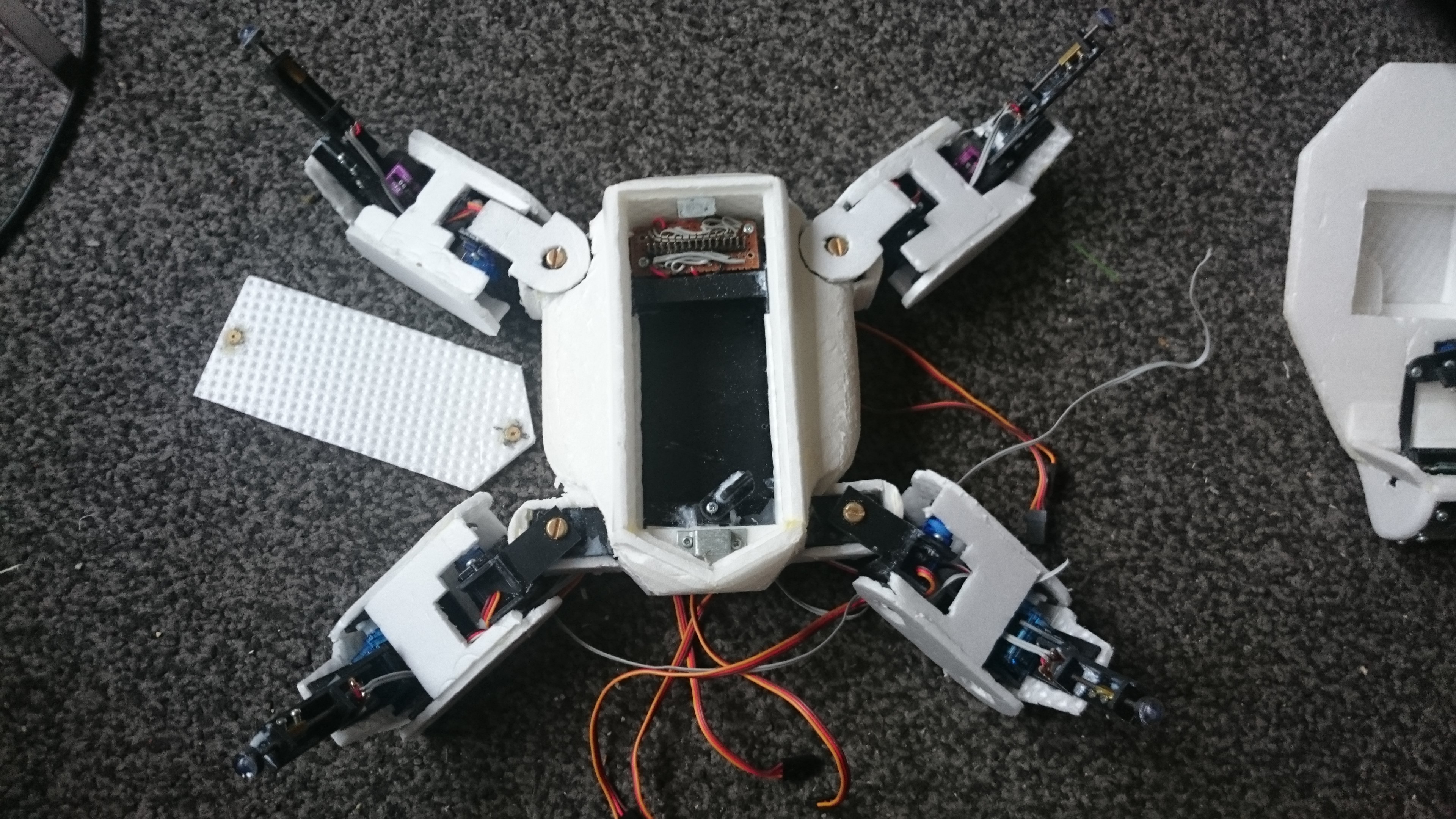
Once I built the chassis I dropped the shell around it and glued the two halves together. The battery hatch is secured by little magnets glued into recesses, the lid will be the same.
The feet have sensors connected to the Analog Inputs on the Mega. The controller will sample these at a decent rate to get an idea of what surface it is walking on, and I intend to build in behaviours like investigating things with an exploratory poke.
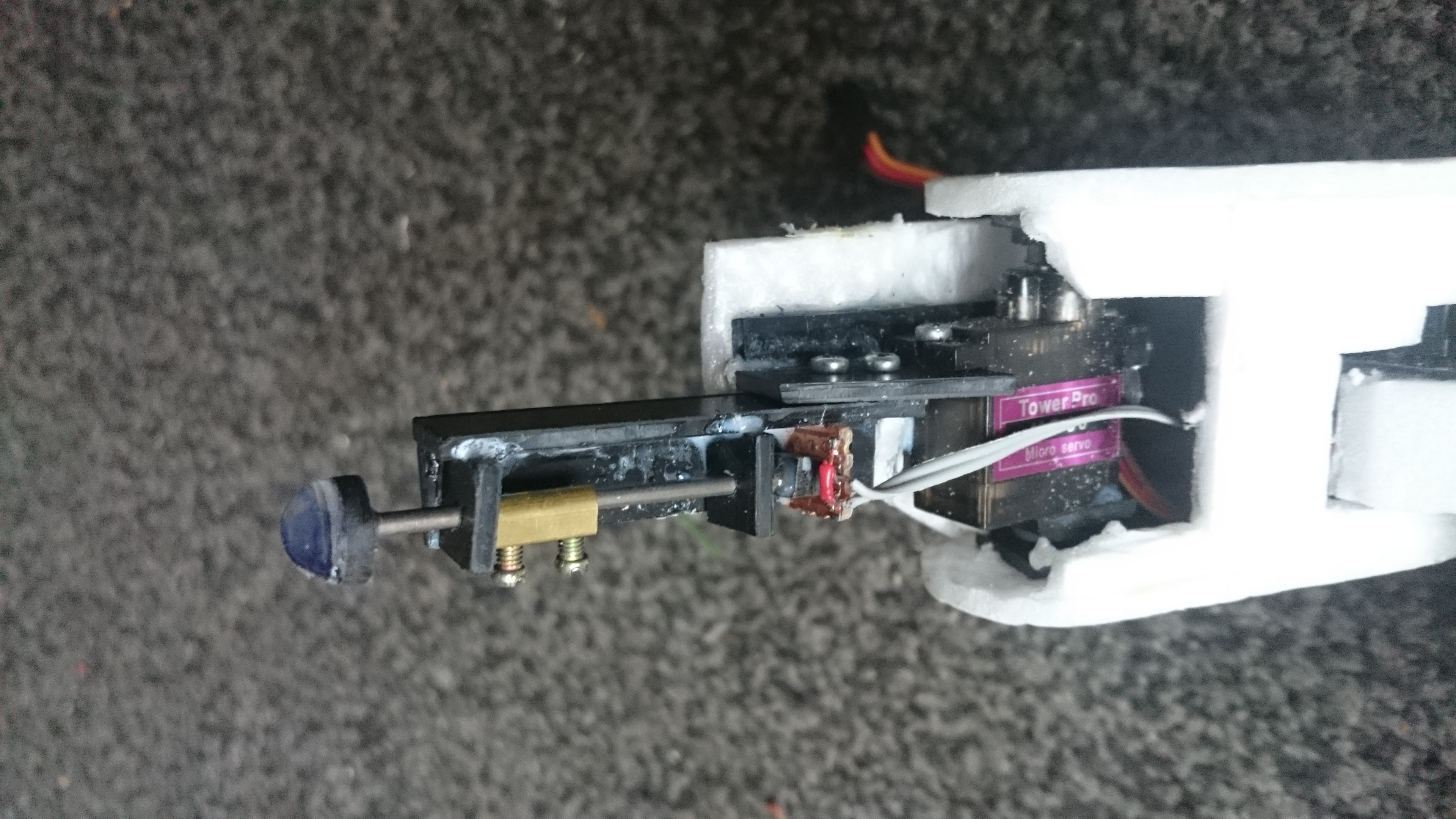
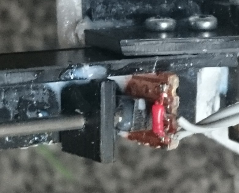
In there is a piston compressing a pressure sensitive polymer against two tracks of a bit of Veroboard. I was too lazy to etch 4 pads... The polymer is a QTC Pill - Quantum Tunnelling Compound, an amazing invention. Its a non conductive polymer rubber until you apply pressure to it, then it responds with a fairly linear decrease in resistance down to a few KOhms before material failure. It's in remote controls, lift doors and other places where solid state sensing of pressure is preferable.
It can even pick up low frequency vibrations, although I havent tested this yet, just observed the response on a scope. As a rubbery material I'm guessing the bandwidth might include the lowest octave.
AIMos
The motion tracking system for AIMos is based on a Gaussian algorithm, computing difference of differences over time in the video frames. This removes noise, detects edges and motion all in one step. It's all done in threaded C++ which the Intel architecture liked, but doesnt seem fly so well on a Pi.
Top left panel is the source, top right is focus, bottom left is movement and bottom right exports to the recognition system, which isnt running. The whole system sits on a series of pipes to make it modular.
The image recognition system is too heavy for a Pi, I think. It was based on Cartesian matching; looking for bits of picture in the video frames on a per-pixel basis. This means matching the size and rotation of the two images to be compared, involving a lot of averaging and intensive floating point math. Although the averaging had given me an idea, and I stored AIME's memory as a flat list of 128x128 images, linked to 32x32, 8x8 and 1 pixel versions of themselves. When matching, the routine used the average colour of the block of pixels in the frame as a wildcard in this list to isolate 8x8's and then 32x32's to scan through and isolate a particular shape for a detailed scan of a handful of known similar ones, like faces. The theory behind this is that if you successively blur a series of photos of things eventually they all look pretty similar. But in between focussed and blurred you can isolate groups of them that might be what you are looking for, and then check the more focussed ones to be sure. It worked, for a limited amount of things like match cards, toys and hand shapes, as well as faces. But it wont run well off an SD card, wont fit in a Pi's memory and much as I love ARM, it will thrash it to death.
Euclid to the rescue
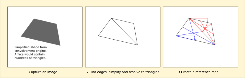
I've got a few ideas on replacing it. Another way is to reduce the image geometrically to a series of as large triangles as possible, abstract them into lists of angles and lengths and check them against a master list. Euclidian geometry concentrates on lines and areas in a theoretical space without metrics, a triangle is defined as the space enclosed by the crossing of three lines of infinite length, the relative angles of which are all that is important. Moving 1 or more of the lines around only changes the size of the triangle, and rotating it makes no difference. In comparing two triangles, Euclid defined them as congruent or not to each other. This means having identical internal angles, taking into account that the triangle may be scaled and mirrored too, but makes no account of where they are. Obviously I'm going to have to worry about the average colour of these triangles too to make this useful.
The first stage involves reducing the image mathematically.
At this point I have a representation of the image that I can store and compare, but it is unwieldy. The next stage involves abstracting the internal angles from all of the triangles to use them as an index into more complex information including scale and location in relation to the others.
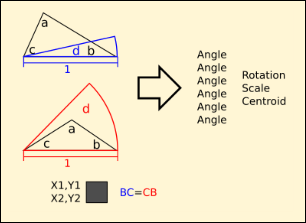
Lists of this information are stored to compare against, so that when another shape is matched the rotation and scale are unimportant.
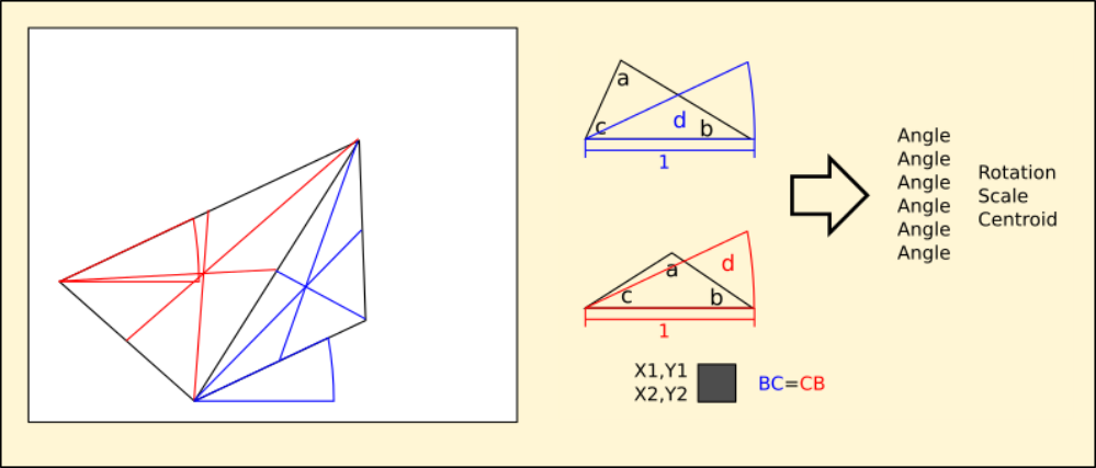
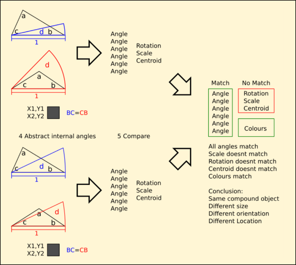
I've got a long way to go with this, other than some test code making a routine that returns a Euclidean abstract from a list of three coordinates and compares them for congruency I havent got very far.
Skeletronics
This is what I've been looking for digging through my backups. Its the host and client side code that drove AIME's servos. I used two Arduino Uno's so the code for them was identical.
I realised that to make smooth natural motion I'd have to do two things. One was provide a precise timer and synchronise every servo to it at the same time, and the other was define a paradigm to communicate with it. I implemented this as a language that talked to a 'driver' that translated the instruction hierarchy into timecode and uploaded it to the skeletronics controller, which synchronously timed the travel of each of the servos. This took the weight off the serial link between the behavioural processor and the controller, allowing controller to get on with dealing with the servos on its own.
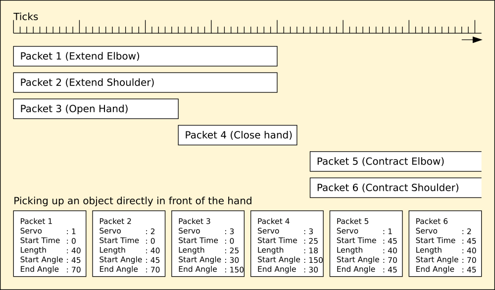
The whole point of this was to distribute the processing without placing too heavy a load on any one part of the system.
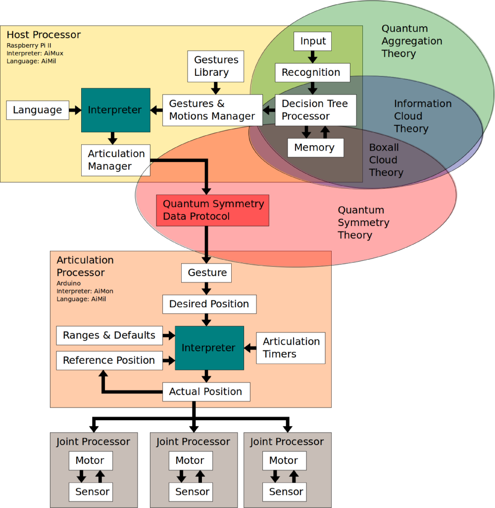
AIMux : User Interface Language Interpreter
Runs on the host processor, accepts instruction from the Decision Tree Processor via the Gestures Manager and processes it into AIMil. AIMil programs are stored and used to provide complex behaviours.
AIMil : User Interface Language
Syntax and dictionary of instructions to configure and articulate a complex system of vectors.
AIMon: User Interface Realtime Monitor
Sub-processing interpreter, accepts AIMil vectors into an asynchronous buffer and executes them synchronously to produce complex motion.
The AIMOS model is distributed in a hierarchy. Instead of using one large processor to do all of the work, the system processes events into basic actions in the Decision Tree Processor. This instructs the Gestures manager to locate and pass more complex ones to the interpreter.
For example the decision engine can output the verb 'move', which is translated into 'take a step' by the interpreter, which then programs the Articulation Processor with the appropriate complex timing and vector sets for the beginnings and ends of the individual motor movements. These are then synchronously sent to the Joint Processors to physically move the joint into the correct position and hold it there while the others comply with their instructions.
This is necessary, because to take a step requires intimate control of 24 motors each with its own sensor on microsecond timing, which cant be done through the bottleneck caused by the communications between the physical hardware. So the complex step instructions are stored the other side of the bottleneck, and simple referrals made to them through it, which is a lot faster.
AIMil
AIMil is the programming language used to control AIMos. It isnt like any programming language you've ever seen before because it isnt algebraic. It can use algebraic equations to calculate things but they exist only in the user space and internally AIMil uses a hybrid Euclidean geometry, although this is largely transparent to the user.
There are several important concepts to learn about AIMils geometry. It uses relational hierarchy to define coherent conceptions of the structure it is controlling. Because robots can have many basic forms like hexapods, quadrapods and bipeds and some dont move but have complex articulations to form a single limb AIMil defines them in a top-down hierarchy and passes control upwards to collect movements together under a single instruction.
You begin by naming each of the servos, and assigning a range of motion and a default position to them. This is so that when you issue a verb-noun-adjective instruction like
move left foot forward 100% (in English for now)
AIMil knows that although the servo can move from position 0 to position 255, it may be physically restricted to values between 50 and 200 by the chassis. Furthermore, the servo controlling the opposite limb joint may be upside down compared to the first, so to rotate it the same as the first its range is between 200 and 50. So that
move right foot forward 100%
sends 200 to the right servo, and 50 to the left foot so they both move forward even though the servos are physically reversed.
AIMil understands many adjectives, most of which are mutually inclusive of each other or are similes. For example
in and out, up and down, forward and back, toward and away, left and right, round and about
are all equal and valid to send to a single servo, however because limbs are collections of servos, they dont always make sense.
AIMil will quite happily do the opposite of what you wanted because a limb is upside down. Out becomes in and up becomes down, so to avoid confusion the servos are relational, and the adjectives refer to movement in respect of the parent – up and in instructions to an elbow joint always bring the hand towards the shoulder regardless which way the arm is oriented.
Because the architecture is so variable the notion of a body and limbs simply wont work in all cases and I decided against speciation to get around it. Defining several different ways of moving the different architectures was counter to the conception of AIMil being a single platform, so AIMos thinks of itself as an articulation – a network of parts with a familial hierarchy.
Simple familial hierarchy uses the concept of parent-child, where control simply runs downwards from the parent. Extended-familial hierarchy uses the concept of multiple parent-child-grandchild groupings so that control runs downwards from parent to child, and parents inherit properties from descendents as family units. This way one servo can be made to articulate the others around itself by defining them as its family. Anything a family member does can in turn affect the entire family by inheritance.
So AIMil defines servos as collections, and can also make collections of collections to form families that can be referred to as individual units that can control others. Because there is no notion of a body or chassis, a biped thinks of itself as four hinges with one common lever, which happens to be the torso. Each other end of each lever has another hinge on it, and the reference for the entire structure is taken from the one on the ground – all others rotate about this one including the actual chassis which is never directly related to the ground plane anyway.
A chassis-mounted arm is a series of levers and hinges, one end of which is always on the ground plane. The other end is common to a few hinges and levers making a hand with fingers which can be as complex as needed. This idea of geometry makes it possible to compute the positions of the individual servos in relation to the ground plane and thus the world – before this I struggled to reconcile anything external to the robot with its own point of origin, including even the ground plane which is fundamental; a biped really needs this information to balance, and an arm needs to locate its fingers with reference to its shoulder – which may or may not be directly connected to the ground plane.
In this way entire families of servos can be made to rely on the position of one individual, which is dynamic. Coordinates like 'in front of the robot' can be realised so that any other part of the whole can be made to touch that coordinate by articulating the others, which is another inherent ability I had to design into AIMos. Because these coordinates can only be computed and not calculated, its easier to learn them instead and store them so AIMil facilitates this once the physical robot is operational.
This brings with it the exciting possibility of damage recovery – if a biped damages a leg, currently it is considered non-operational and there is no mitigation other than repair.
Because AIMos' internal geometry refers to groupings of servos in contact with the ground plane it is possible for a biped to switch to quadruped motion if it loses a foot and cant stand, where a standard system just fails to walk. Thankfully the horrifying image of a mutilated Terminator dragging itself after Sarah Connor is way off, but the ability to adapt is one of the hallmarks of intelligence and has to be catered for as part of AIMos' remit.
The AiMil Language and Syntax
AIMil programs are enclosed in curly braces like C++ to define its sections, however unlike C++ all the subsections are contained within a master block:
aimil {
    vars ...
    servos ...
    poses {
        track movement...
        recognise objects...
        move servos...
    }
    engage {
    call pose routines...
    quit on test
    }
}
The master block contains variables as needed, servo definitions and at least one pose routine.
These are called repeatedly by the engage block unless the quit condition is satisfied, which can be omitted completely to just run forever. This is the bare minimum needed to create a an AIMil program.
AIMil Instructions
The following is a list of the instructions AIMil understands.
aimil { }

The main AIMil program block. This must be present and contain valid
code to compile.
        var <variable> { }   var <variable> { <subvariable> }

eg:	var testing { test1 test2 }		var testing { }

	testing.test1 = value			testing = value
	testing.test2 = another value

Create a variable to store a value, or optionally a list of named
values as a named collection.
        servo <name> { id pin min max home plane }


eg:     servo x_servo { id 1 pin 2 min 0 max 255 home 128 roll }

        servo y_servo { id 2 pin 5 min 200 max 50 home 128 pitch }

Define a servo description.

<name>  A single string with no spaces or special characters except
        underscore as a separator.

Id      A unique number between 1 and 12 to identify the servo
        numerically.

Pin     The physical Arduino/Atmel pin assignment the servo name and
        id map to. Pin starts at 2 because Atmel boards use pins 0 and
        1 for communications.

Min     The end of the range that 'down' points to.
        Can be between 0 and 255.

Max     The end of the range that 'up' points to.
        Can be between 0 and 255.

Home    Default resting position for the servo.
        Usually halfway between min and max but can be any value from
        min to max.

Plane   Pitch, yaw or roll - the way this servo is oriented with every
        other servo homed.
set <name> { <value> or <computation> }
eg: set testing.test1 { 1 } set test { x_servo.id }
set test { y_servo.id - 1 } set testing { true }
Set a variable to a value directly, or indirectly through another
variable or parameter or through a computation.
        pose  { }

Define a Pose block. This is a subroutine that can be called by name
from the Engage block and contains code to interact programmatically
with the servos in response to sensor information.
movement { <variable> } -> <variable>.horz
<variable>.vert
Get the latest tracking information into the named variable.
This will overwrite the original contents with the Cartesian
coordinates of movement in the current video frame. It doesnt matter
if the compound variables inside it arent named correctly or even exist
but the variable must.
        recognise { <variable>  } ->  <variable>.object
                                      <variable>.horz
                                      <variable>.vert

Get the latest recognition information into the named variable. This
will overwrite the original contents with a recognised object and its
Cartesian coordinates from the current video frame, or 'none' if there
isnt anything. Which object can be determined by comparing it with the
special memory variable. The named variable must already exist.
compound <family> { <parent> <child> }
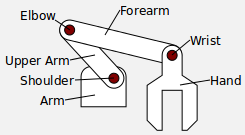
eg: compound forearm { wrist hand }
compound upperarm { elbow forearm }
compound arm { shoulder upperarm }
Collects groups of servos together in a hierarchy. Careful use of this
command can build tree networks which logically describe a compound
appendage with many subparts.
The example shows how to build a simple arm with nouns to describe
each lever and hinge and how it is arranged with respect to the
others. Wrist, elbow and shoulder are the actual servos.![]()
        test as  {  }

eg:     test as done { counter > }    test as same { 0.4 ~~ 1.1 }
        test as valid { found = true }

Compare two values, results or logical operators and set the named
variable to true or false as a result of the operation. The original
contents are overwritten and the variable must already exist.

        Comparators include == equal            != unequal
                            >= greater or equal <= lesser or equal
                            ~~ approximately equal

The approximal comparator (~~) is used to check if two values are less
than 1 unit different in size. This is not an integer operation. In
the example shown, 0.4 minus 1.1 is -0.7 : less than absolute 1 so the
values are considered approximately equal and it returns true, where
an equals comparator returns false when comparing integers 0.4 and 1.1
        wait { ticks }

Pause for the specified number of ticks before continuing. Ticks are
synchronised to the master clock in the Articulations Processor.
        engage { }

The master loop. This is repeated until the quit condition is
satisfied by setting quit { true }.
This can be used as above to run the engage block just once or omitted
completely to keep executing the engage block forever.
quit { <condition> }
eg: quit { true } quit { done }
Sets the boolean value of quit to the content of the specified
variable or condition.
The master loop will exit at the end of the current pass unless this
flag is false.
        <pose routine>

eg:     main_block    step_left   dance

Routines created in a Pose block are called by naming them. All
variables are global and are shared between the Engage block and all
Pose blocks.
        <name> { <position> at <tick> by <steps> }

eg:     left_knee { 0 at 1 by 1 } # to position 'min' in 1 step
        left_knee { left_knee.home at 6000 by 255 }


        <name> { <verb> by <percentage> <adjective> }

eg:     left_arm { out by 100 fast } left_arm { up by 100 fast }


Controls servos on a timed schedule using the first syntax. Name is
either a servo or compound, so that you can program an entire
synchronous motion involving several servos directly. Using compounds
is slightly more complex because you are addressing more than one
servo with one command, and servos inherit motion they cant physically
address; an arm's shoulder comprises two servos for 3D motion, one can
move up and down, the other in and out. When addressed as family
'shoulder' the adjectives of both servos are combined, because
'shoulder' inherits both abilities.

The second syntax is used for direct asynchronous control of servos in
the same manner, however there is no way of synchronising them to the
clock. This is intended for gestural and spot motion and can be used
in parallel with synchronous motion eg to wave at something while
walking.
Example AIMil program showing how most of the commands work and how to use them. This setup would control a biped with a chassis-mounted camera to make it track movement:
aimil {

    var track { horizontal vertical }
    var recog { object x y }
    var hand { }
    var done { }

    servo left_ankle { id 1 pin 2 min 90 max 50 home 74 roll }
    servo right_ankle { id 2 pin 3 min 90 max 130 home 104 roll }
    servo left_knee { id 3 pin 4 min 70 max 170 home 112 pitch }
    servo right_knee { id 4 pin 5 min 100 max 28 home 58 pitch }
    servo left_hip { id 5 pin 6 min 170 max 50 home 116 pitch }
    servo right_hip { id 6 pin 7 min 10 max 170 home 58 pitch }

    set done { false }

    pose watcher {
        movement { track }
        recognise { recog }
        left_hip { left_hip.home + track.horizontal / 2 at 1 in 3000 }
        right_hip { right_hip.home + track.horizontal / 2 at 1 in 3000 }
        left_ankle { left_ankle.home - track.horizontal / 2 at 1 in 3000 }
        right_ankle { right_ankle.home - track.horizontal / 2 at 1 in 3000 }

    }

    engage {
        watcher
        wait { 3000 }
        set hand { memory { 1 } }
        test as done { recog.object == hand }
        quit { done }
    }
}
![]()
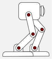
This program is surprisingly capable despite its brevity. The built in Movement module is used to get the centre position of an area of movement in Cartesian format, expressed as percentages of width and height of the video frame from the centre of frame. This avoids problems with the different types and resolution of camera AIMos can use; all I need to do is divide the result by 2 and add it to the home position because it is already between -100% and +100%.
Thus if the movement is at the left edge of the frame, the Movement module returns -100. The left hip and ankle servos are lined up the same, so both their min positions point backward. This is mirrored on the other leg, where the min positions point forward. Both home positions are in the centre of the range, at 50. So by adding half the horizontal percentage of movement to the hip position, the left hip moves back and the right hip moves forward by the same amount. This pushes the left heel down and forward, and the right toe down and backward so the ankle is then flexed by the same amount to keep the feet flat while moving backwards and forwards in relation to each other. Because both feet are flat on the floor, the chassis swivels around them.
To accomplish this, the Recognise module is used to get the latest recognised object in the frame, if any. This is stored in the variable 'hand', and is compared to Memory module slot 1, which contains a hand in a halt gesture. If they match, the program exits and the robot returns to interpretive command mode.
All the time the program runs, the camera detects motion and recognises objects. The coordinates of the motion are passed to the controller which determines how much to move the hip and ankle in each leg. It does this until you tell it to halt with a hand gesture.