Close
0%
0%

Power Monitoring for your Mobile Home

In this project I built an energy monitor for a RV / Mobile Home site hook-up. It has a smartphone Bluetooth app and data logging.

Similar projects worth following
228 views
0 followers
Projects come in various motivations: some for learning a thing, some for teaching a thing, and some simply because you want the thing. This particular project falls into the latter category. With the recent surge in energy prices, many Mobile Home and RV sites have introduced additional charges based on electricity usage. My father-in-law approached me, seeking a solution to monitor his electricity expenses accurately.

I aimed to create a user-friendly device, easily resettable after site moves, and equipped with Bluetooth connectivity for convenient monitoring via a mobile phone. Additionally, I incorporated data logging to track energy consumption over time. Although I don't own an RV or Mobile Home myself, I recognize the potential utility of this project, even in my professional capacity, for monitoring energy usage in industrial settings.

This project involves mains voltages, and where I live the mains voltage is 230V AC. This can and will kill you. I have taken many precautions to make this project as safe as I possibly can. Please do not attempt this project unless you are suitably qualified and experienced to work with mains power supplies.

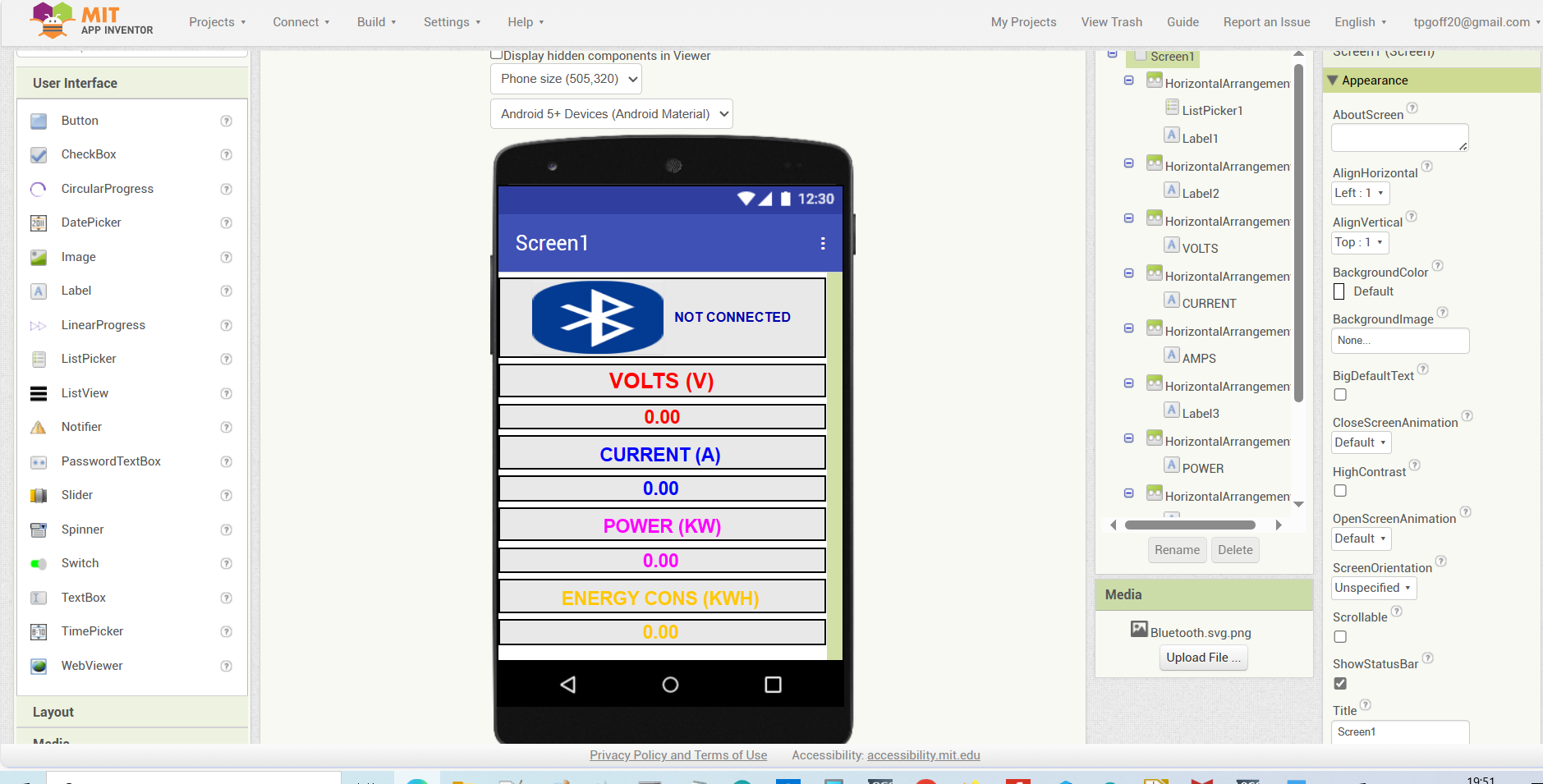
In summary the project comprises of an ESP32 that takes data from an PZEM-004T module. The PZEM-004T is an electrical energy monitor designed to measure voltage, current, power, energy, and frequency in AC circuits which provides real-time data on energy consumption. This data is displayed on an OLED screen, saved on an SD card and sent via Bluetooth to smartphone app.

Here's a short video demonstrating what the power does and how it connects to a smart phone via Bluetooth classic.

RV_PowerMeter_PZEM-004T_30.03.24.ino

Arduino Code for ESP32

ino - 7.06 kB - 03/30/2024 at 17:44

Download

x-zip-compressed - 57.08 kB - 03/30/2024 at 17:36

Download

  • 1 × ESP-32S Micro Controller Development Board DigiKey Part Number: 1965-ESP32-DEVKITC-DA-ND - ESP-WROOM-32 - 2.4 GHz Dual Core WLAN WiFi + Bluetooth
  • 1 × PZEM-004T & Curent Transformer Current, Voltage, Power, Energy, and Power Factor Module AC 80-260V 100A
  • 1 × Micro SD Module DigiKey Part Number: 1528-1462-ND
  • 1 × Micro SD Card - 16GB DigiKey Part Number: 3247-USDCOEM-16GB-ND
  • 1 × OLED Display 1.3 Inch, I2C

View all 27 components

  • 1
    PCB Design

    The PCB design is really just a motherboard to link the various breakout boards I used to the ESP-32 wroom dev board I used. 

    The PCB is powered by by the electrical hook-up and comes on everytime the hook-up is connected and powered up. For this I simply used a small 230V - 9V step-down transformer, a bridge rectifier and and LM7805 linear regulator with a larger smoothing capacitor and couple of smaller capacitors working as low pass filters. This is pretty much a simple "classic" power supply design, not sophisticated at all but it works.

    The backbone of this project is the PZEM-004T module, known for simplifying energy monitoring tasks. While measuring RMS Voltage and Current poses relatively fewer challenges, accurately determining power consumption necessitates Power Factor measurement. The Power Factor varies based on the load's composition, whether primarily inductive, capacitive, or resistive. A purely resistive load maintains a power factor of 1, but the inclusion of capacitors or inductors causes voltage and current to shift out of phase, resulting in a power factor less than 1. A consumer is charged for "Real Power" which is calculated as below:

    Real Power (P) = Volts (V) X Current (Amps) x PF

    Despite the complexity of Power Factor measurement, it can be achieved with a microcontroller using zero-cross detectors on current and voltage, assessing the time difference. Opting to streamline my project, I employed the PZEM-004T module, efficiently handling these complexities.

    The PZEM-004T module relies on a specialized integrated circuit (IC), alongside a current transformer and shunt resistor, to precisely gauge current flow and voltage levels in the connected circuit. Operating within the standard AC voltage range of 80-260V and capable of measuring currents up to 100A, it accommodates a wide array of electrical systems, making it a versatile choice for various applications.

    Because the PCB has mains power coming into it I have made sure there are certain safety measures implemented. These include ensuring there is an air gap slotted into the PCB between the live and neutral incoming supply terminals. I have also removed the ground plane away from the zone on the PCB that has the mains supply. I am by no means a professional PCB designer so I urge you to seek professional advice before building a PCB that involves high voltages.

    I've included a Zip file in the files section of this write-up with all the required files in it if you would like to have a PCB made up.

  • 2
    The Code

    As I mentioned in the project description, the point of this project was because I wanted the finished device to use. I wasn't planning to to anything technically ambitious so I just put some code together using the Arduino IDE and shamelessly took advantage of the library's available for the individual breakout boards and modules I used. 

    The code is for an ESP32-based energy monitor with display and Bluetooth Classic capabilities. Here's a break down of how the code functions.

    Libraries and Definitions - The code begins with including necessary libraries for various functionalities such as communicating with the PZEM004Tv30 energy monitor, handling real-time clock (RTC), Bluetooth communication, OLED display, and SD card. Additionally, it defines some constants like the reset pin and screen dimensions.

    Global Variables - The following Global Variables are then set

    • SerialBT: BluetoothSerial object for Bluetooth communication. display: Adafruit_SSD1306 object for OLED display. 
    • chipSelect: Pin for SD card chip select. 
    • myFile: File object for writing data to the SD card. 
    • rtc: RTC_DS1307 object for real-time clock functionalities. 
    • pzem: PZEM004Tv30 object for interacting with the energy monitor.

    Setup () Function
    setup(): This function is executed once at the start of the program. It initializes serial communication, Bluetooth, display, RTC, SD card, and attaches an interrupt to the reset pin.

    Interrupt Function
    There's an interrupt function resetEnergy() attached to the reset pin (pin 33). It resets energy values in the PZEM004Tv30 sensor when triggered.

    Main Loop

    The main loop starts by getting voltage, current, power, energy, frequency, and power factor from the energy monitor. Getting the data from the PZEM-004T is very easy using the following code.

      // Read the data from the sensor
      float voltage = pzem.voltage();
      float current = pzem.current();
      float power = pzem.power();
      float energy = pzem.energy();
      float frequency = pzem.frequency();
      float pf = pzem.pf();

     Next we check  whether there is valid data from the PZEM-004T using the inan()  (Is Not A Number) function. If the data is not valid a message is displayed on the Serial Monitor, this is really for de-bugging.

    Provided the data is valid it calls the the following three functions:

    • logData() - logs data to the SD card with a timestamp taken from the real time clock.
    • displayData() -  Displays voltage, current, power, and energy on the OLED screen. 
      • BTData() -  Sends voltage, current, power, and energy over Bluetooth.

    The voltage, current, power and energy data from the PZEM-004T is passed to the above three functions.

    When the program returns to the main loop it prints the data to the serial console, the data also includes the Power Factor which I have not included in the OLED display function and SD card logging function as I don't believe it is required.

    To summarise, the code initializes various components, continuously reads energy data, logs it to an SD card, displays it on an OLED screen, and sends it over Bluetooth classic. 

    I know the code needs work but a copy of the code is available in the files section of this write-up.

  • 3
    Cell Phone App

    I built a cell phone app to complement this project as I feel that we are entering an age when everyone expects their electronics to seamlessly connect to their phone. A cell phone app offers convenient access to real-time electricity data with a user-friendly interface. The ease of access should empower users to manage energy efficiently.

    To continue with the pragmatic "just get it built" philosophy of this project I used a tool called MIT App Inventor to build the mobile App. MIT App Inventor is a user-friendly, visual programming environment that enables individuals to create mobile applications for Android devices with little or no app coding experience. It offers a drag-and-drop interface for assembling app components, simplifying the app development process. Here's a simplified method describing the steps I used for building the app.

    1. Create an Account: Visit MIT App Inventor website https://appinventor.mit.edu/ and sign in or create a new account.
    2. Start a New Project: Click on "Start new project," give your project a name, and choose a blank template.
    3. Design the User Interface (UI):
      • Drag and drop components from the palette onto the designer canvas (phone screen).
      • Add buttons, text boxes, labels, and other UI elements as needed.
    4. Set Properties: Customize the appearance and behaviour of UI components by adjusting their properties in the Component Tree or Properties pane. This could be the setting and sizing of text fonts.
    5. Add Functionality with Blocks:
      • Click on the "Blocks" button to switch to the Blocks Editor.
      • Use event handlers like "When Button Clicked" to add functionality.
      • Drag and connect blocks to define the behaviour of the app, such as "if / then / else statements". For example the esp32 in this project broadcasts the data over bluetooth. The data is sent as one long string of characters. In the Arduino code have put the separator "|" between the values of voltage, current, power and energy consumed. The bluetooth app receives the string of data and then converts it into a list by iterating through the list and identifying each item on the list by splitting the long string of data every time it comes across a "|".
    6. Install the App on you phone:
      • Click on the "Build" button to generate the APK file and install it on your device.
      • Download the app
      • Transfer the app to your phone, I used the SD card.
      • Open up the folder on your phone where the App was saved, click on the app and install it.

    Once you have installed the app on your phone you will need to click on the bluetooth icon and a list of available devices will show up. Click on the ESP32 device and you should be good to go and your real-time data will appear.

    I have included some images of design and blocks of my App together with a short video showing the design and installation process.

View all 6 instructions

Enjoy this project?

Share

Discussions

Similar Projects

Does this project spark your interest?

Become a member to follow this project and never miss any updates