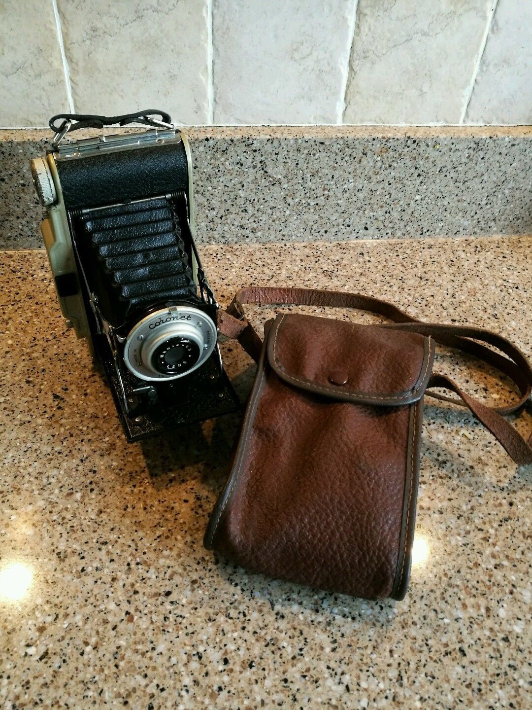
Every couple of years my local rugby club goes on tour. A few years ago the trip was to Enschede in the Netherlands where the impossible project is based. This inspired me to buy a vintage polaroid land camera on eBay along with a couple of packs of film to take along and get some physical photos of our travels.
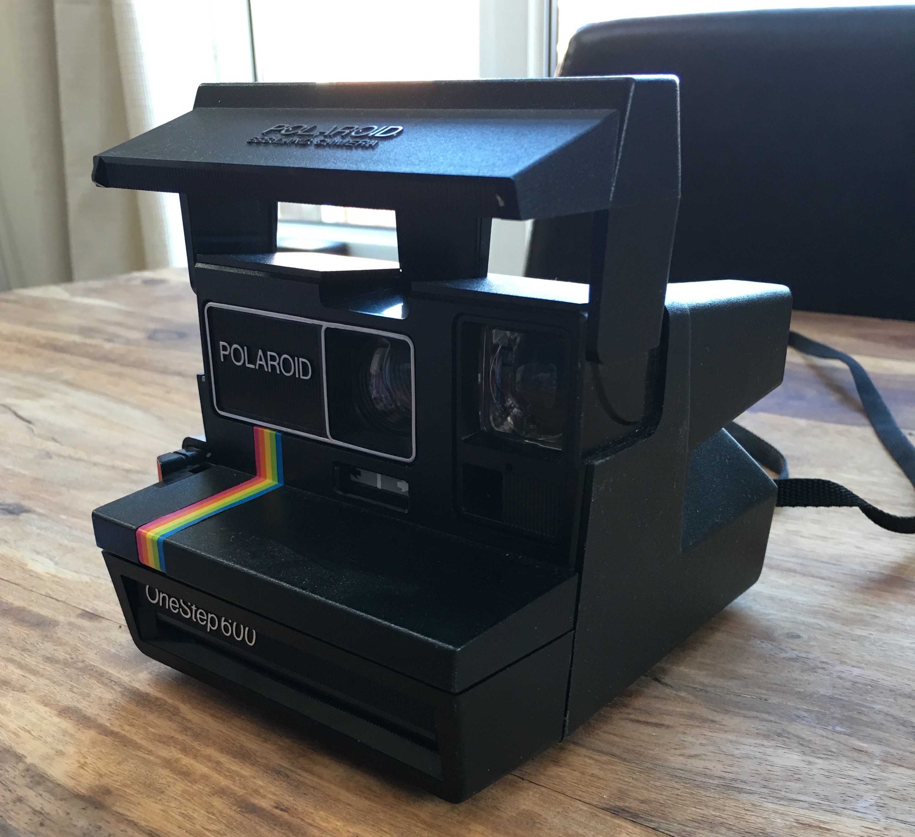
This worked a treat and I got some great photos, however I wanted to do something more adventurous and 'hacked' for the next instalment.
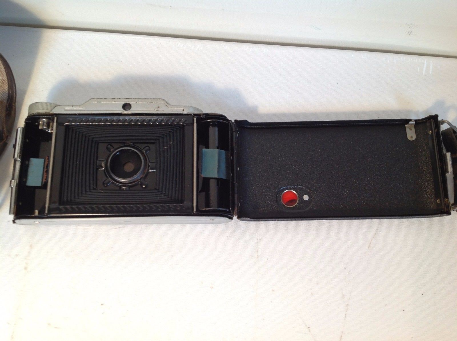
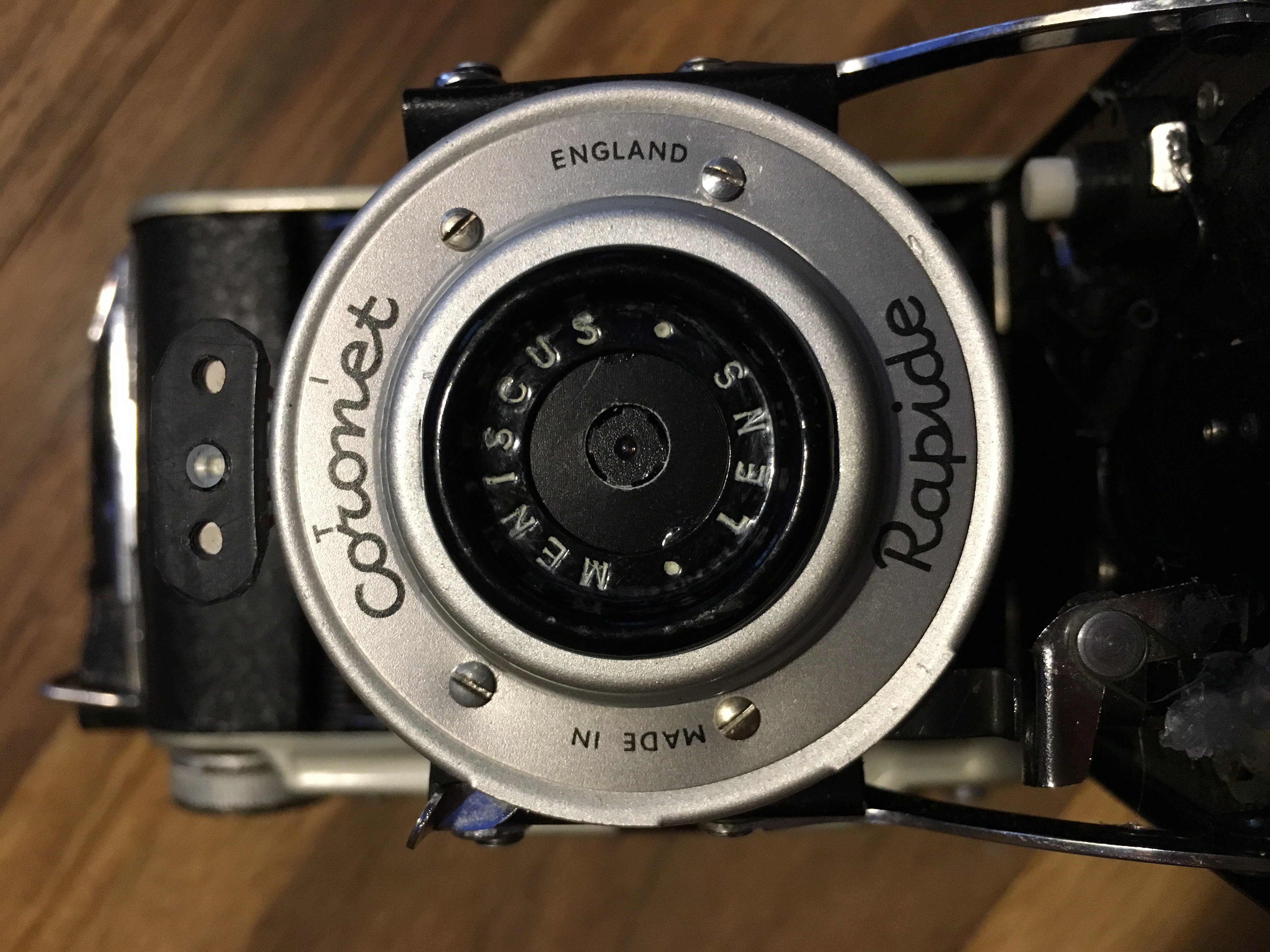
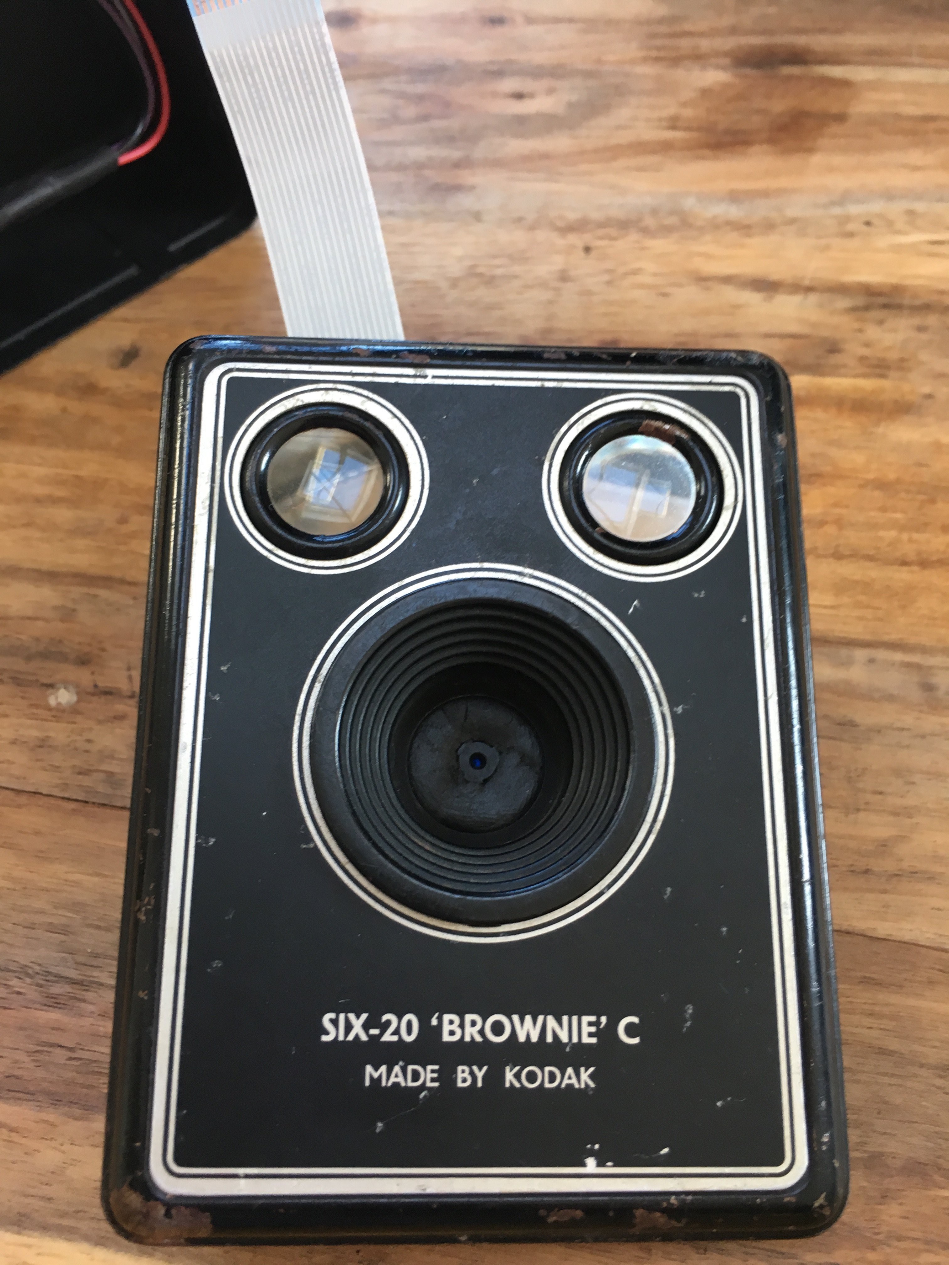
Enter the 'Box Brownie' - Camera 2.0 (stock photo)
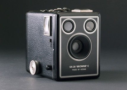
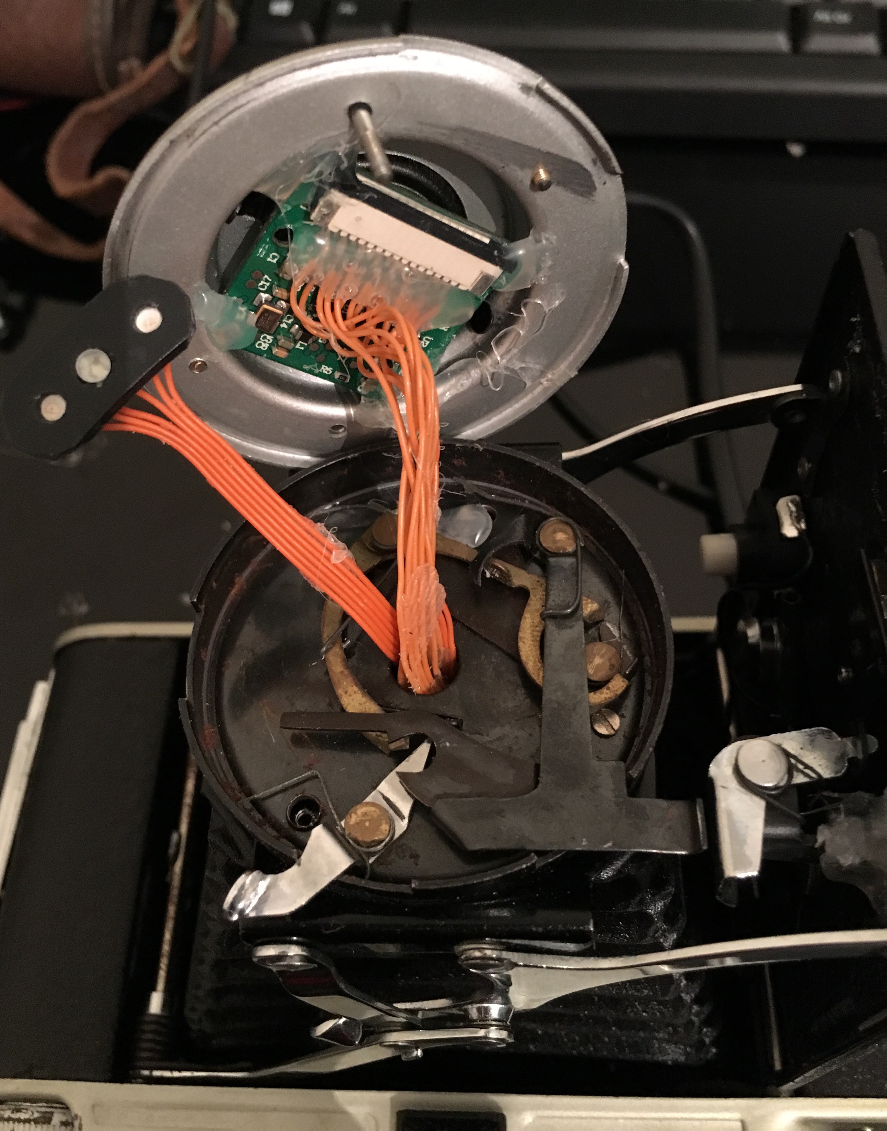
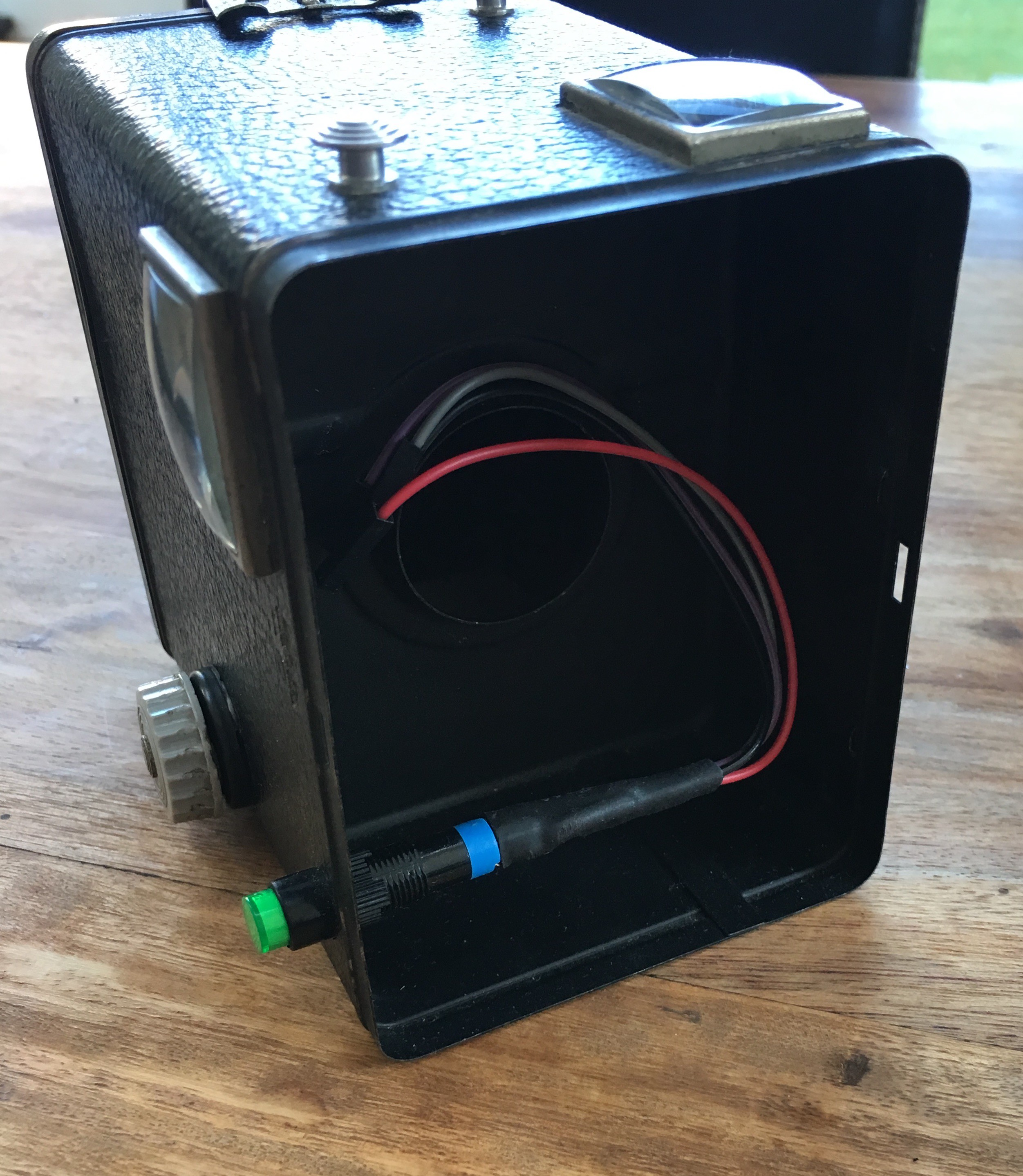
This was to be the first camera fitted with digital insides. Described in the project log.
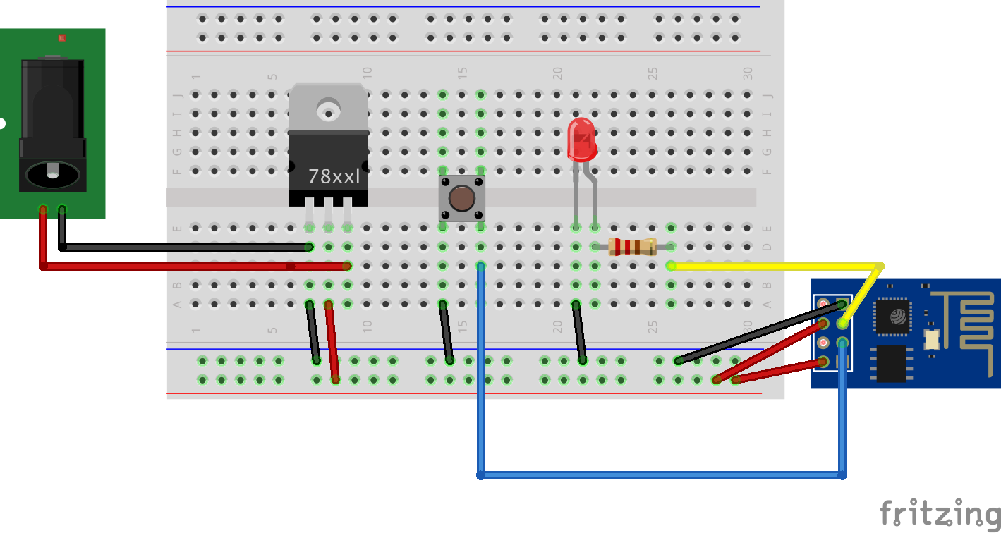
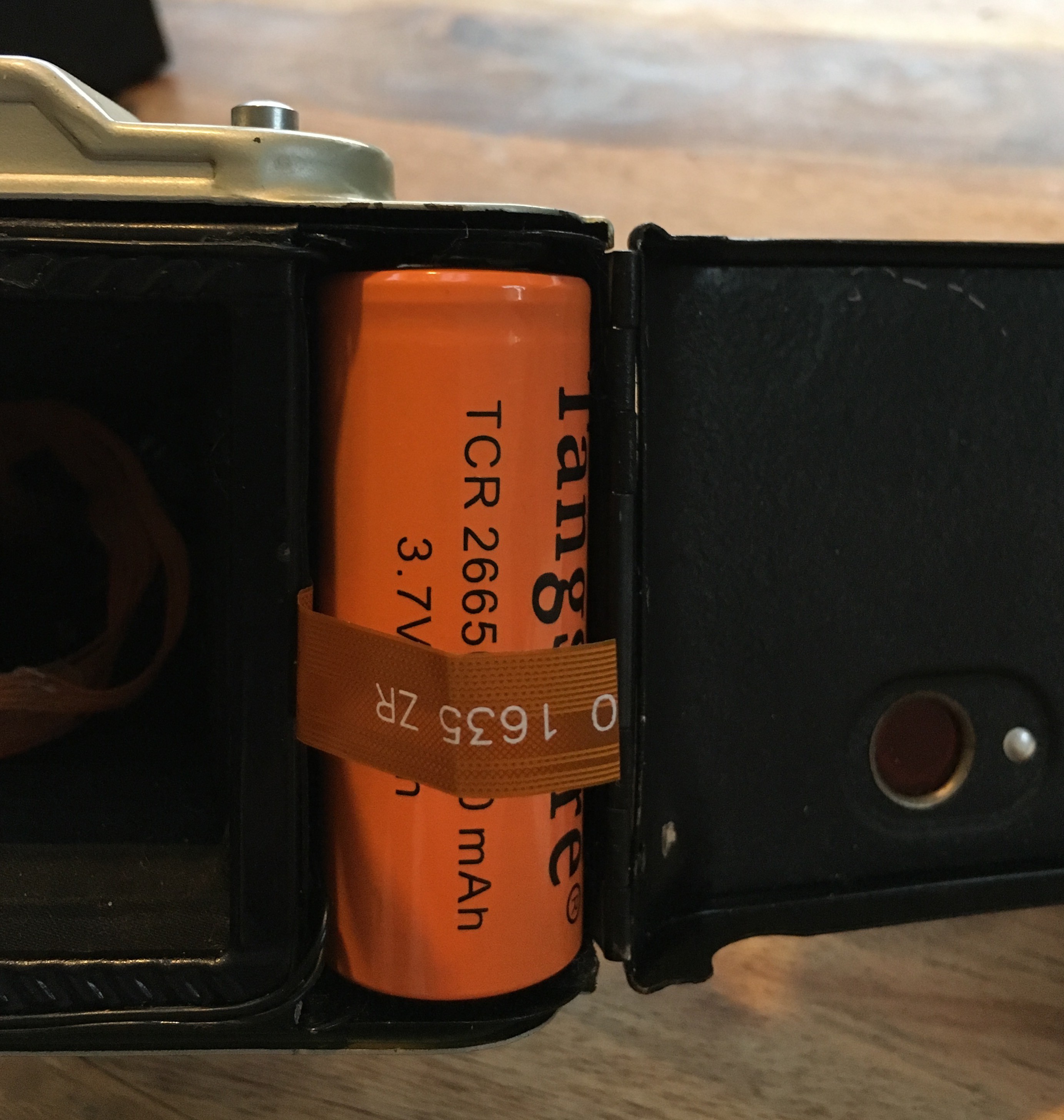
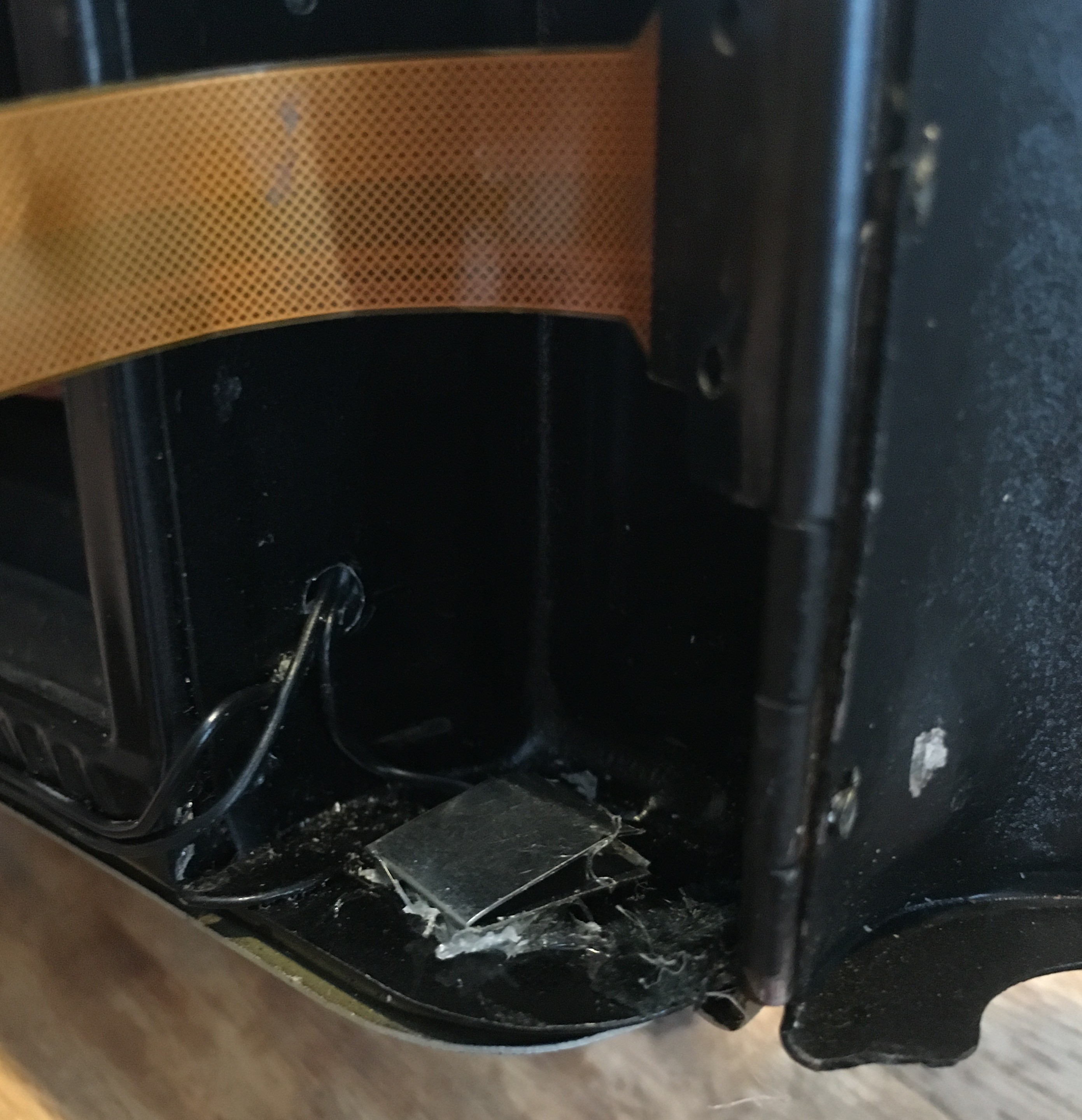
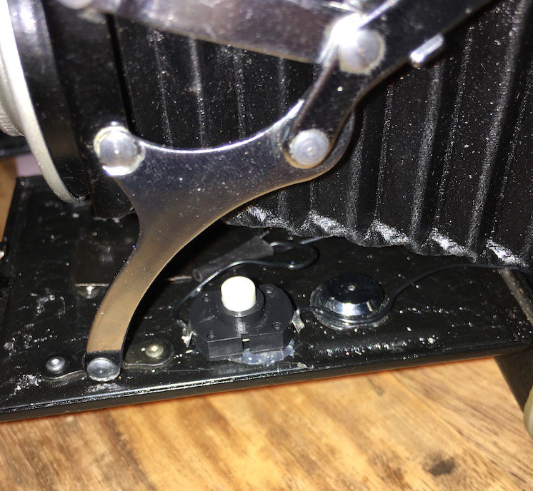
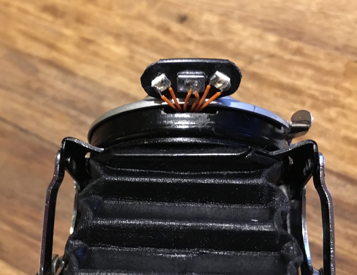
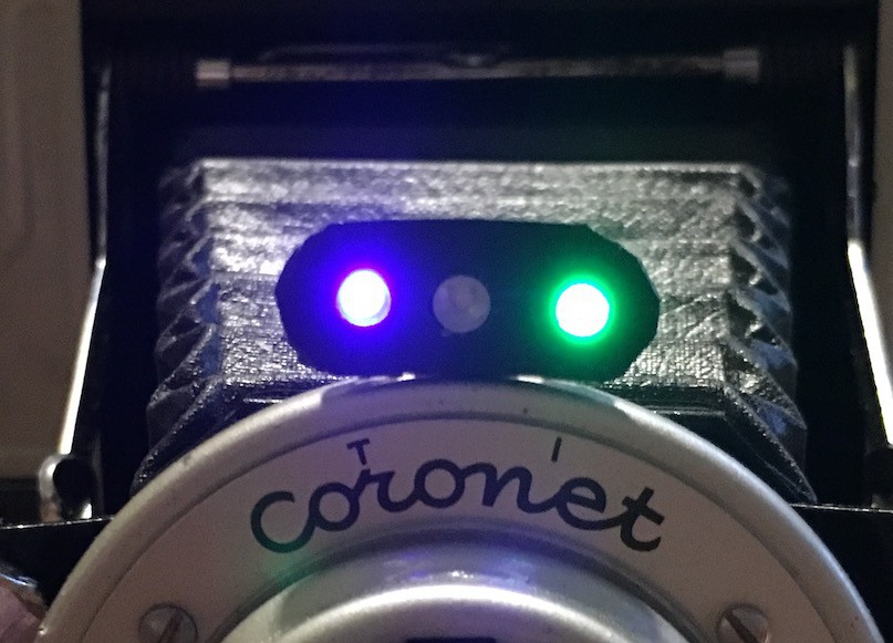 The cutting/shaping of the black plastic isn't as neat as I'd like, but it does the job. The blue LED is lit when the Pi has power (it runs of the constant 3.3v from the GPIO connector) and the green LED lights when the camera is ready (it is connected to a GPIO pin that is controlled in the python...
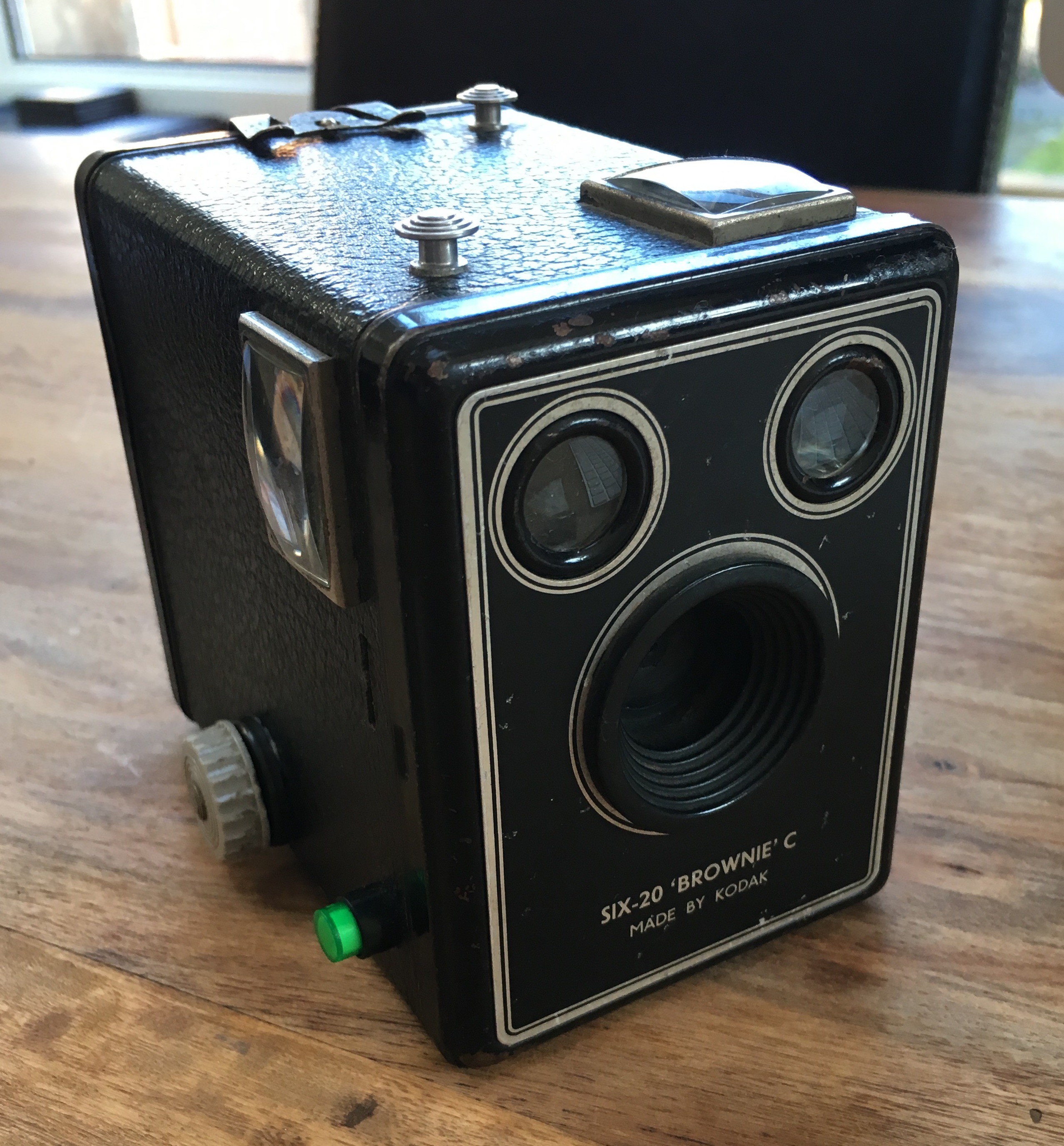


 Audrey Robinel
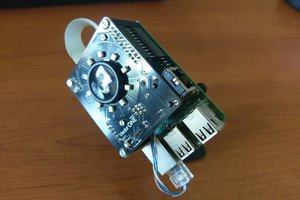
 Robert Gowans
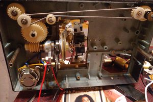
 The_Mekon
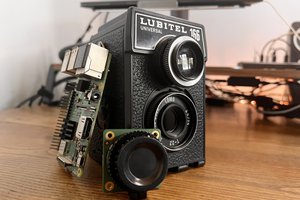
 Gradivis
Hi there, your hacks are cool !
Seems somewhat similar to Passamonti Francesco's one:
https://hackaday.io/project/12486-film-camera-to-digital-camera
It would be great to establish some collaboration to let both evolve.
Hope that inspires !