Got the hall effect current meter PCB back from OSHpark, tested it out on my AC mains, and it worked!
So, I wanted to be able to measure the current in the Camry and other parts cheaply, and without contact. TI makes a nice bipolar hall sensor with high bandwidth, TI DRV5053. So, I created a simple PCB and got it made at OSHpark.
I assembled it and snapped it into a 3D printed holder, and clipped it next to my L1 mains line.
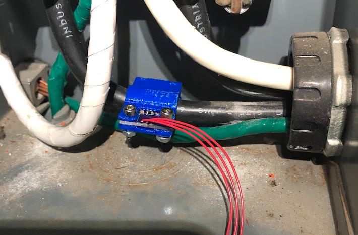
The hall effect sensor is held approximately 8 mm away from the center of the conductor. At that distance, 1 Amp in the wire will give rise to 2.61x10⁻⁵ T at the sensor. For an online magnetic field calculator, see Hyperphysics. The ADC was a raspberry pi pico, with a reading of 0-65536 from 0 to 3.3V. Luckily, the TI sensor will output 0 to 2 V, so within the range of 0 to 3.3 V. For no magnetic field, you get 1 V out of the sensor, for 2 V that means a magnetic field of 0.011 T, and for 0 V, that means a field of -0.011 T (sensor is bipolar). At 0.011 T, that would be a current ~426 Amps. Pretty good for a $2 sensor. :)
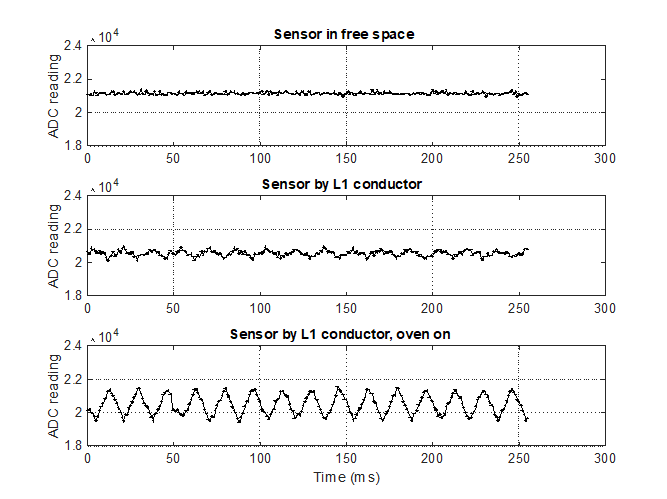
Here is a plot of the readings. The top figure shows the sensor reading for the sensor in free space. The raw ADC reading is about 21000 (i.e., 1V in). The next reading is the sensor by my mains L1 conductor, with the small background load of the house. The bottom graph is when I turned my oven on.
Converting raw ADC values back to Amps in the cable gives:
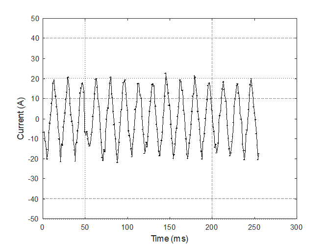
So, roughly 40 Amps peak to peak, or 20 Amps peak, or 14 Amps RMS. 14*240 = 3360 W, so pretty reasonable for the oven.
Discussions
Become a Hackaday.io Member
Create an account to leave a comment. Already have an account? Log In.