 Mikkel Nepper-Christensen
The LCD slide will consist of 4 parts:
- A frame that will hold LCD display
- 3310 LCD display
- Elastomer connector bracket
- PCB
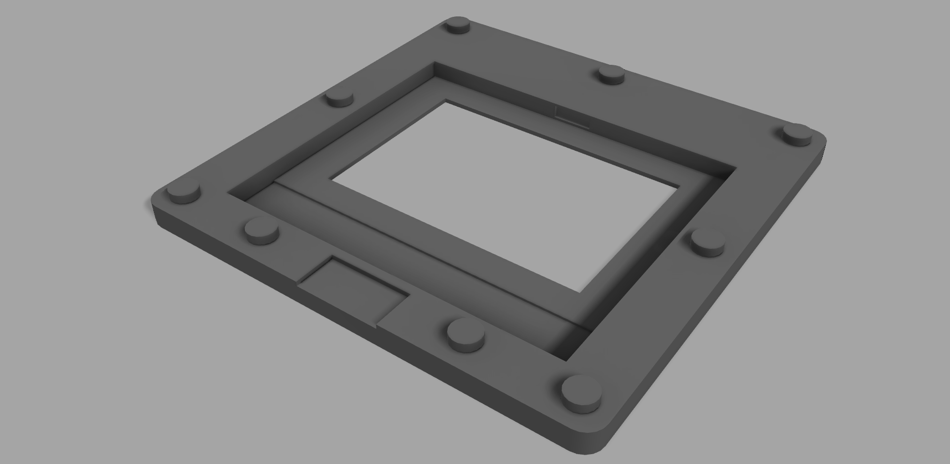
The frame will hold the LCD display and limit the light passing through the slide to the 84x48 pixel area of the LCD. The tabs will be used to keep the PCB in place while the small slot in the bottom is for the FFC (Flexible Flat Cable) that will be soldered to the bottom of PCB.
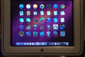
The bare LCD Display, when stripped down, is basically is two sheets of glass layered on top of each other with a pad-like conductive area in the lower part of the bottom glass sheet. You can see an image of this specific display here. I removed the white backlight diffuser sheet, as I don't use backlight and the light has to pass through the LCD.
The tricky part is now to connect a cable to the 9 pads on the display. This variant of the display uses a elastomer connector to connect the display to the PCB, so I will do the same and solder a FFC cable to the PCB. I have no idea how this will turn out, but I hopefully if I print a small bracket with a slot to hold the elastomer connector and if I manage to cut the connector to a hight of 1.15mm this may work.
The two extra holes in the bracket are clearings to make room for two small SMD capacitors on LCD. 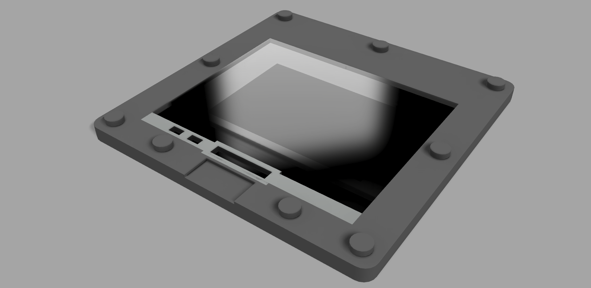
Slide with LCD and elastomer connector bracket (white part).
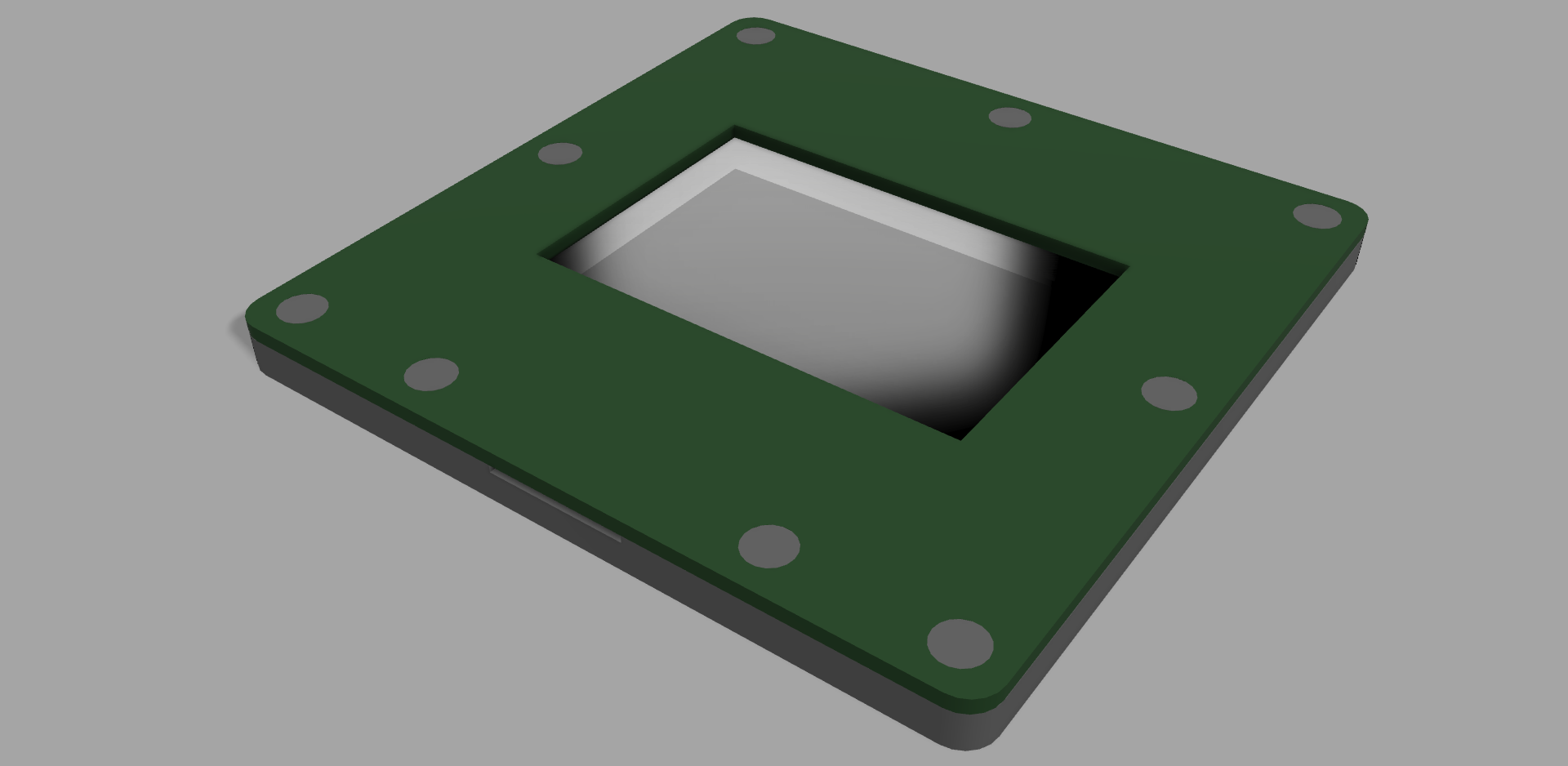
Finally on top of everything a 1mm PCB that will have similar pads for the elastomer connector and pads to solder the FFC cable (not illustrated).

 Chris Tully
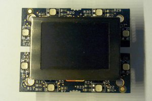
 sidsingh
 Martin Hub
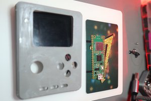
 Saul
Saul
Sure, it would have been interesting to do that. But space is very limited as the slide gate on this particular projector doesn't allow slides thicker than 4mm to be inserted. So my plan is to have only the display in the frame and connect to the display with an 8 pin FFC cable. As you mention powering a microcontroller in the frame would be a problem anyway.
I will have to add more details to the project.