mircemk
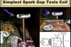
A Solid State Tesla Coil (SSTC) is a type of Tesla coil that uses solid-state components such as transistors, diodes, and capacitors to generate high-voltage, high-frequency alternating current electricity. This type has several advantages over traditional Tesla coils, which typically use spark gap switches. SSTCs have higher efficiency, the possibility of long-term work, as well as compact dimensions. In fact, compactness and small dimensions are the main characteristics of the Tesla coil, which the construction and operation are described in this project.
But despite the small size, the performance is surprisingly good. Another positive feature is its extreme simplicity, so even less experienced self-builders can make it. However, I would like to emphasize that generally making and adjusting any tesla coil, even though it looks simple, requires adequate knowledge and experience, especially at SSTC, where every small mistake and failed start means burnt components, which are not cheap.
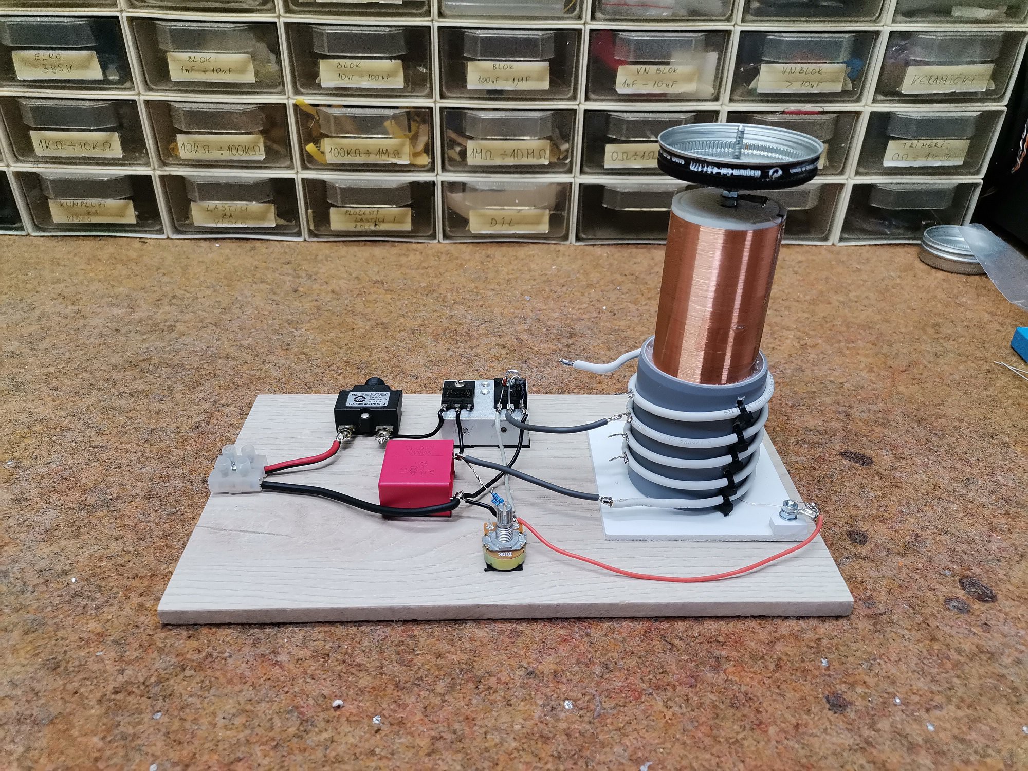
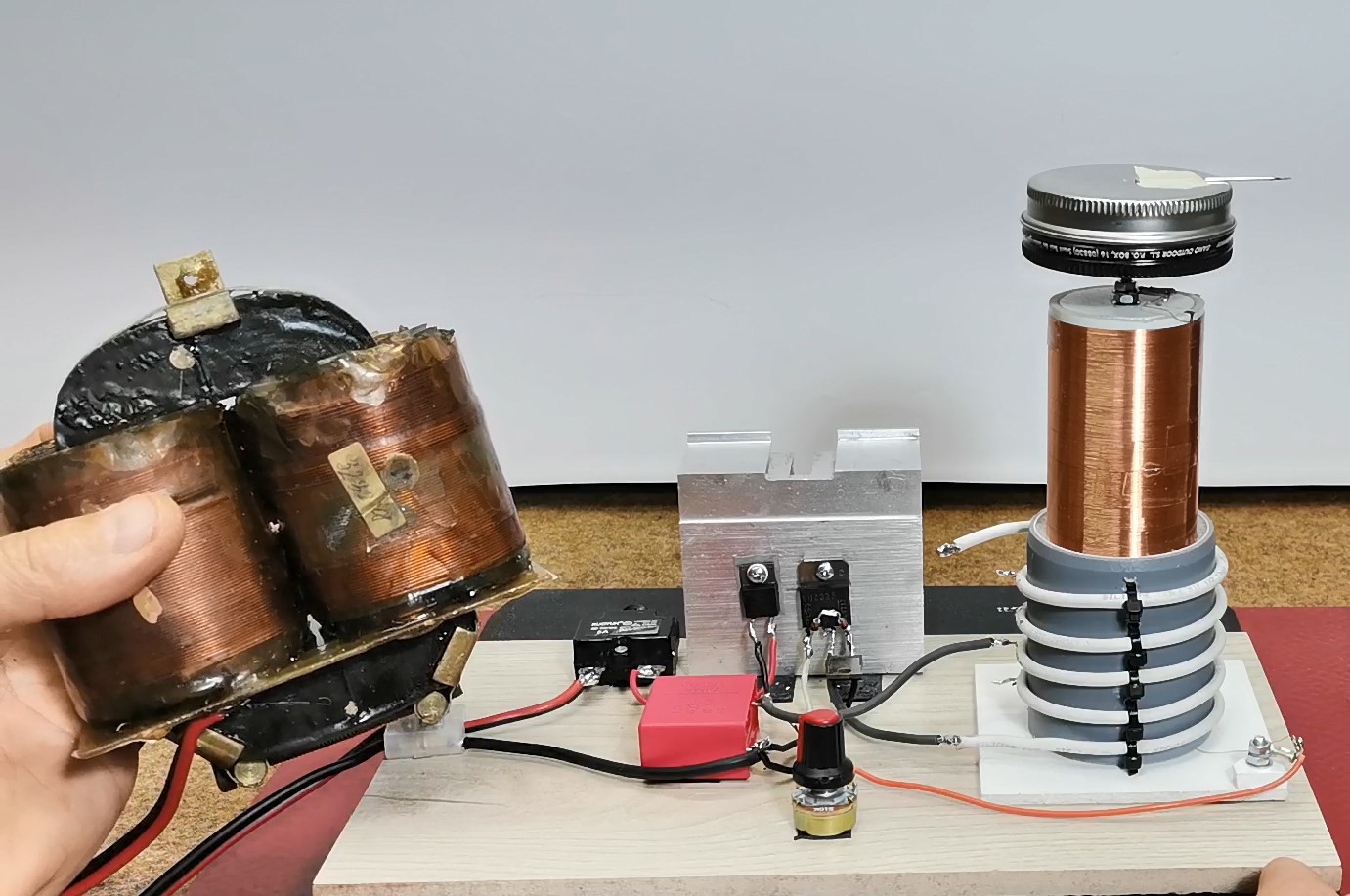
Тhe device consists of only a few components
- Primary coil
- Secondary coil
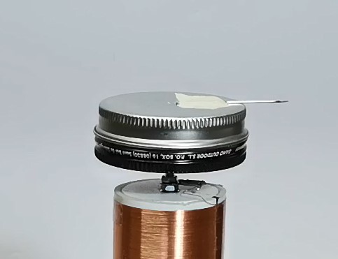
- Topload specifically in the form of a cylinder
- Powerful Mosfet (currently I use BUZ325, but in the first prototype I used IRfP460 with the same results)
- Heatsink for the mosfet
- diode 5 amp, for example U1540
- Fast diode for Mosfet protection also U1540
- 1microfarad/250V MKP capacitor
- Potentiometer and Resistor
- Two Zener diodes for 12V
- Fuse 5A
- And source of alternating voltage - Transformer 50V /3A or more
This project is sponsored byPCBWay. They has all the services you need to create your project at the best price, whether is a scool project, or complex professional project. OnPCBWay you can share your experiences, or get inspiration for your next project. They also provide completed Surface mount SMT PCB assemblY service at a best price, and ISO9001 quality control. Visit www.pcbway.com for more services

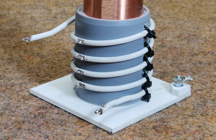
The primary coil contains 5 windings of 2.5mm copper wire on a plastic body with a diameter of 5cm, and it is desirable to make a lead on each winding to make it easier to adjust the device.
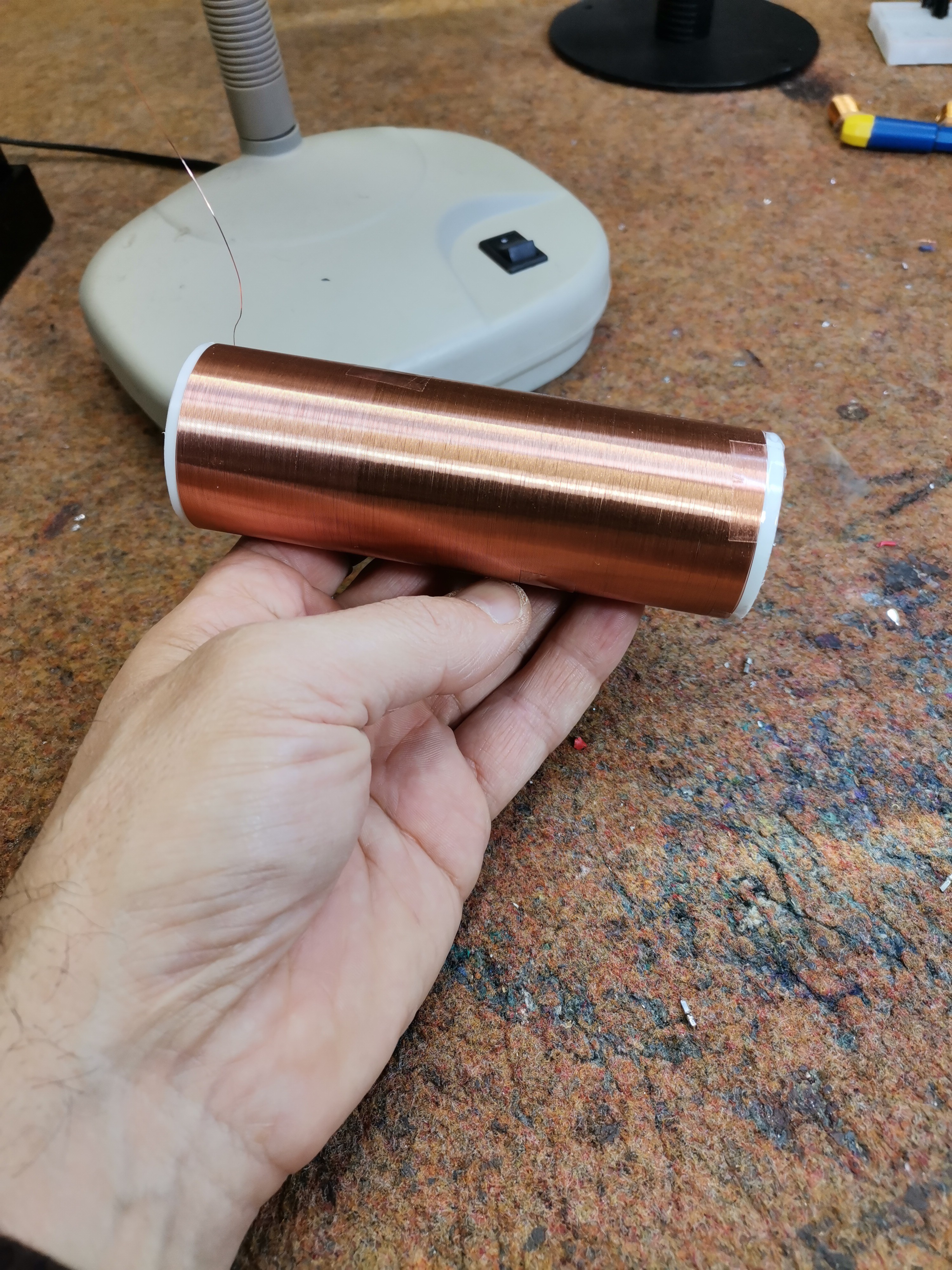
The secondary coil is wound on a plastic body with a diameter of 4cm and contains 520 turns of lacquered copper wire with a diameter of 0.2 mm. The height of the secondary is 12cm. The calculated resonant frequency of this secondary coil together with the topload is about 1.7 MHz.
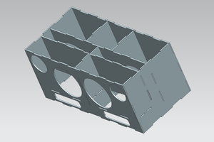
For a topload I use a small aluminum box.
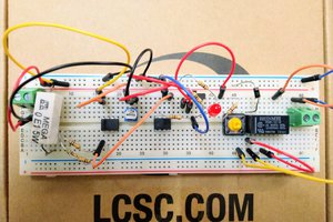
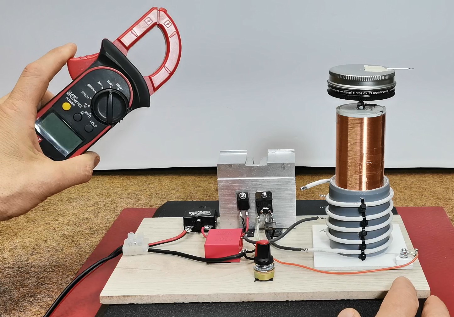
The power mosfet is specifically an BUZ325, but during testing I successfully used an IRFP460 which is also significantly more powerful. For voltages up to 60 V, IRFP260 can also be used. Of course, the mosfet should be mounted on a massive aluminum heatsink. The rectifying diode should be designed for a current of 5A or more, in this case I use a fast diode of the type U1540. A fuse is mandatory because relatively high voltages and currents are involved. It is very practical to use an automatic fuse as in this particular case. For the sake of constant monitoring of the operation of the circuit as well as the consumption, it is desirable to place a current clamp at the input.
The transformer that I use is taken out of an old defective audio amplifier
Now a few words about the first turn on and testing of the device. The best option is to use variac if we have it. The variac is actually an autotransformer where we can continuously change the voltage from 0V to the maximum value.
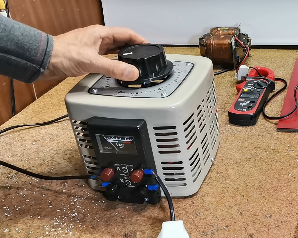
First, we turn on the transformer at a lower voltage so that it outputs about 15V. At start also we need to connect the primary coil with the most turns.(5 in my case). Next, with a fluorescent lamp close to the secondary, we slowly turn the potentiometer to the right....
Read more »
 Yann Guidon / YGDES