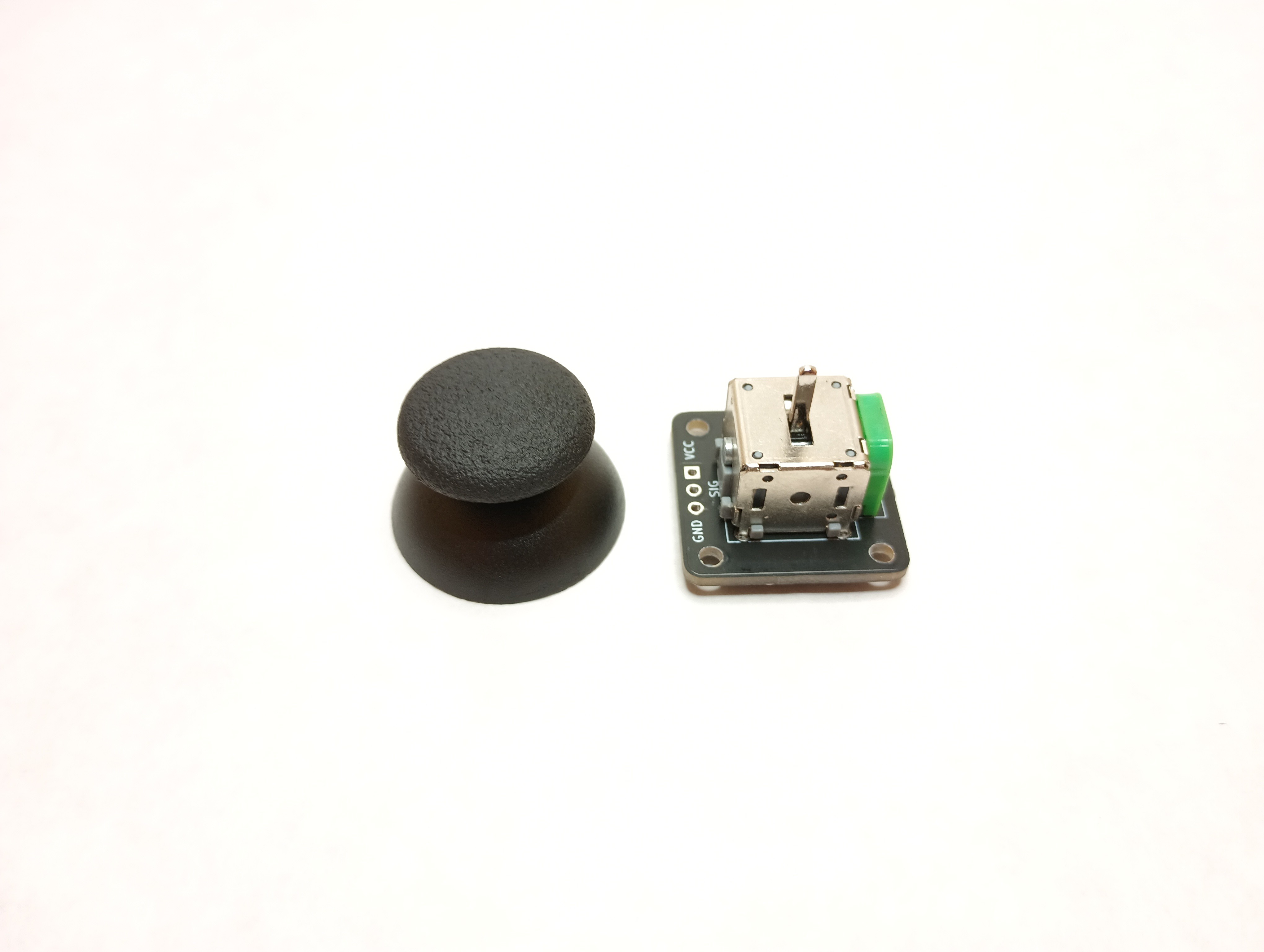
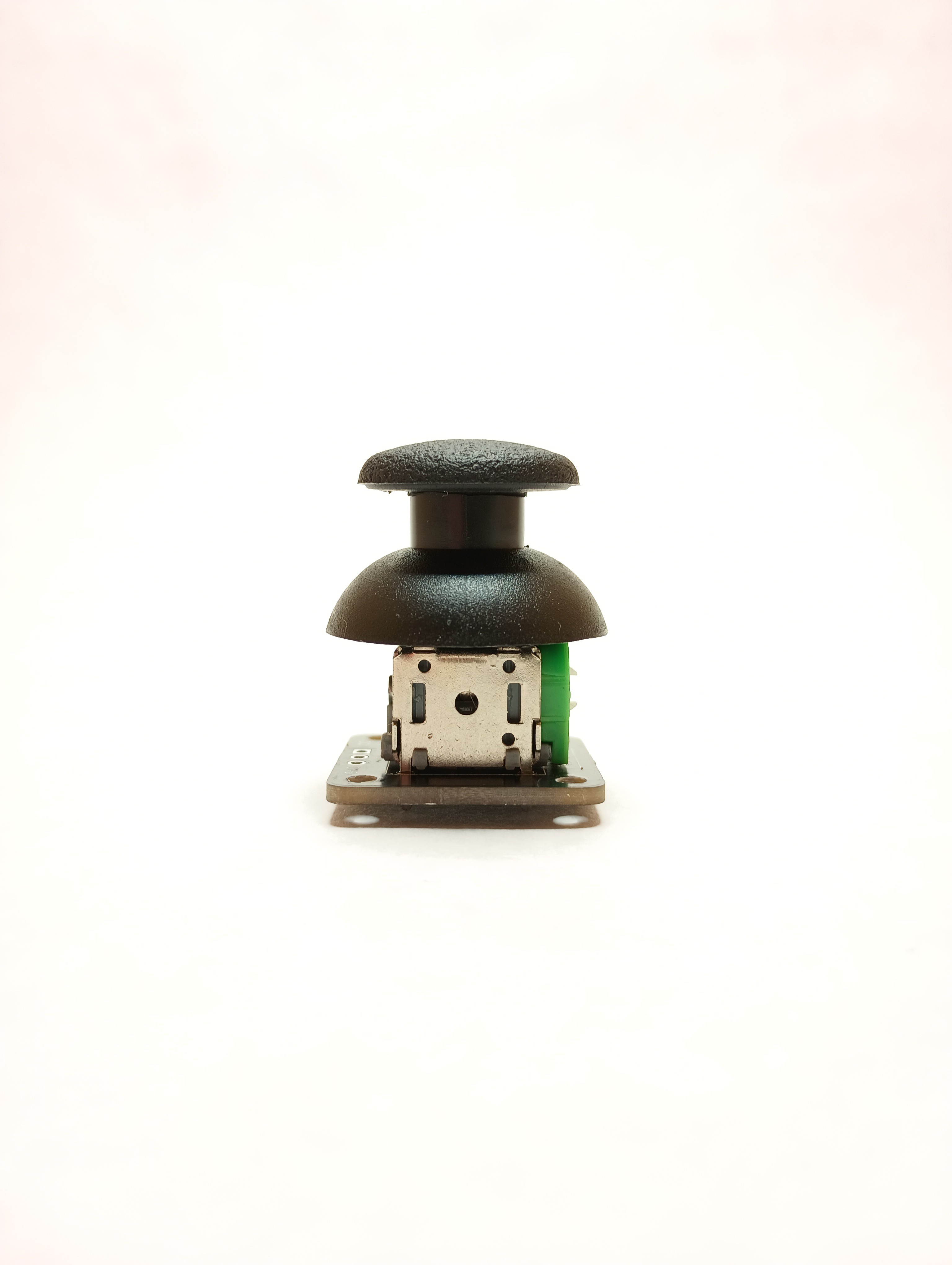
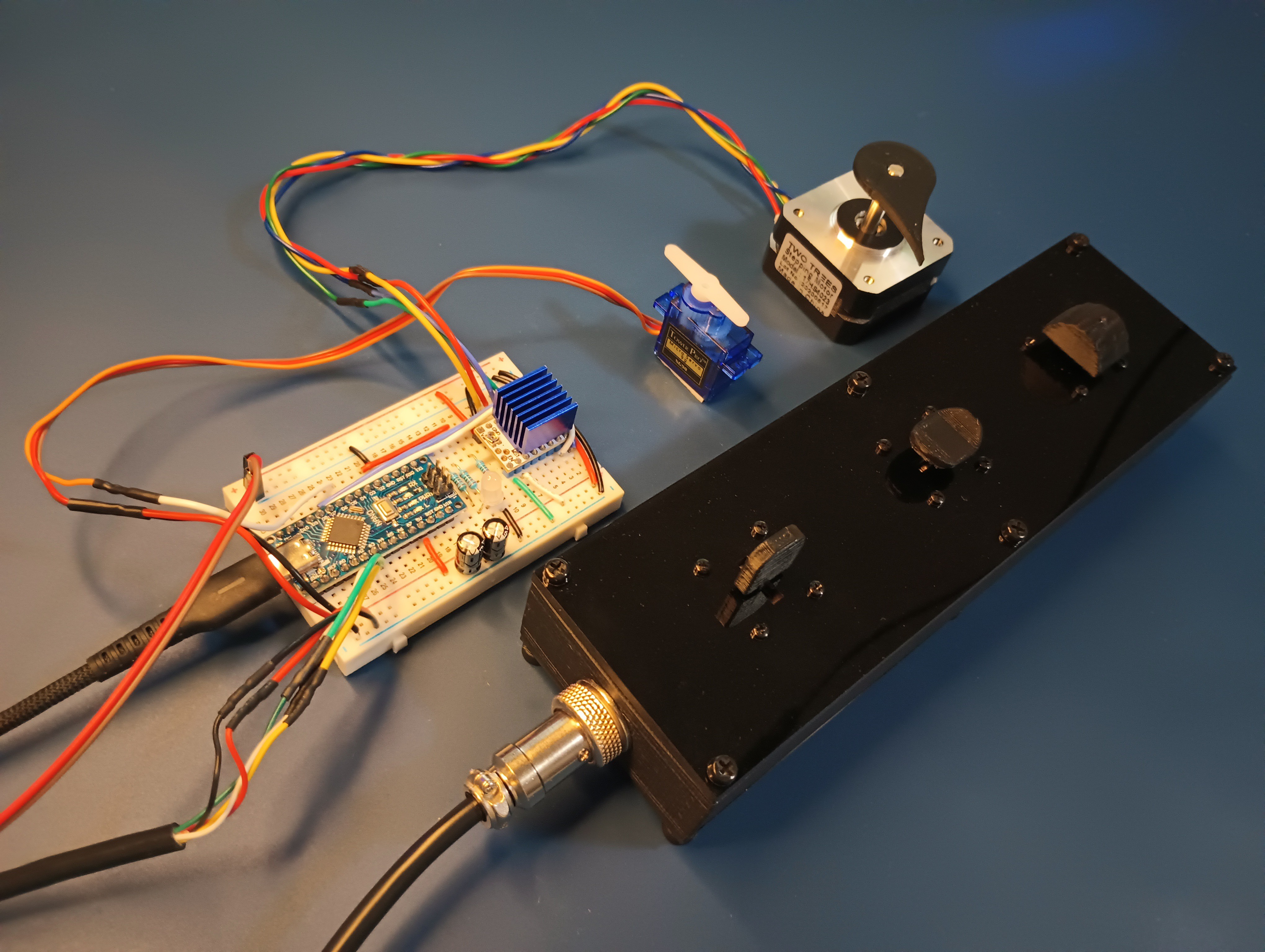
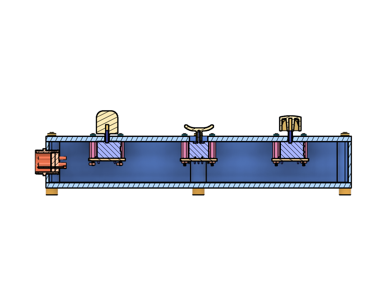
• 1
    Introduction

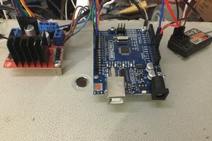
    In this project, I demonstrate three different use cases for single-axis joysticks with an Arduino Nano microcontroller. The joysticks used in this project can be found here!

    Single-axis joysticks have historically been out of reach for hobbyists due to their large size and high cost, and while dual-axis joysticks are ubiquitous and commonly available, sometimes a user just wants to control a single axis. For example:

    • Controlling the light output level from an LED
    • Setting the angle of a rudder, airfoil, or RC car's steering angle for hobbyist projects using a low-cost SG90 servo motor
    • Jogging the position of a stepper motor on a DIY CNC machine

    In this article, I share a demo unit that utilizes 3 x single-axis joystick module breakout boards to demonstrate these three applications!

    Disclosure: Some of the links in this article are affiliate links. This means that, at zero cost to you, I will earn an affiliate commission if you click through the link and finalize a purchase.

  • 2
    Electrical Hardware

    Solder the 22 AWG hookup wire to provide power (VCC, 5V) and GND to each of the three single-axis joysticks in parallel. Run one wire to each of the signal pads on each single-axis joystick board, and solder all 5 x wires to the aviation connector mounted on the side wall of the demo enclosure.

    Build the breadboard circuit for the Arduino Nano clone board as shown in the image. The pin connections leading to the Arduino are as follows:

    • D2: LED Red
    • D3: LED Green
    • D4: LED Blue
    • D5: Servo PWM Signal
    • D7: TMC2208 STEP
    • D8: TMC2208 DIR
    • A0: Joystick 1 Signal
    • A1: Joystick 2 Signal
    • A2: Joystick 3 Signal

    The Arduino Nano receives its 5V power from its USB port, which you can connect to a 5VDC external power supply, or to a typical PC/laptop USB port. The stepper motor is run off an external 12VDC power supply, and controlled using the TMC2208 stepper motor driver. Take care not to connect 12V positive power to any of the Arduino pins, or you risk damaging the Arduino!

  • 3
    Mechanical Hardware

    The demo unit was created by laser-cutting sheets of 1/8" thick black acrylic. The DXF file used to create the laser cutting files was made using Autodesk Fusion 360. The side wall of the demo enclosure was 3D printed using black PLA filament, and then M3 threaded inserted were installed around the top and bottom rims using a standard soldering iron. Some screw caps were also printed using black PLA filament for the demo unit to rest on. The top 3 x joystick caps were designed in Autodesk Fusion 360 and printed using the same PLA filament, and they were designed to be press-fit onto the joystick handles.

    The three styles of joystick I demonstrate here are:

    • Paddle type, for controlling the color and brightness of the RGB LED
    • Cup/trigger type, for controlling the position of the servo motor, e.g. for hobbyist RC boats, planes, and vehicles
    • Thumbstick type, used for jogging the position of a stepper, brushed DC, or BLDC motor

    The top and bottom laser-cut acrylic sheets are fastened to the 3D-printed enclosure wall using M3 screws, and M2 standoffs + screws and nuts secure the 3 x joysticks to the underside of the top face of the demo unit. A 5-pin aviation connector is mounted to the side of the demo's printed enclosure wall.