09/04/2024
Removing how skateboard "skin" was necessary to remove all the screws and components currently attached.
Here is a picture of the disassembled board, down up.
 Up-up view
The main issue come from the motor section, in theory it's only held by three screw with hex socket. But for two of those, the hex is more of a circle. Removing of said screw was made harder by the very tight grip it seem to have been manufactured with/somehow strange other factor due to it's long time in storage, and a position that make access hard due to the hanger being in the way of the potential Allen key.
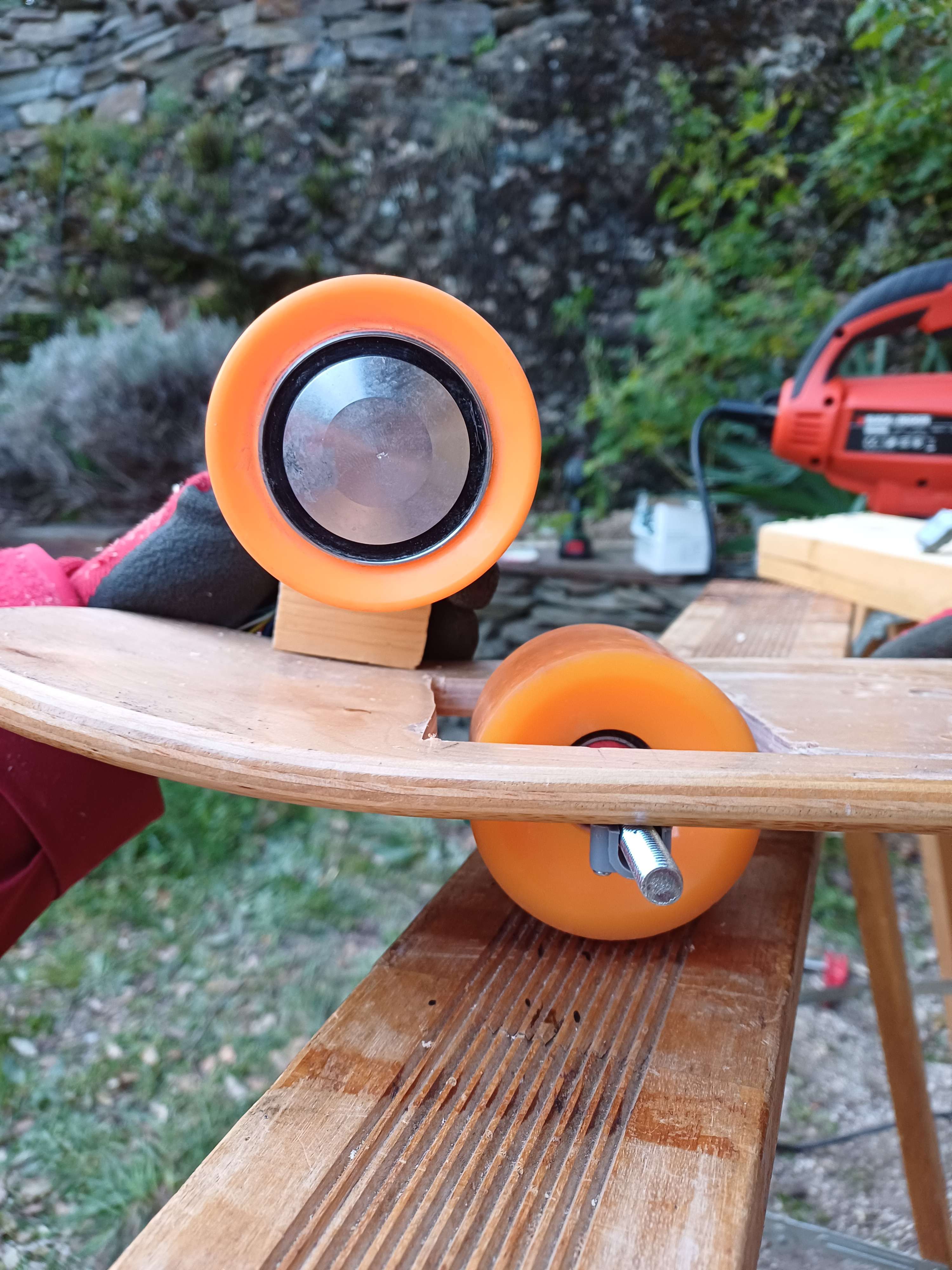
Due to theses factor and the fact that hanger aren't necessary or part of the project, since the wheels will need to be place on board level to be able to touch the ground even upside down as showed here:
With hanger:
Without hanger (axis going through the board or directly on it :
Neither are at scale since the board 3D model isn't accurate and we wheel model is outdated.
Thus:
We cut the hanger.

Removing those circle-screw is still going to be hard, we tried to make a cut in them to insert a flat screwdriver with no avail.
It's also possible to forgot about this problem as long as the hanger still attached to the motor is attached to the board.
16/04/2024
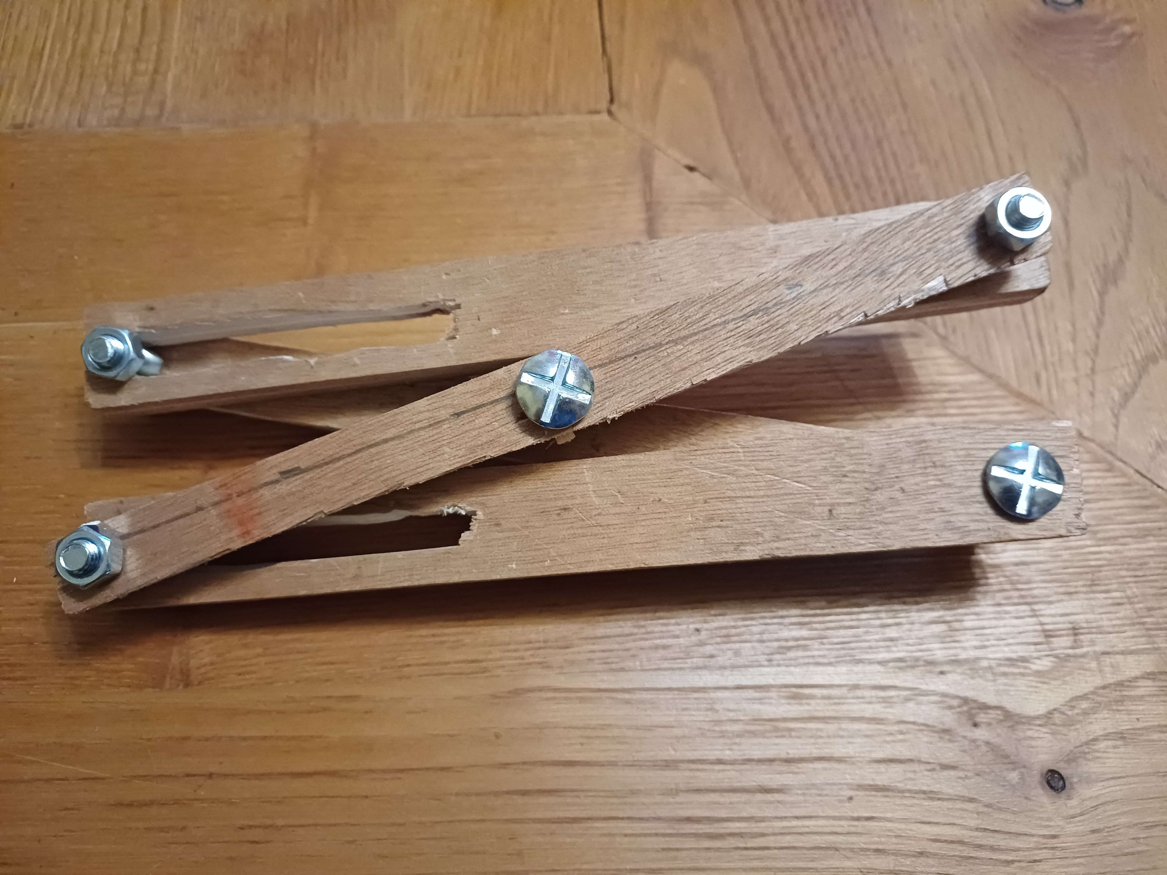
Printed (Laser-cut would have been easier but machine wasn't available) a pattern to cut wood to make the following system to lift one side of the skateboard.
Pattern:
 The mechanism is a combination of the these, with the first one creating the horizontal movement necessary for the second one to work and lift the structure.
First (1:40):
Second:
Also bought 20cm beam that will be used as axle.

Wheels can be maintained in the same position while still be allowed to spin.
Will cut the board place the wheels along the center of the board and try to free the motor from it's wheeled prison.
17/04/2024
Was able to make the lifting mechanism but making gears by hands (and electrics tools) is not easy. Will probably wait for laser cutting to be available.

We found a way to finally free the motor, a steady pliers and a drill were required.

The internal access main benefit was the possibility to drill a hole through the ball bearing to allow the axle to be installed creating a steady connection between the motor-wheel and the main body, with a bit of tinkering maybe offsetting the cable would permit having symmetric axle (it can't be a singular one since the motor is in the way.)
"Worst case" scenario was the impossibility to remove the cable and needing to enlarge one of the hole that was previously housing the problematic screw, putting an offset axle through it and accepting the less symmetric but working solution. The offset wouldn't affect the movement since its connected to the stator, which doesn't move.
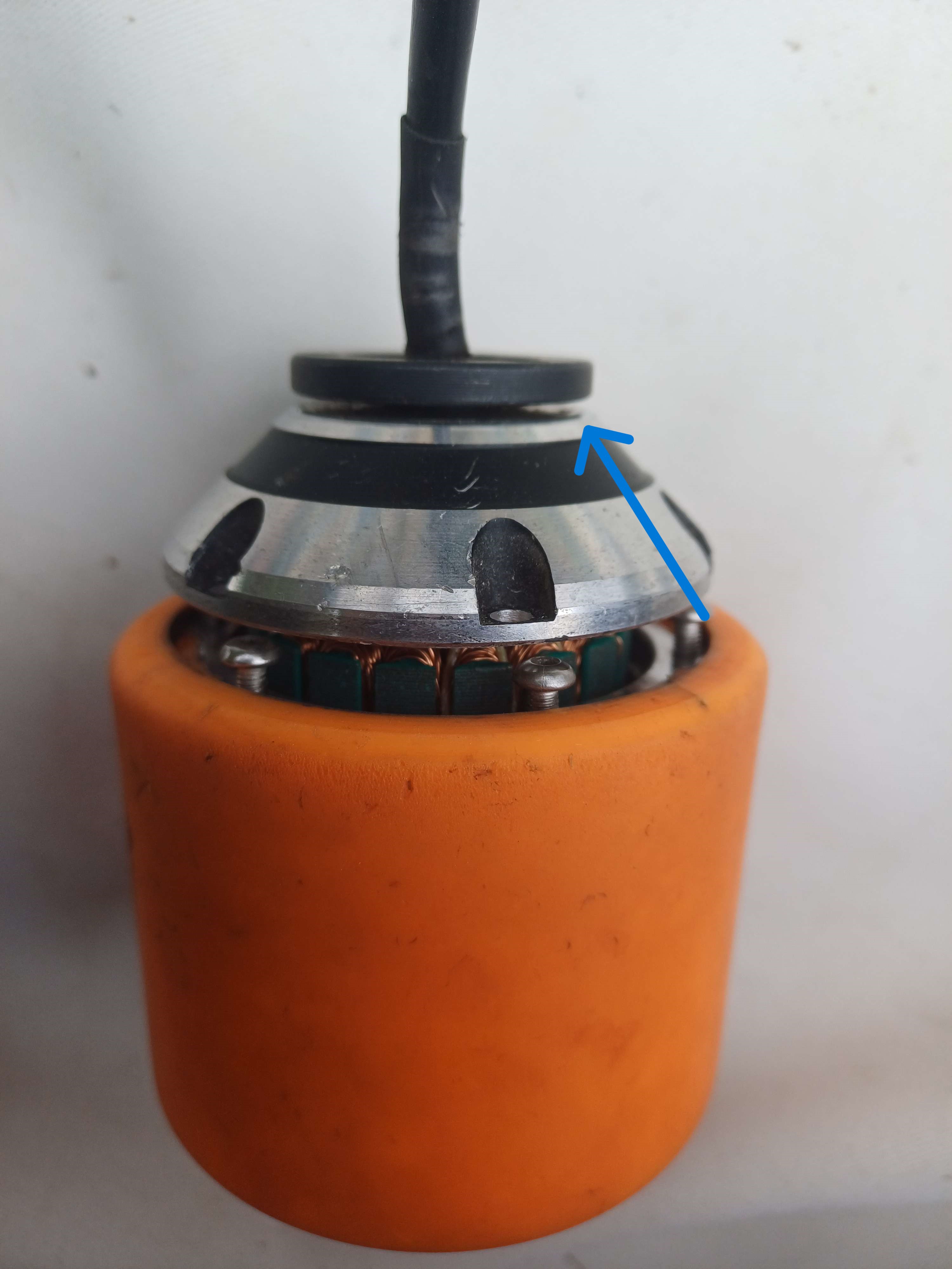
But really proved worst than the worst case, the casing (on either side) is harder than the metal drill we have. Here is a picture of the outside part of the casing as a showcase.
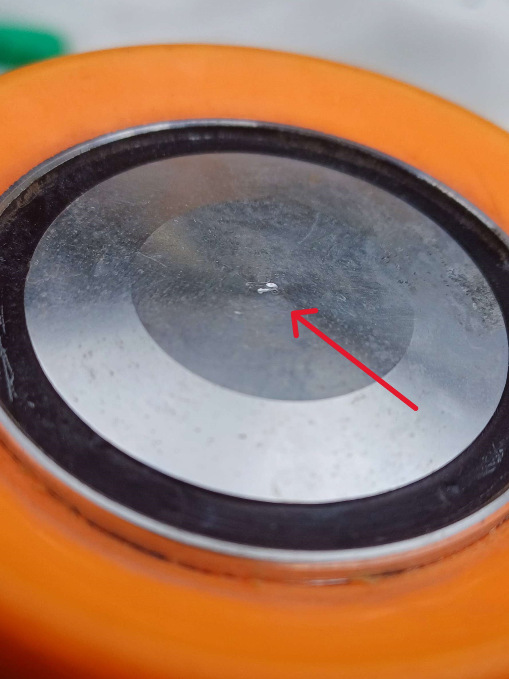
Also the case for this part (see blue arrow), preventing a clean body-axle-motor connection since even the currents bores can't be enlarged.
We will either need to find really longs screws (probably a bit weak, especially if it's only on one side of the wheel and the diameter is quite small), weld the axle (sub optimal for the safety of my fingers and above my pay-grade), glue (too weak) or find a better drill (may be hard depending on the material).
The idea of putting the axle through the body was abandoned due to risk of permanent structural damage to the skateboard, thickness of body is only a few mm greater than axle width. We will install it on the board instead, see pictures as reference.
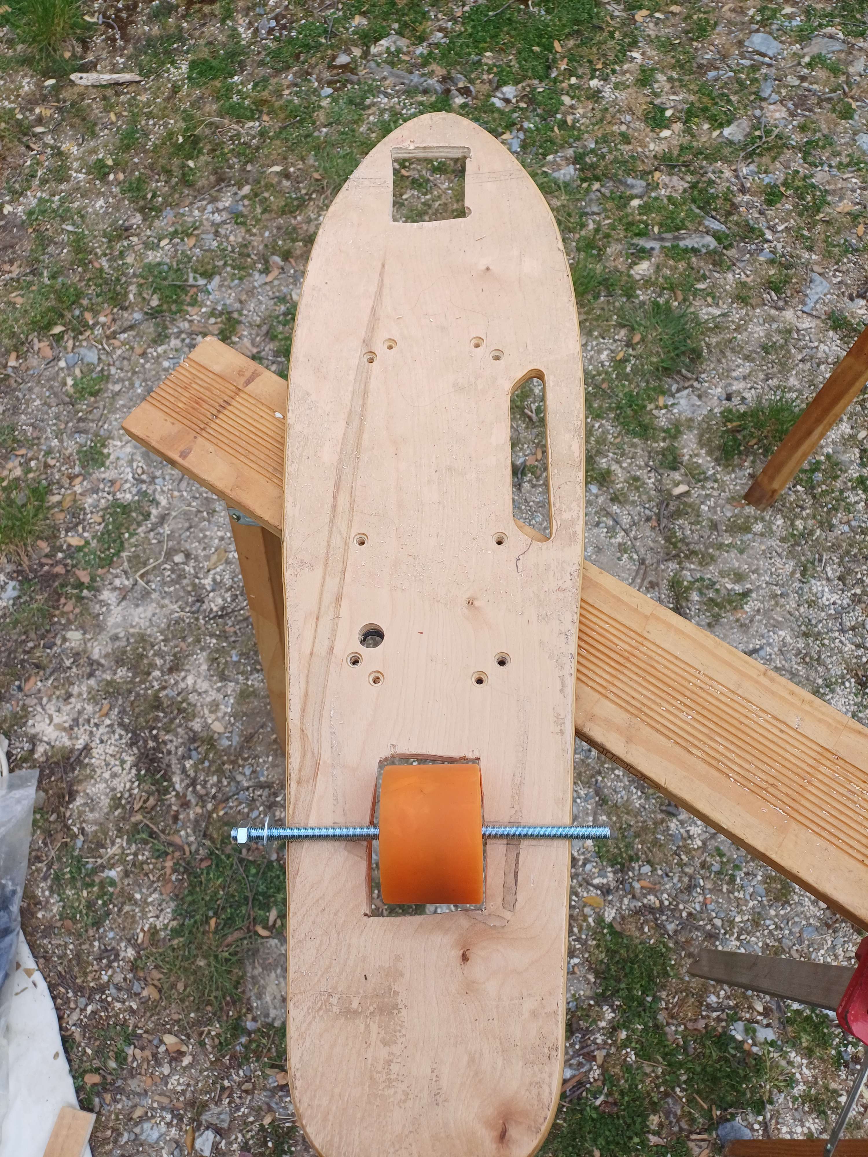
Wheels will still be able to touch the ground on both side. Axle could be maintained using small wood blocs but we should be able to buy something cleaner for cheap tomorrow. We will also need to enlarge the wheel-hole in the board for the motor to fit and look into what the casing is made of.
We will wait until we have access to the lab, buying a whole new cobalt bit (current one is HSS) to drill 2 holes seem expensive. We will also try to install the "air-propulsion system", really a high-pressure bad-idea deal tomorrow if possible.
We also gained a follower, should we celebrate ?
18/04/2024
Slight hail delayed progress.
Spider decided to build a small web in front wheel hole, even caught a prey.
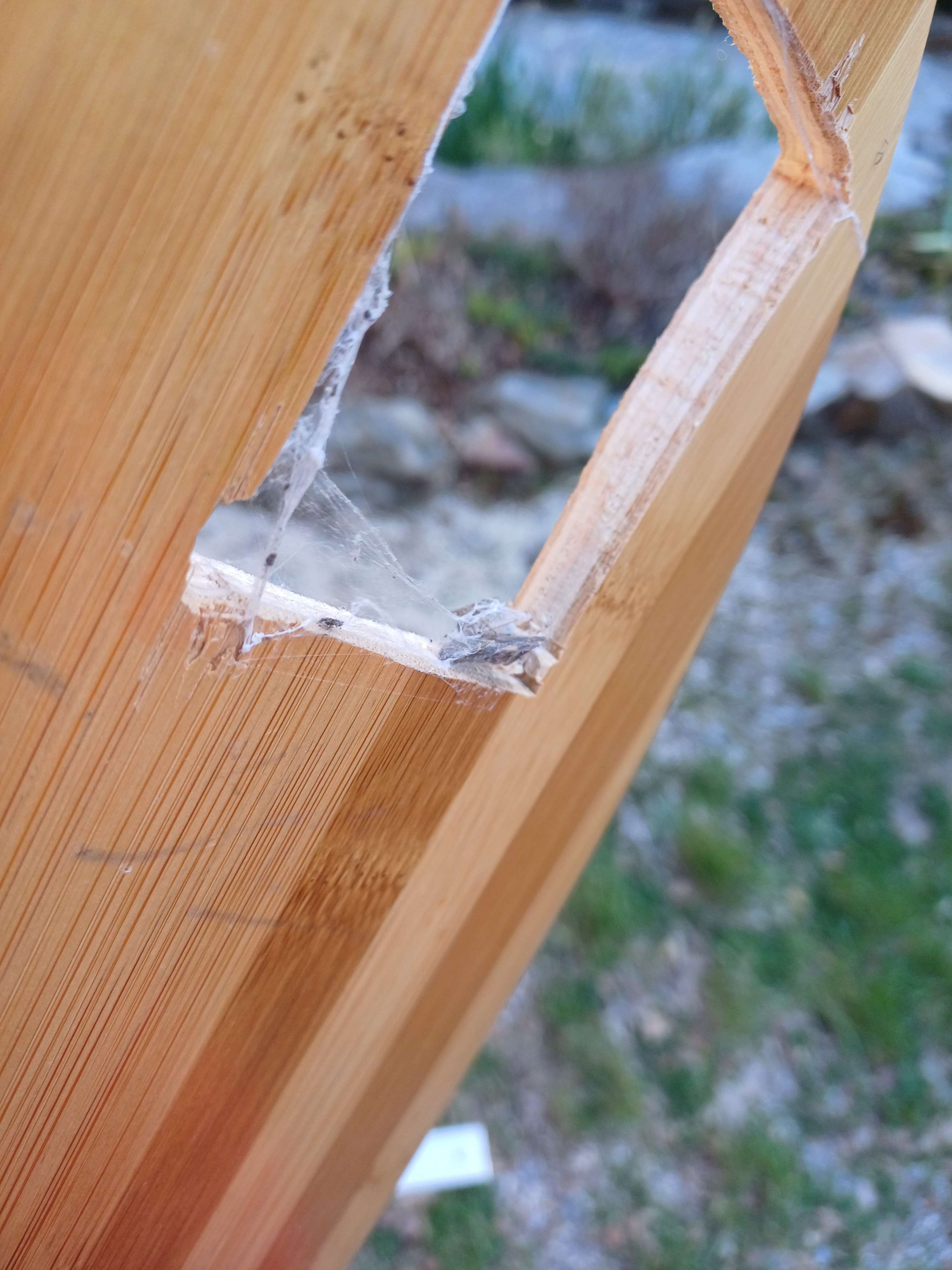
Web was removed.
Added 2 holes per parts of the lifting mechanism in order to change the effective length of the the lifting arms, allowing the overall structure to retract completely and be smaller.

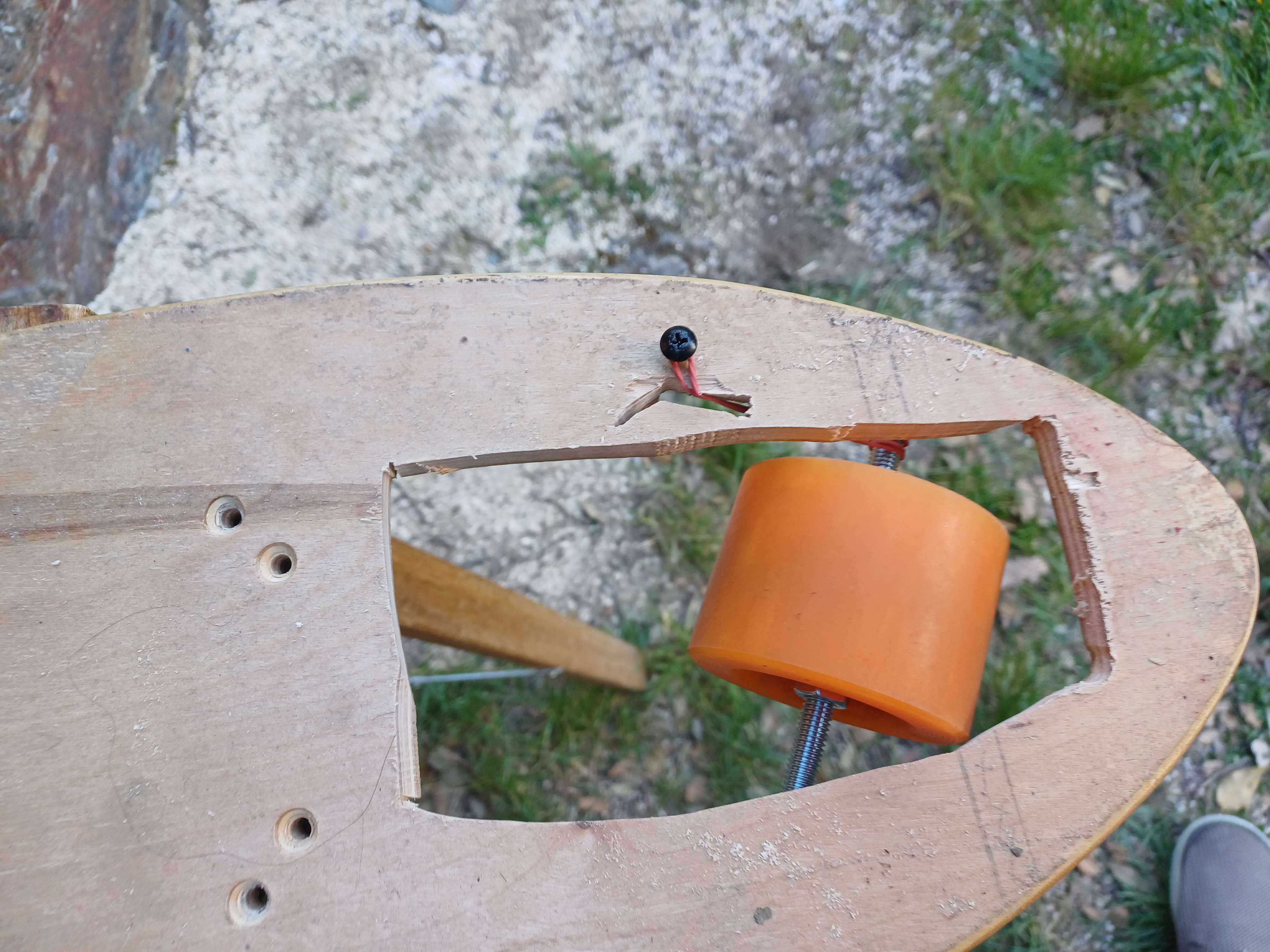
Made the hole of the front wheel larger and only fixed on side to create a steering wheel. Currently held in place with rubber band on the other side, enough for now but could be replaced with something beefier later.

And steering.

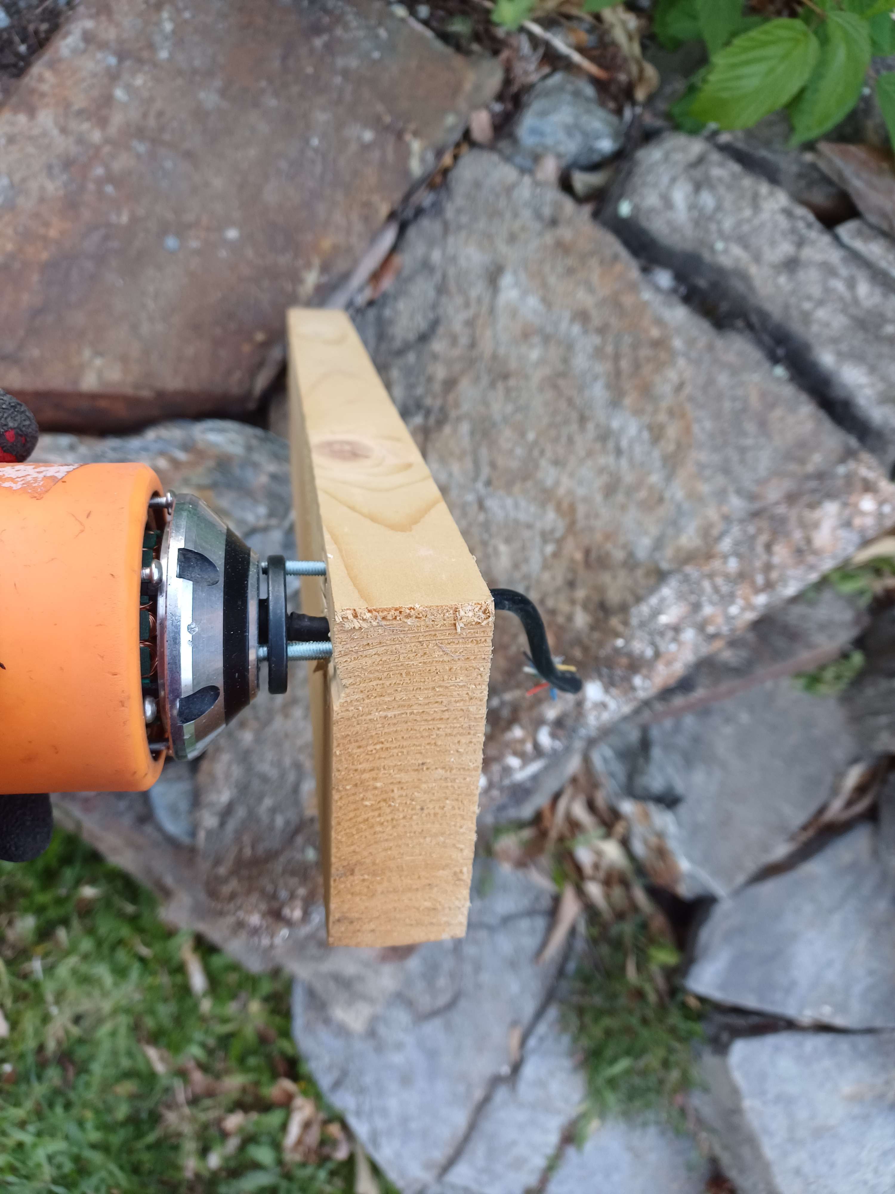
We found some long screw with just the right diameter to fit the motor-wheel. But the board isn't thick enough to fit them directly.
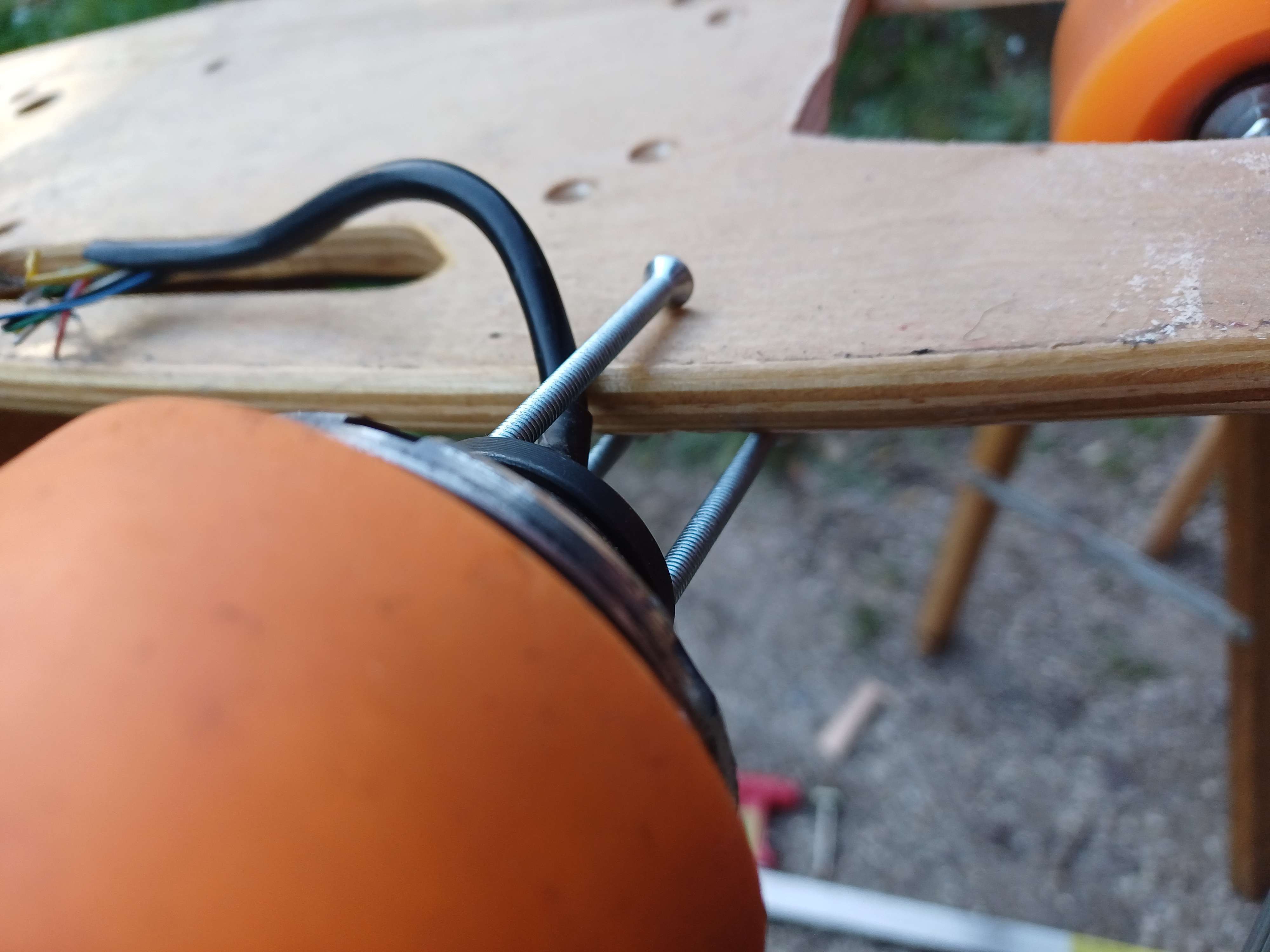
We made a square.
Also tried to make some progress on the air-mechanism to no avail.
Here is the general idea:
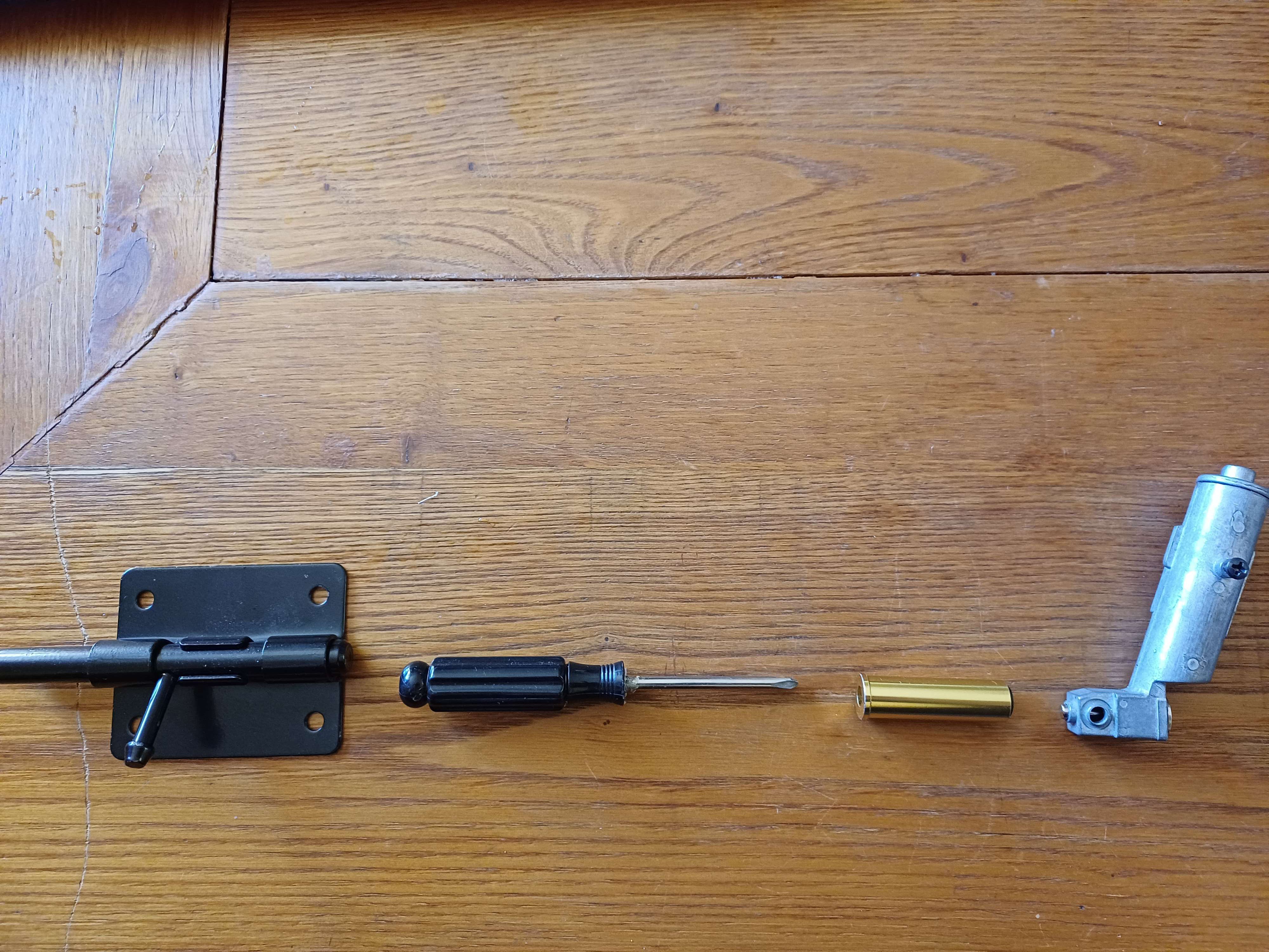
Note: We are currently missing a spring that will be placed to the left of the barrel bolt.
The horizontal movement created by the yet-to-be-cut shaft can also be use to slightly lift the barrel bolt, allowing the compressed spring to strike the screwdriver which is guided by an airsoft revolver cartridge to the gas chamber (from the same airsoft revolver), opening it and releasing around 7 cubic centimeter of compressed air at around 200 PSI (13,7 bar) through the hole facing the camera, which should hopefully be enough to make the last 30° necessary for the skate to make the flip.
In case someone is reading this log as an inspiration to make something else or similar, don't, high pressure are dangerous and you aren't meant to blow the entire content of a chamber in an instant in a not so regulated way. See example below as to why it's a bad idea.
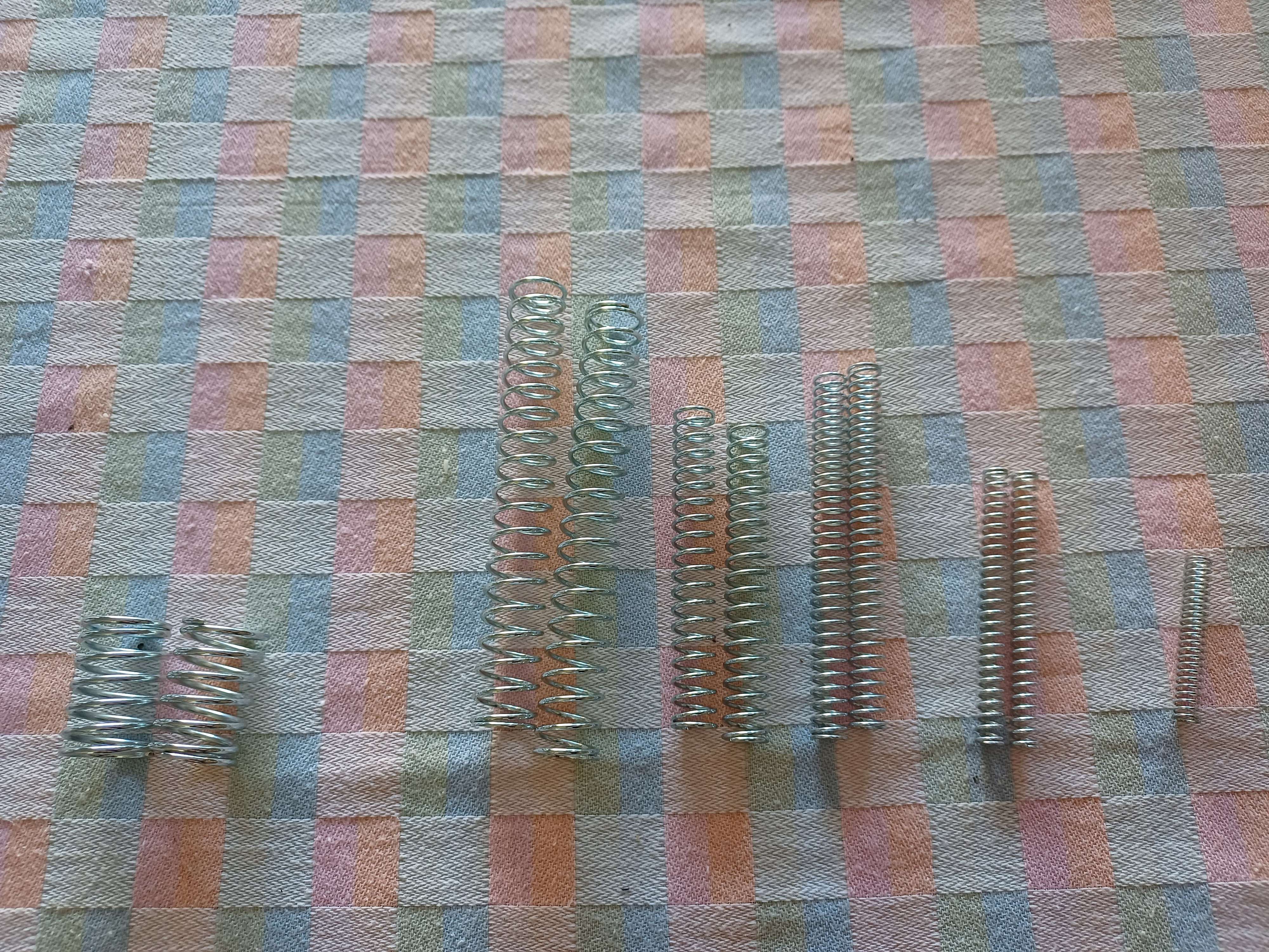
Note: Finding a adapted (or at all) springs is apparently harder than though since it's not a common part in small ironmongery.
19/04/2024
Got a 1 meter 14mm external diameter steel rod, with an approx 12mm hole drilled in the middle. The barrel bolt fit neatly in the rod.
We also got a spring package (was less expensive than just getting the right one somehow) with a couple that could fit perfectly in the rod and apply pressure on the barrel bolt, engaging the mechanism described yesterday and allowing the gas-chamber to be opened quickly.
We tried to test it, but needed to cut the rod to an appropriate length to block one send and compress the spring.
Note: Steel can't be cut with a hacksaw.
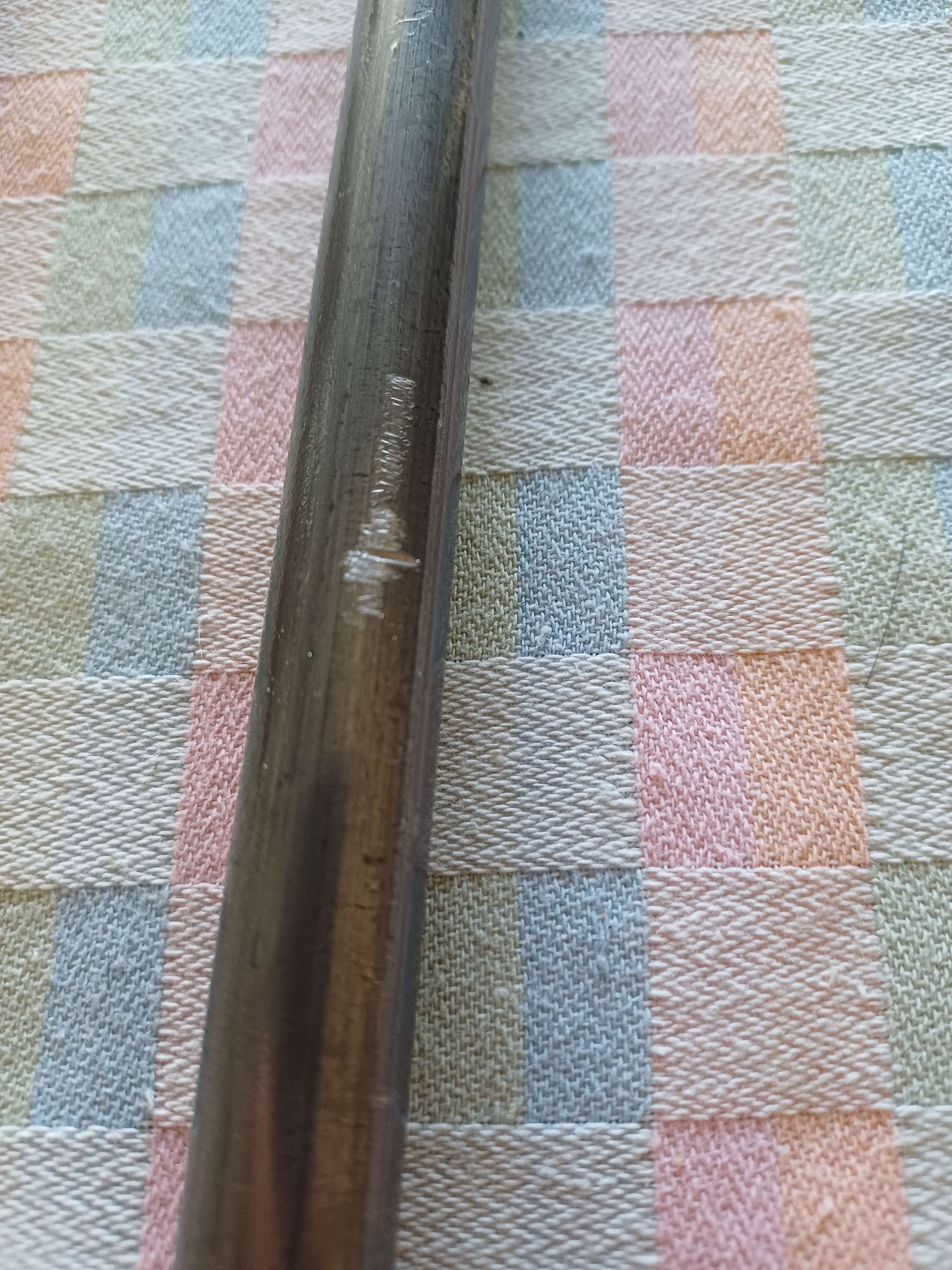
It's hard to notice on a picture but the teeth were filed away. Left arrow is toasted, right is not.

Discussions
Become a Hackaday.io Member
Create an account to leave a comment. Already have an account? Log In.