This is a gantry design that I came up with about a year ago. I figured out the kinematics and I hope to use it on my next 3d printer. I am going to call it "Haq XY" for now until I can come up with a better name.
Why this design?
If you want a lightweight gantry for your 3d printer or other cnc machine that doesn't have any motors on the gantry itself, there are a couple options. One is the H-Bot/ Core XY mechanism that you can read about here. There is also a pen plotter style mechanism like what is used on the Ultimaker. Another design is the Sli3DR made famous by RichRap. I am sure there are a couple other kinematic designs out there that I can't think of, but these are the main ones.
The reason I came up with this design is because I have built both an H-Bot and Core-XY printer and although you can get great results with them (My main printer right now is Core-XY), you still need a very rigid/solid gantry to deal with the racking forces. Although Core-XY eliminates most of those racking forces, you still need a rigid gantry to deal with the belt tension. For instance, if one of your belts is slightly tighter than the other, then it will skew the gantry out of square. To overcome this, you usually need to make the x axis very wide and rigid so that it doesn't skew out of alignment. This can increase the weight of the over gantry however.
I also wanted to do something different and add another X axis. I am not always one to re-invent the wheel, but I also don't like to do something that has been done a million times. As far as I know, this gantry design is a new "novel" design; although there is something similar. More on that in the next section.
Has anyone done something similar?
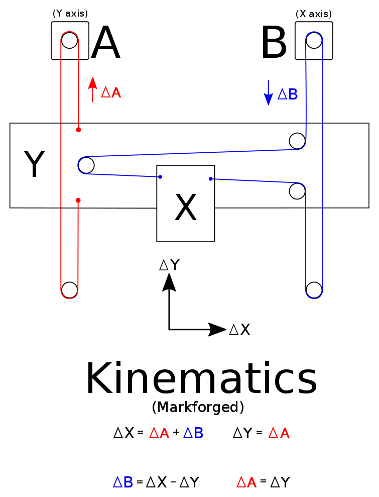
Sort of. It wasn't until a few months ago that I noticed that the Markforged 3d printer uses the same Kinematic design. The implementation of the kinematics (the gantry design) are different than mine, but mathematically the kinematics are very similar. I had to take a real close look at some still frames in a video to realize that it wasn't an H-bot like I originally thought. I did find this thread a couple months ago which talks about the kinematics of the Markforged, but I do like this novel approach over CoreXY. You can see a photo of the Markforged kinematics below.
What makes your's different then?
The big difference is that I designed mine to have 2 separate X axis compared to just a single X axis. This will allow either dual extrusion (similar to the BCN Sigma 3d printer) or better yet, 2 separate tools! Imagine having a 3d printer tool head on one, and a laser on the other, or a color inkjet printhead to color each layers perimeter (plus the top) and create full color 3d models. Another idea is to have a small brushless motor to act as a cnc router to do engraving (pcb's), or to do a finish pass along the important dimensions of the 3d printed model to make it more dimensionally accurate.
Another difference is that in my version the Y axis is designed to be constrained by a belt on both ends of the Y axis. Although the Markforged does encounter some racking forces, this design should counter-act those racking forces. It also allows me to have room for the 2nd X axis.

Implementation
Although I am not building my next printer just yet, I do have a mechanical design drawn out for the gantry and belt path design. In the image above the X axis belt paths overlap, and criss cross. I did this to better show the belt path, not to show how it would actually look. In reality the belts B1 and B2 would be at separate heights, and they would not criss cross each other. The idler pulleys on the x axis would also restrict the belt path to 90 degree angles instead of the weird angle that it is in the diagram.
Firmware
I was thinking about using Marlin for the firmware. Since these kinematics aren't implemented in any open source 3d printer firmware, I modified the core xy kinematics in Marlin for testing. I tested...
Read more »


 Alex Anderson
 theschlem
 Shane Hooper
 TTN
TTN
I have printer with this cinematic, can you get link to your source modification?