canique
Currently the 3D design is finished, and a first assembled device will be available in the course of April.
This Energy Meter Reader is planned to be used with the ultra low power sensor: https://hackaday.io/project/186949-canique-ambience
The complete setup will allow to read energy usage in short intervals, say 15 seconds, transmit them via UART to Canique Ambience, which then parses them and sends them via 868MHz to a base station.
The big differences between this design and available products on the market are:
- No necessity for a power outlet. The energy meter adapter will be powered by the Canique Ambience sensor, which itself is powered by a standard AA battery.
- Good wall penetration and range. Unlike WiFi this radio setup can easily go through mutliple walls.
- Extremely low power. A single AA battery will be able to supply the sensor + IR adapter for multiple years. The expected total quiescent current for the sensor + IR adapter from a 1.5V battery is: 2.57µA
 Nikos
Nikos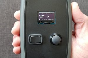
 strange.rand