 JP Gleyzes
MM2001 board
The most up to date documentation of this board can be found here : carte MM2001
This site is linking to original documentation that is no longer accessible. However I finished to grab THE zip file with everything inside. Here it is for posterity : original backup MM2001.zip
Compatible with most "french" foam cutter softwares this board is able to :
- drive 4 unipolar steppers
- drive a hot wire
- interface with parallel port to jedicut or GMFC foam cutter softwares
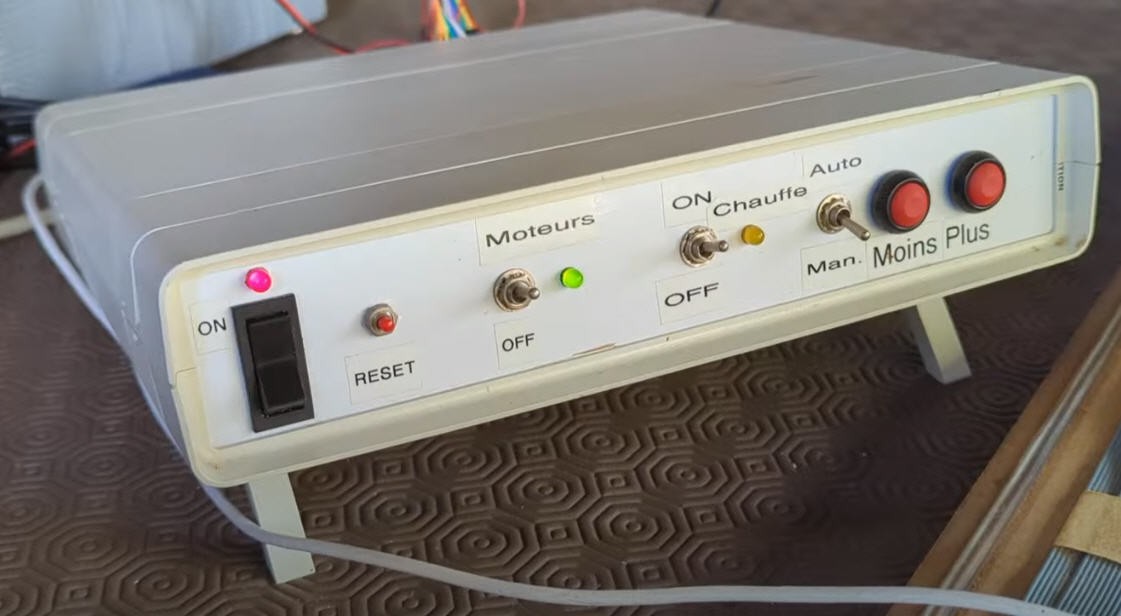
It offers possibility to start/stop motors and to control hot wire temperature either with PC or manually.
A new version of this board (mainly firmware update) tried to get rid of the parallel port interface and needed the use of a devoted USB interpolator. The IPL5X project did this trick and did it very well!
However I wanted to control my foam cutter as I control my CNC : ie with Gcode. And this wasn't offered by IPL5X. Even though this software is fully open source and documented, the MM2001HL board would be "linked" to IPL5X and to other compatible foamcutter softwares... I really wanted something more "standard" using Gcode files.
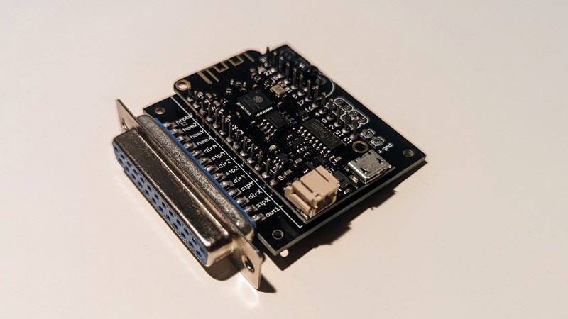
As I already made a // port to FluidNC board I did try to reuse this board to interface it to my MM2001 board.
And here is the result with my machine performing a "test cut"
MM2001 interface
MM2001 is interfaced to external world via the parallel port
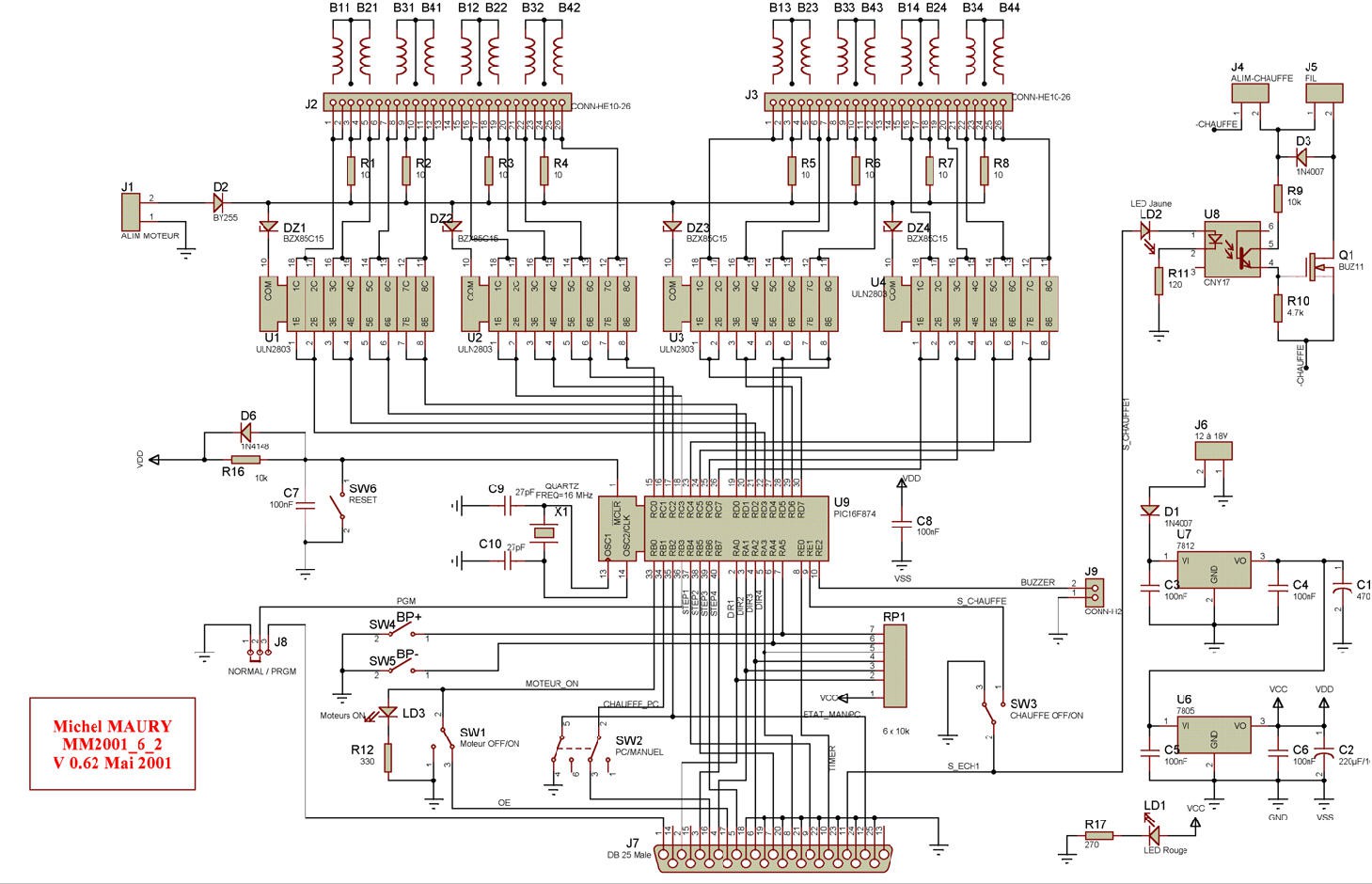
Here are the signals used:
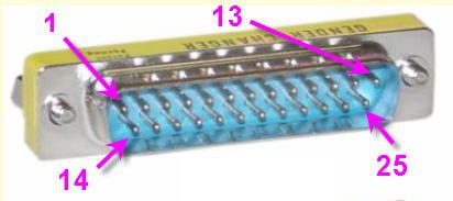
pins are number on the parrallel port seen from external side of the MM2001 (male connector)
The female connector on the ESP32 board is connected following this schematics :
beware that the pins names are those of the Mach3 CNC interface... So they are not exactly those of the MM2001 (but who cares) ?
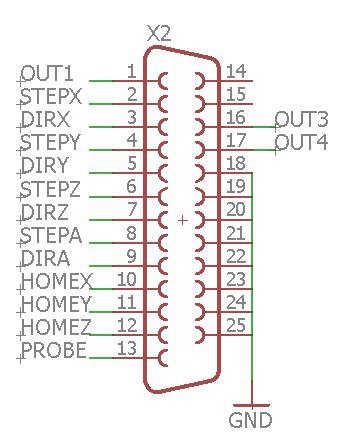
| function | parallel port pin | ESP32 pin/name | I/O | comment |
| Normal/PRGM | 1 | OUT1 | I | used to flash the firmware. Not used here |
| DIR1 | 2 | STEPX | I | Dir signal motor 1 (pull up 5V) |
| STEP4 | 3 | DIRX | I | Step signal motor 4 |
| DIR2 | 4 | STEPY | I | Dir signal motor 2 (pull up 5V) |
| STEP3 | 5 | DIRY | I | Step signal motor 3 |
| DIR3 | 6 | STEPZ | I | Dir Signal motor 3 (pull up 5V) |
| STEP2 | 7 | DIRZ | I | Step signal motor 2 |
| DIR4 | 8 | STEPA | I | Dir Signal motor 4 (pull up 5V) |
| STEP1 | 9 | DIRA | I | Step signal motor 1 |
| TIMER | 10 | HOMEX | O | Timer signal not used (do not solder this pin) |
| S_ECH1 | 11 | HOMEY | O | sampled hot wire signal (not used do not solder this pin) |
| status Man/PC | 12 | HOMEZ | O | manual/PC switch status (not used do not solder this pin) |
| NU | 13 | probe | X | not used |
| NU | 14 | NU | X | not used |
| NU | 15 | NU | X | not used |
| CHAUFFE_PC | 16 | OUT3 | O | monitoring hot wire. (Not used do not solder this pin) |
| Motor On/Off | 17 | OUT4 | I | enable motors. (do not connect works without this signal) |
| gnd | 18-25 | gnd | ground |
MM2001 modifications
Interfacing my board to MM2001 should be a matter of configuration... well almost!
A few very simple modifications were needed.
5V to 3.3V considerations
My ESP32 is a 3.3V device while the MM2001 is 5V compliant. So a light "level shifter" was needed.
As I only want to pilot 4 unipolar motors and to control the hot wire, I can simply ignore most of the internal complexity of the MM2001.
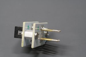
The only level shifter needed (and probably not mandatory... as it works without) if for the DIR signals of the steppers. These signals are pulled up to 5V into the MM2001 via the RP1 resistor network.
so to avoid to drain the DIR outputs of the ESP32 I simply decreased the voltage of this resistor network by adding a simple led between pin1 and Vdd.
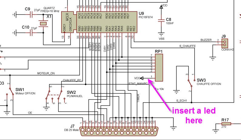
The 1.6V voltage drop of this led is enough to decrease the pull up from 5V to 5-1.6 = 3.4V which is safe for the ESP32.
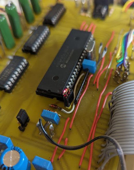
Here is the result. Easy modification insn't it ? (I mounted this led on a jumper to possibly go back to the original 5V)
Now it time to track any other signals which could need level shift...
- TIMER signal was used to send an interrupt signal to the PC to synchronize motors. This signal is not needed with FluidNC so do not solder this pin on the ESP32 connector to avoid inputing 5V into the ESP32...
- Status Man/PC : gives the status of the switch. Totally...
 Ben Mo
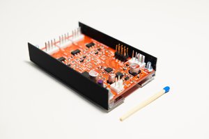
 t.oster92
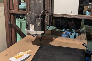
 Alpenglow Industries