First off, huge thanks to NextPCB for sponsoring this project.
Below is a quick text log of generally what I went over in the video in case you prefer reading:
So let's start with what an eink display (from here one referred to as EPD, ElectroPhoretic Display) is and how it generally works. EPD's are characterized by their high contrast, almost paper-like appearance, generally grayscale or monochromatic (though now color versions are starting to come out), lower operating power during updates and bistable image retention. On the downside they are quite expensive due to being patented technology and their refresh rate is much slower than other display types. Below is a crude sketch of the cross section of an EPD.
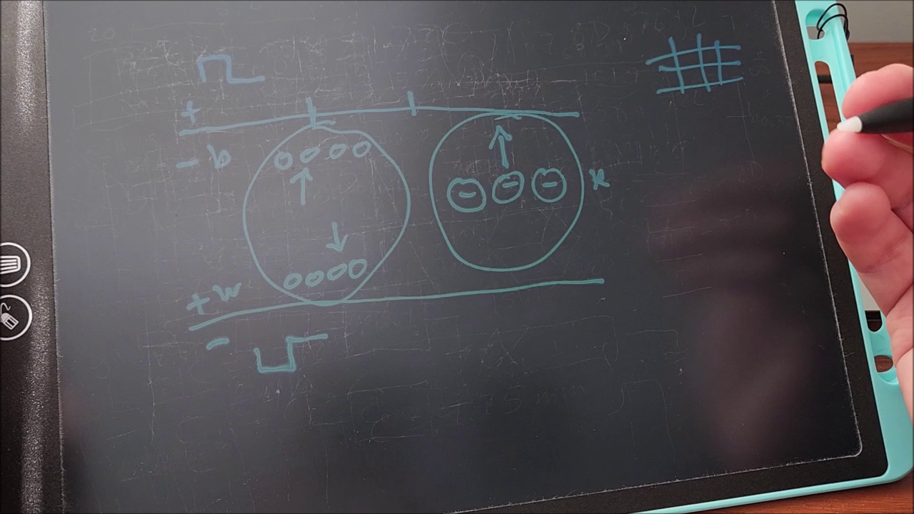
Here you can see that inside the EPD are tiny capsules containing clear viscous fluid as well as tiny charged pigmented balls that are black and white. The balls of each color are oppositely charged. On the top and bottom of the display are clear electrodes arranged in a grid pattern. When a pixel's electrodes are controlled with a positive and negative waveform on opposite sides the colored balls of opposite charge are attracted either to the top or bottom. The magnitude, polarity and time of the pulses can be tightly controlled through the controller. The pattern of the waveform is stored in non-volatile memory known as LUTs (Look Up Tables) inside the display controller and is a sort of "magic sauce" that many manufacturers wont disclose.
In order not to permanently damage the display by polarizing the materials in the layers and thus getting the colored balls "stuck" in either position the waveform is designed to average out the drive polarity so that there's a net zero charge balance. This is the reason that updates take awhile and there's multiple flashes of opposite colors and inverted frames in a full refresh. It's possible though to do a partial or quick refresh by omitting balancing frames in the sequence, at the potential cost of contrast, ghosting and display lifetime. I've yet to implement a quick refresh for my display but I plan on doing so to make setting the time much quicker and less painful.
EPDs with more colors exist which have additional larger colored balls, taking advantage of slower movement through the viscous fluid to make controlling them "independently" of the smaller balls possible. These however take even longer to update and grayscale isn't really possible so dithering is necessary.
So the first thing I did when I received the display was to design the pcb shown below.
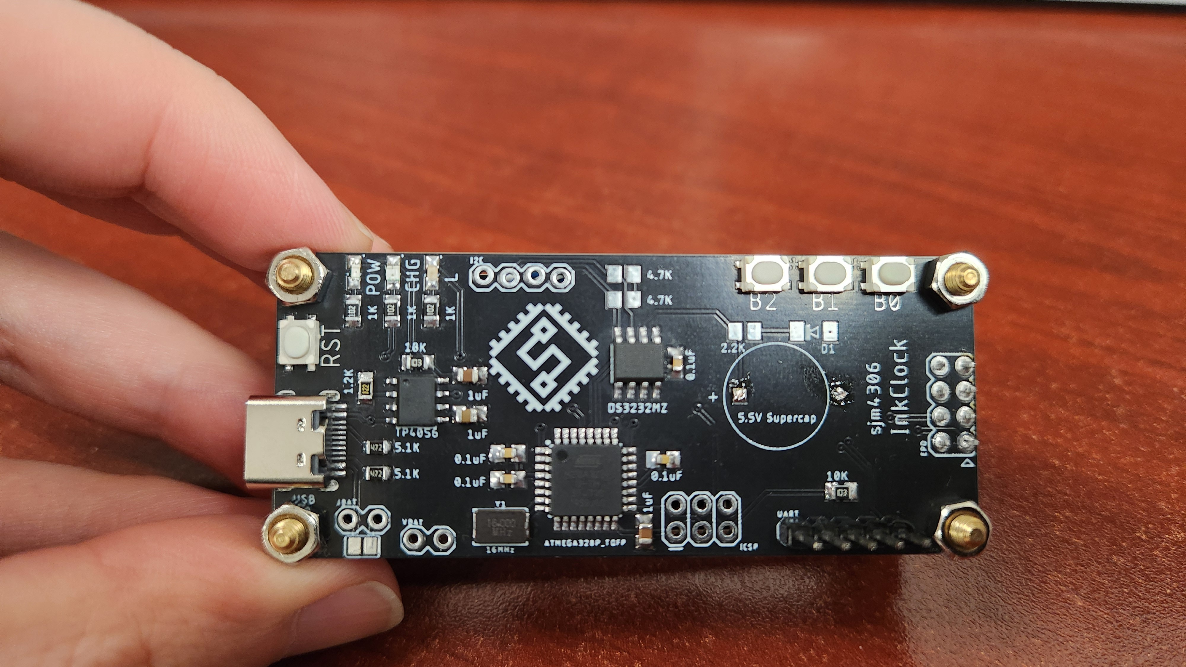
It has all of the required circuitry to drive the display, charge a lipo battery via USB C, keep time with an I2C real time clock chip, and finally a smattering of user I/O to control the clock. The microcontroller is the venerable atmega328p and with only 2k of ram it obviously cant double buffer the display, so my graphics library is written to run on smaller chips with limited resources. Next up was porting my graphics library to work with the new display. I referenced arduino test code provided by BuyDisplay (the manufacturer of the EPD module) to initialize the controller and then set about tweaking my code to update the new display. Below is some demo graphics and fonts showing what my library can do.

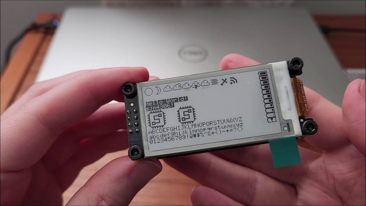

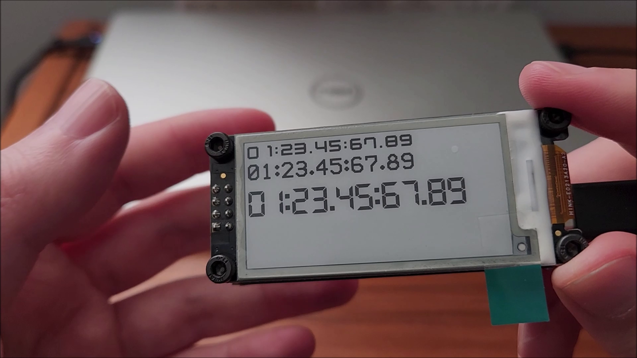
I've implemented bitmap and string support along with multiple fonts.
So there was one major mistake I made, when I designed the pcb footprint for the USB C connector I used I forgot to isolate the bottom layer mounting pads so when I set the top plane on my pcb to ground and the bottom to vcc I inadvertently shorted the two together. Luckily I realized this before powering the board up the first time and was able to use my cnc to isolate the bottom pads from vcc. This route is visible on the bottom pcb to the right, just under the USB C connector.
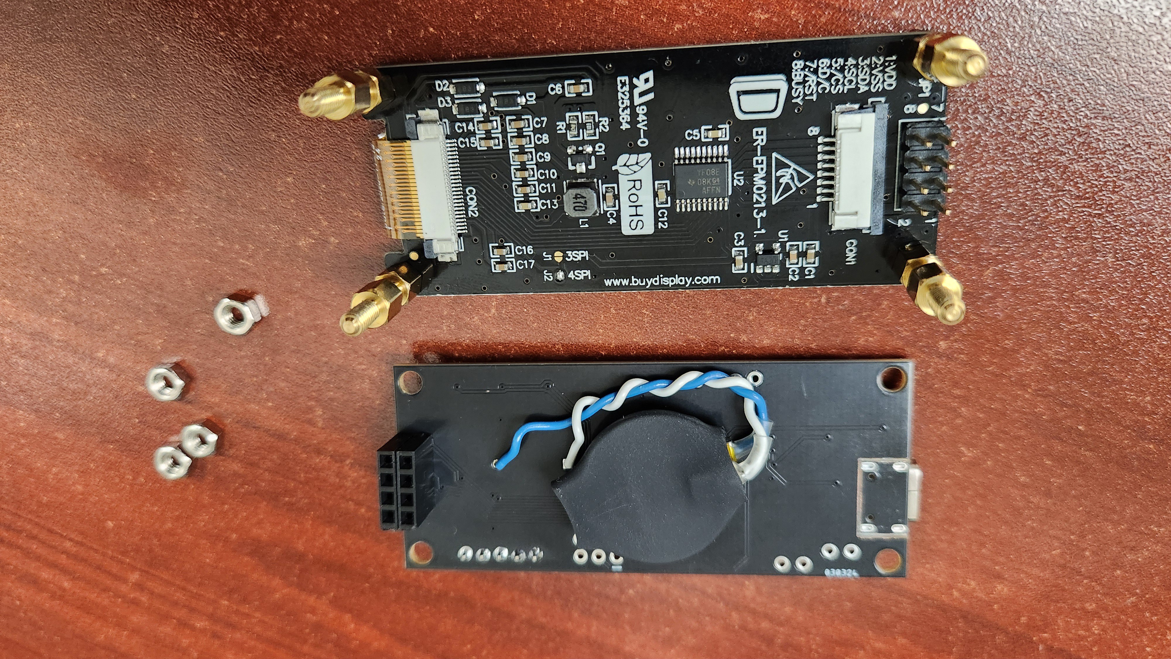
Above you can also see the small CR2032 I'm temporarily using to keep the RTC time while the clock is unplugged.
So in the end here's the GUI for the clock.

The main display shows the time in large 32 pixel high numbers with an AM/PM indicator. Below is smaller 14 pixel high text showing the day of week, month, date and year. To the bottom right is the battery indicator and percentage (using the fantastic CPUVolt arduino library which calculates mcu supply voltage with the use of the Atmega's internal reference voltage).
To set the time I implemented a simple menu system.

Up and down buttons advance the selected option to change and holding the center button while clicking up/down a desired number of times will increment/decrement the selected value. The display is only updated when the center button is released. This gets around the ~1-1.5 second refresh time of the display till I can implement a quick refresh for the display.
Additionally I've added a feature that inverts the main time display colors during nighttime.
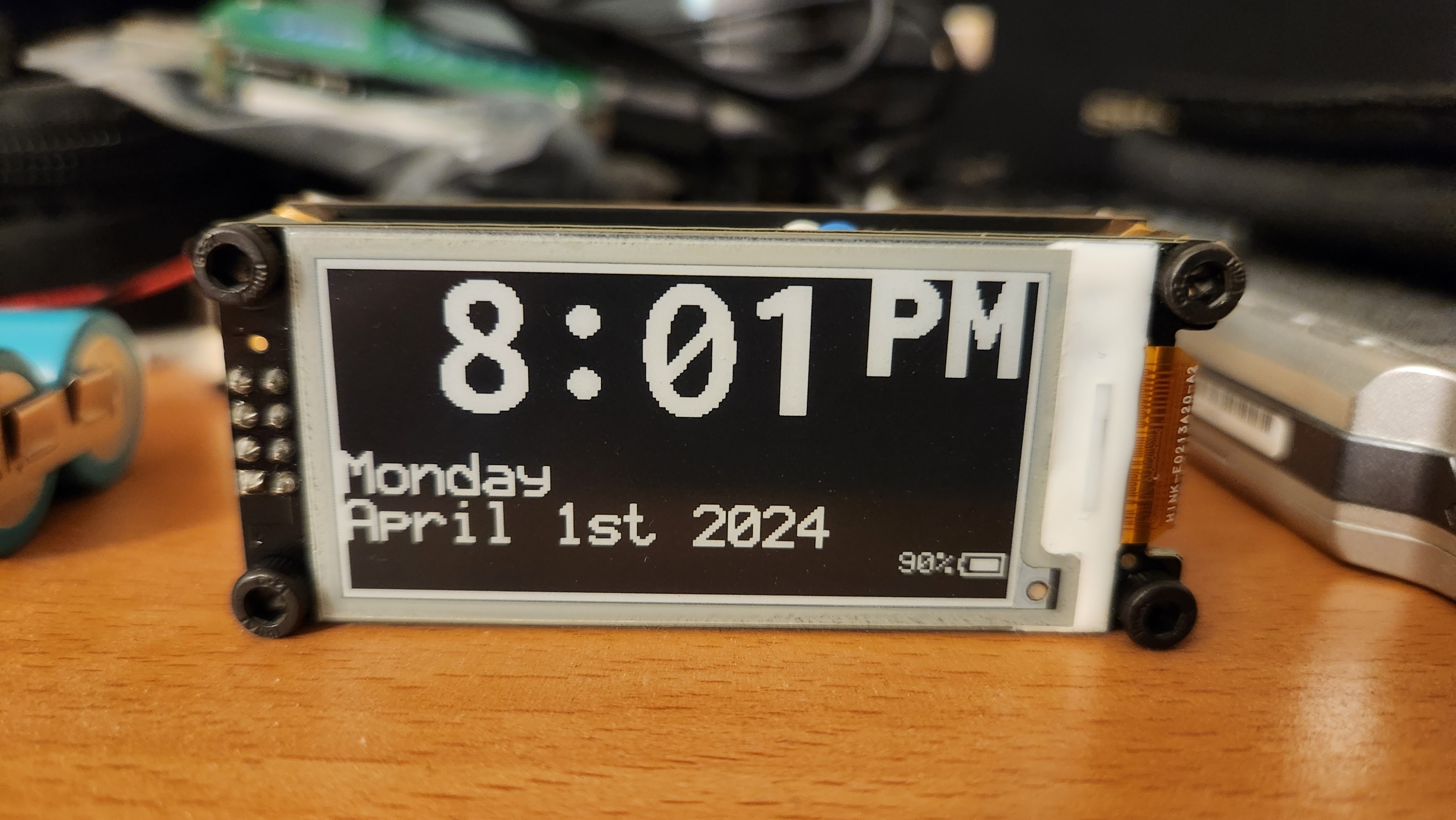
I'm currently running the clock off a huge ~4400mAh battery salvaged from a laptop battery. The mcu isn't currently configured to sleep so it draws ~9.5mA continuously which means even this large battery will only last a week or two.
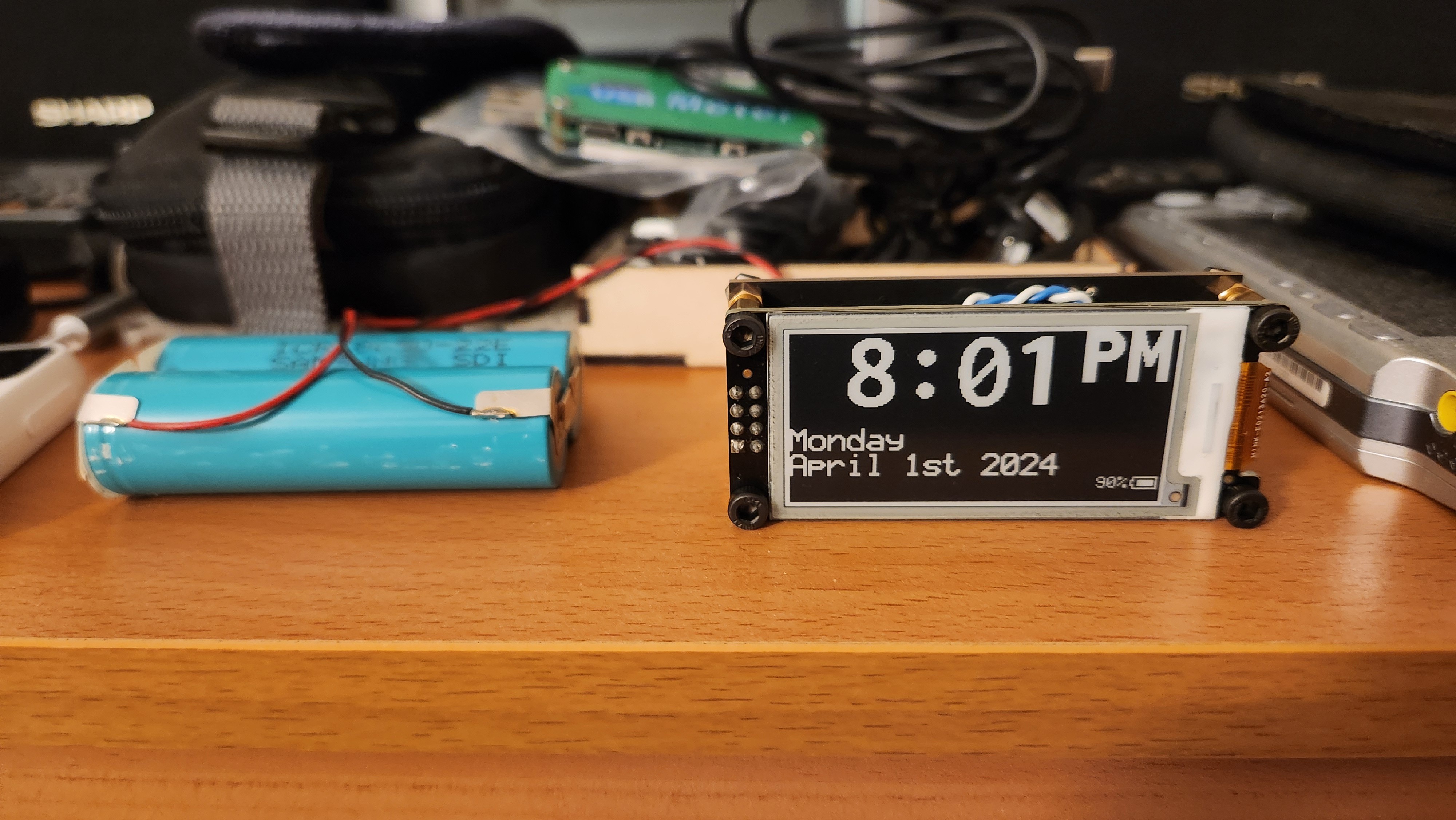
Making matters worse is that the display module I used while supposedly working off 5V or 3.3V only works downs to ~3.6V for me so as is, this clock cant use most of the available power from a lipo/li-ion battery. I will definitely implement mcu sleeping into my code though to drown the 9.5mA draw down to something around the 40uA range which should help quite a bit in the runtime department.
So the project isn't quite finished yet, but if you'd like to get the pcb (with fixed usb c connector pads of course) made or play around with the software just reach out to me via email (sjm4306@gmail.com) for the design files. I've put quite a bit of work into this project so going forward on projects like this I'll charge a token $5 for design files.
 sjm4306
Discussions
Become a Hackaday.io Member
Create an account to leave a comment. Already have an account? Log In.