 esben rossel
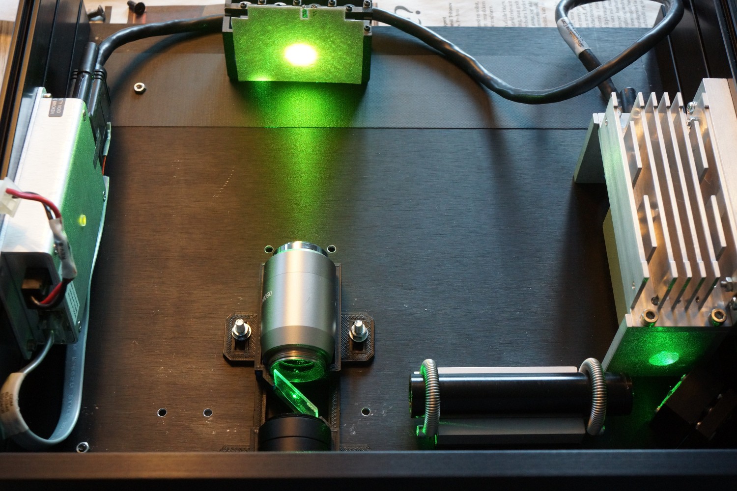
The Otter DIY Raman spectrometer inhabits two boxes:
- A box for the laser and the sample
- Another box for the spectrograph
Raman scattered radiation has an intensity of 10⁻⁷ compared to Raleigh scattered light and even less of the laser of course, so to avoid the CCD completely drowning in laser light, the two are kept separate.
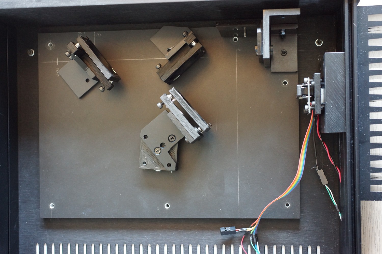
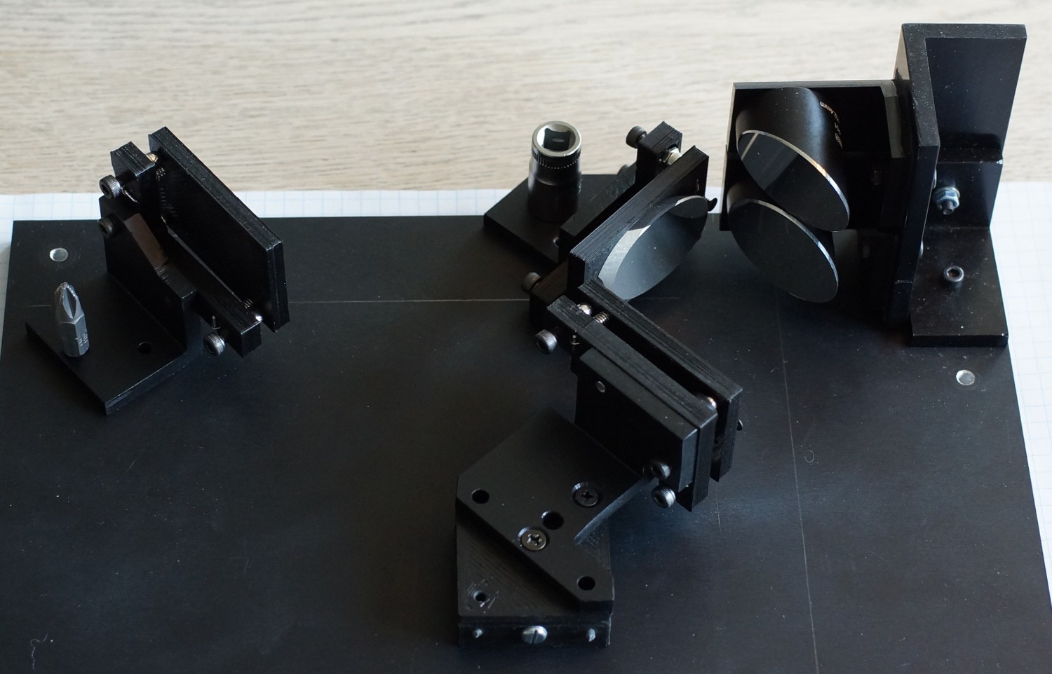
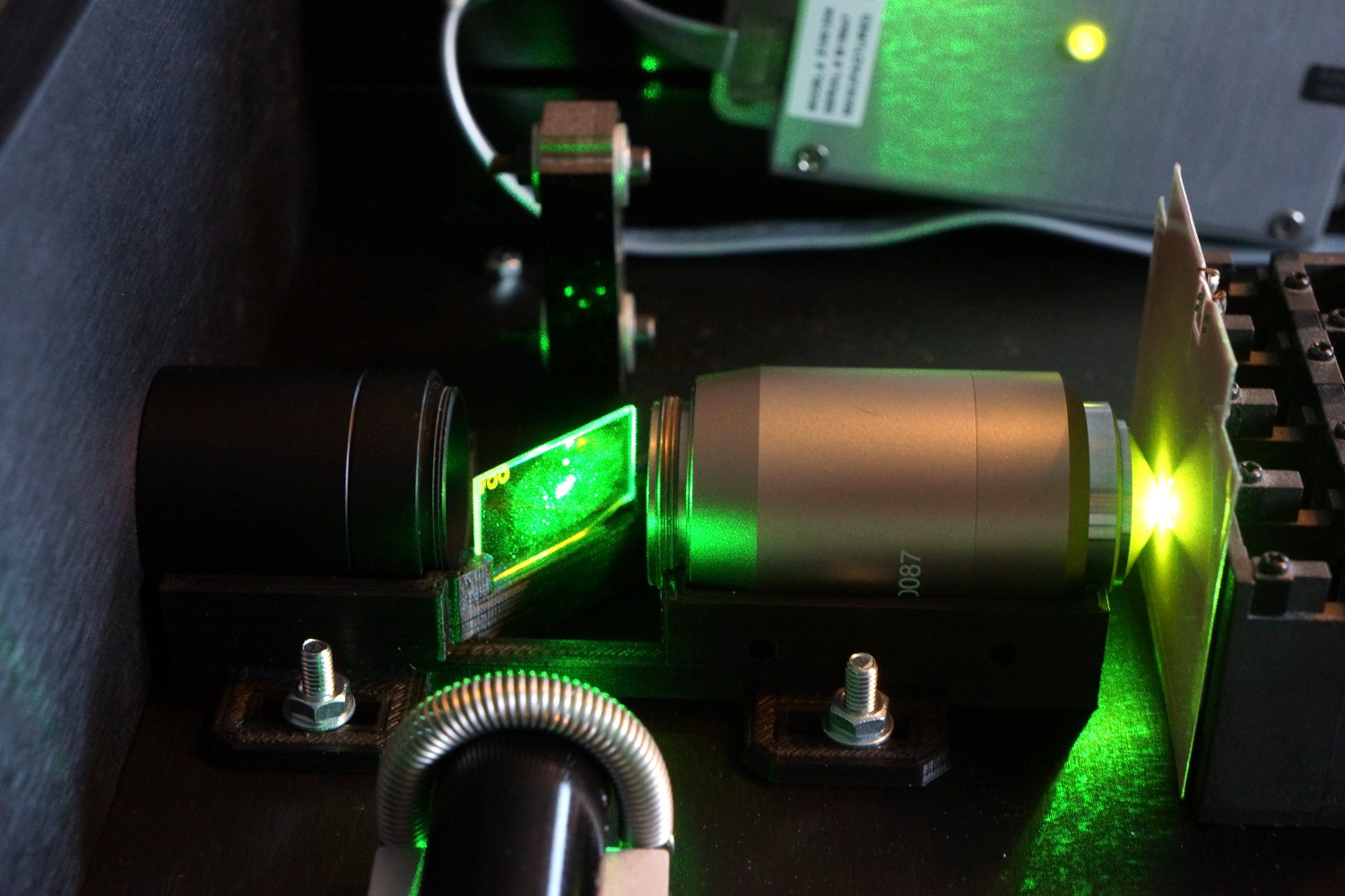
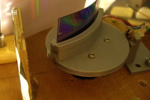
1. The Raman excitation setup
The Raman excitation and collection is the usual back-scattering setup, and the schematic looks like this:
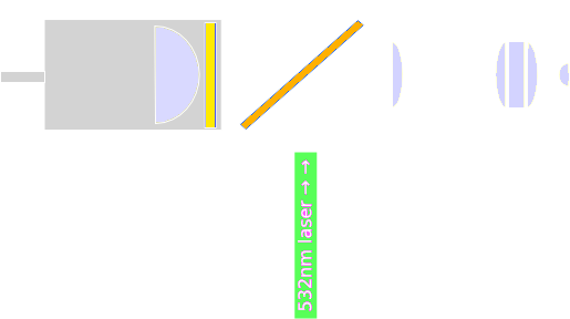
The laser is reflected off of the 540 nm dichroic long pass mirror. It's focused onto the sample by a microscope objective, which also serves to collect and collimate the scattered radiation. The long pass dichroic mirror and the 540 nm edge filter transmits the Stokes-shifted Raman radiation, while rejecting the Raleigh scattered light (and the anti-Stokes Raman signals). Finally the planoconvex lens focuses the Raman radiation onto an optic fiber going into the spectrograph.
This setup is more or less a copy of many commercial Raman probes, and almost identical to the one presented in Mohr's article (J. Chem. Educ., 2010, 87 (3), pp 326–330).
The diffracted light of interest is from 278-4000 cm⁻¹ in the Raman spectrum, which with an excitation wavelength of 532 nm translates to 540.0-675.6 nm, because:
2. The spectrograph
The spectrograph is a two off-axis parabolic mirror design proposed and analyzed by Gil and Simon (Appl. Optics, 1983, 22 (1), pp 152-158) and first realized by Schieffer et al. (Appl. Optics, 2007, 46 (16), pp 3095-3101). It came to my attention after reading T.J. Nelsons project page.
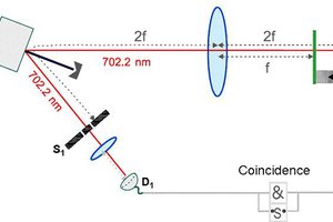
The spectrograph consists of two off-axis parabolic mirrors (OAP) positioned so their tangential planes are normal to the grating's dispersion plane, and aligned so their off-axis focal points coincide. It's hard to illustrate in 2D, so the diagram is broken into several pieces:
I apologize for the poor illustrations.
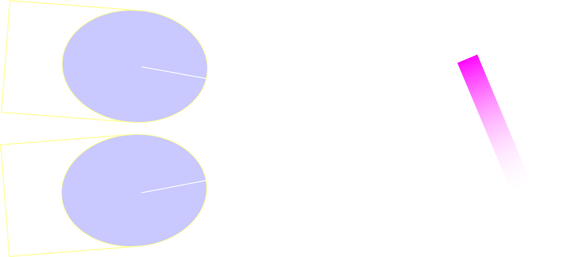
The OAPs and the diffraction grating. The angle 2α is equal to the angular dispersion of the central rays.
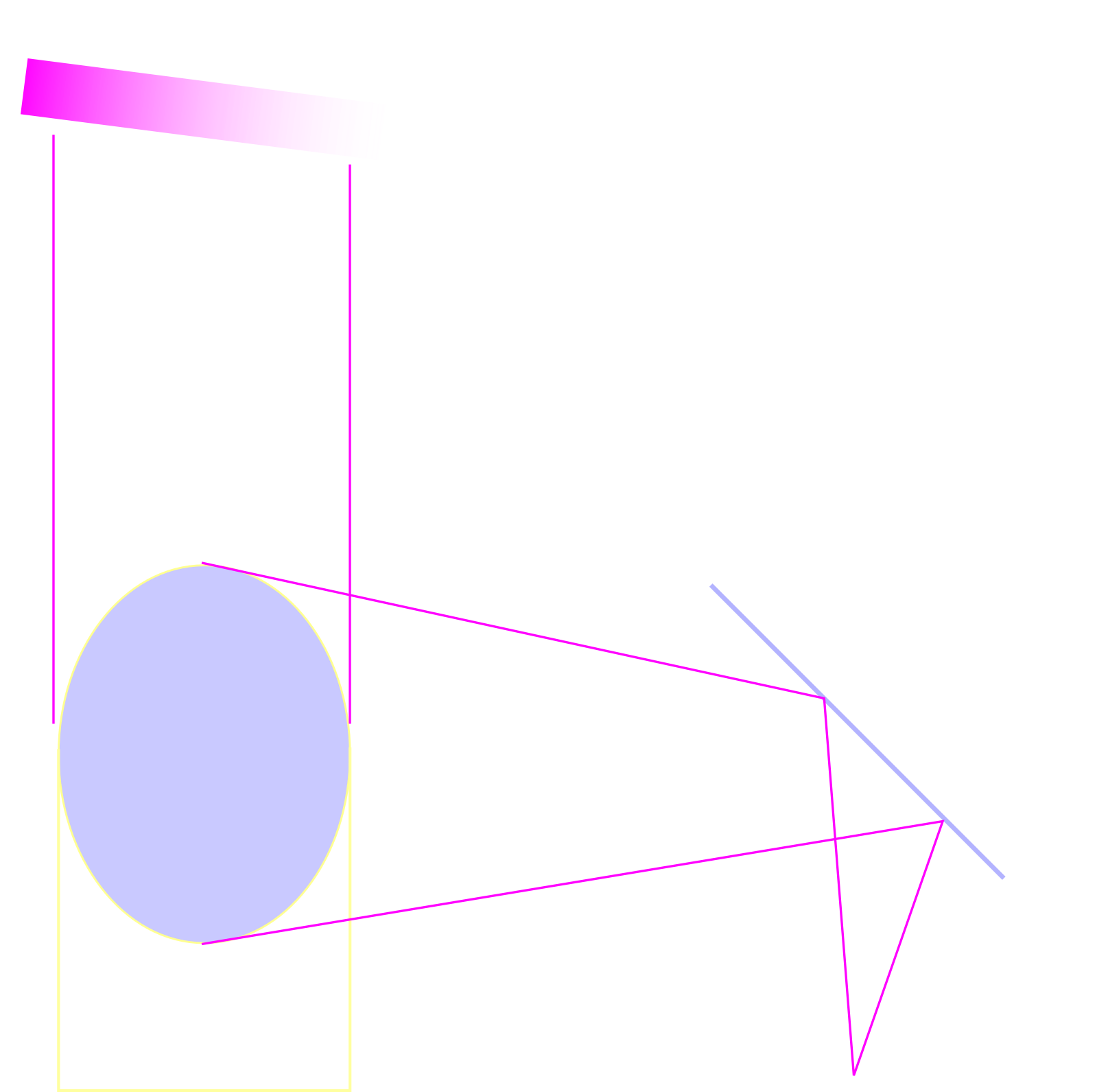
The light enters the spectrograph from an optic fiber and is collimated by the first off-axis parabolic mirror (OAP1) and sent to the diffraction grating.
The collimated light hits the diffraction grating, which disperses the light. Finally the second off-axis parabolic mirror (OAP2) focuses the diffracted light onto a linear CCD (TCD1304DG).
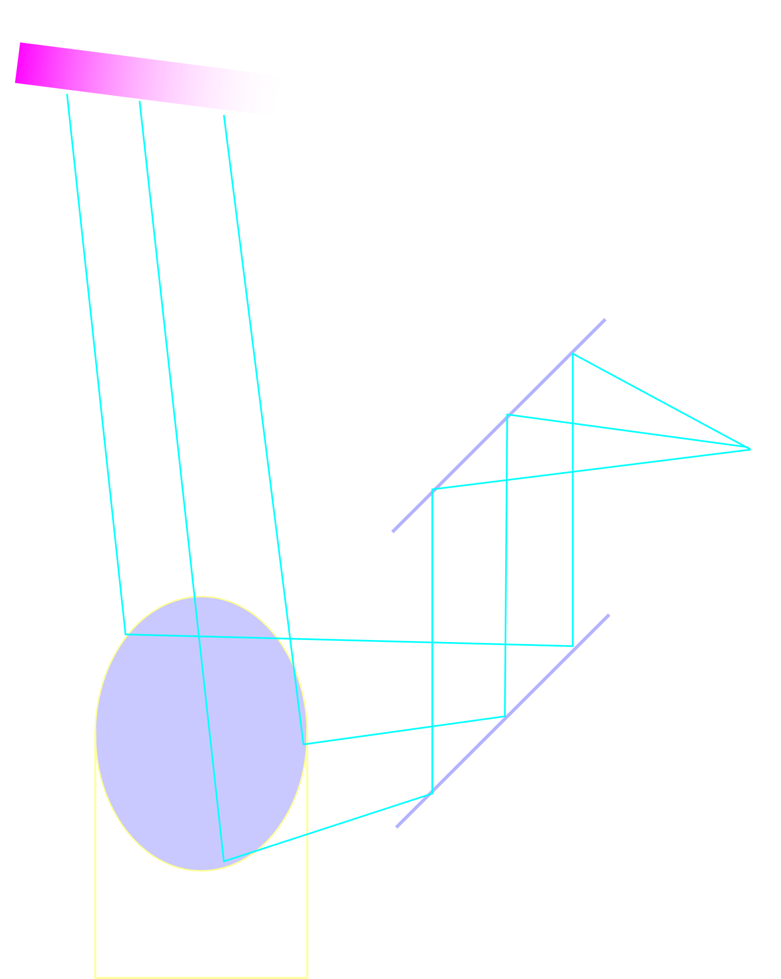
It's not super-clear from the diagram that the two OAPs are stacked over each other. Mirror 1 is employed for convenience, while the "folding" action by mirror 2 and 3 facilitates precise focusing by adjusting the length of the path of the diffracted light.
Here's a simple 3D-diagram, rendered with openscad and meshlab:

And the .stl file if you want to have a closer look.
As the both the diffraction and the CCD are all (ideally at least) positioned in the exact focal points of the off-axis parabolic mirrors, there's no spherical abberation, and because of stuff I don't understand coma, astigmatism and field curvature is minimized. My guess is the abberations introduced by OAP1 is cancelled by OAP2, which requires the two OAPs to have a common focal point, making this design different from the classical Czerny-Turner spectrograph.
In the 2007 paper by Stephanie L Schieffer an impressive resolving poweR of 2.5·10⁴ with a 10µm slit and 1500 l/mm grating is reported.


 andreas.betz
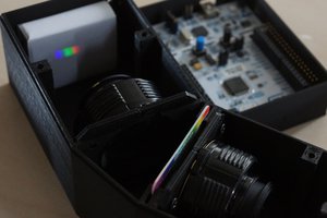
 fl@C@
fl@C@
I apologize if this has been asked/answered but apart from the camera.... what was your parts cost? Have you looked a graphene vs graphite using your instrument? That would be a very nice spectrum pair to look at. Thanks for sharing this. Doug