 kelvinA
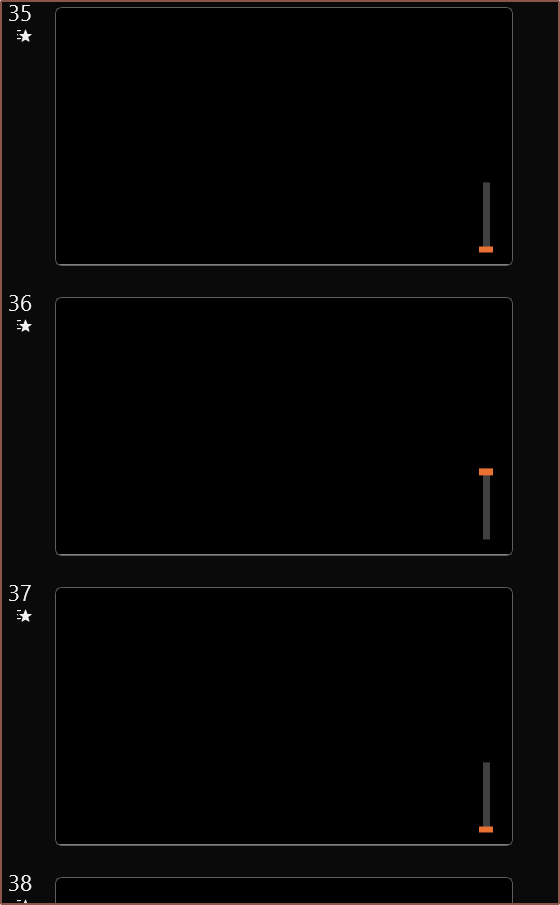 So I had the idea to actually create a simple PowerPoint animation where the orange bar would slide up and down 50mm with a smooth start/end transition to account for acceleration. Then, the time duration of both the animation and the transition to the next slide would be changed so that it looks like my finger is actually moving the slider. I found that a 0.12s animation and 0.14s slide transition achieved this without my finger doing any particular effort.
Then I finally used the SUVAT equations in the real world for once and I got an accel value of 13.89m/s^2. Since all these measurements are kind of rough, I stuck with 2 significant figures thoughout, thus I used 14m/s^2 for my calculations.
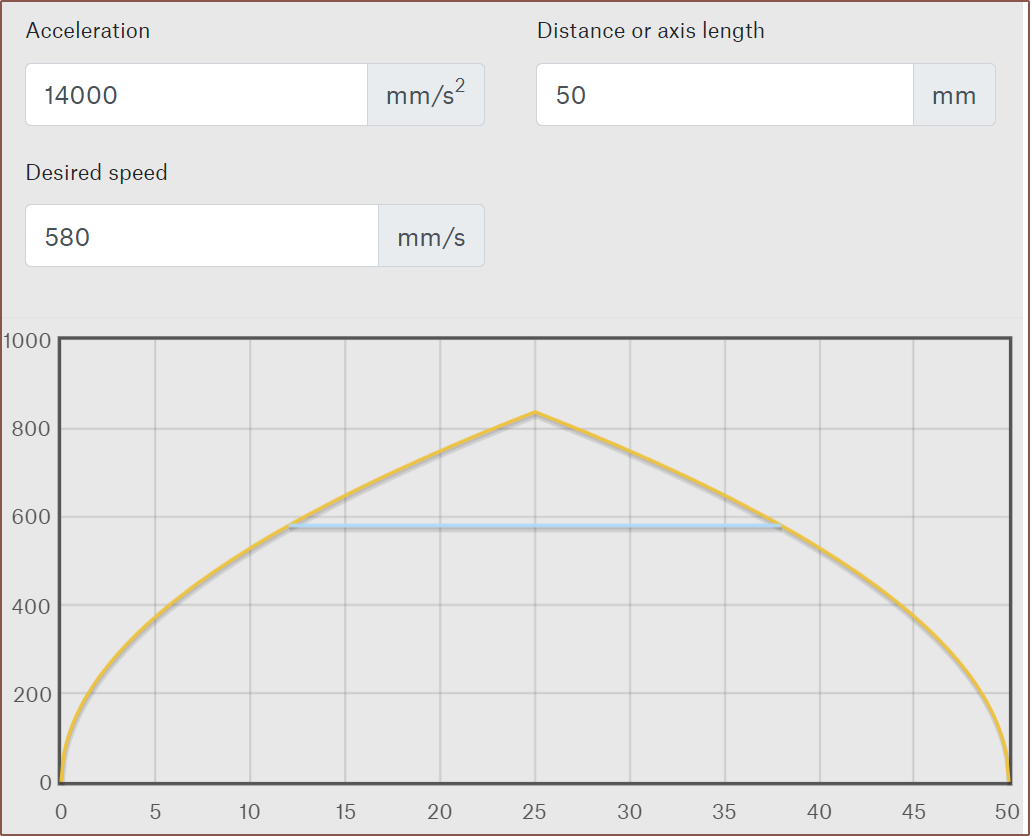
I then used Prusa's calculator to graph out the speed profile when doing the expected max typical movement of 24mm (each column in the Tetent layout is 6mm apart):
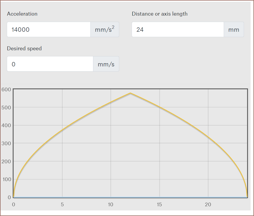
I confirmed that it was 580mm/s. If you're wondering, the peak finger movement from end-to-end was 833mm/s.
Dividing this by the circumference of the 16mm pulley, converting to RPM and then multiplying by the gear ratio and I got 5000RPM to 2sf.
This is a bit of a problem because I still need to be able to generate a virtual wall force at these speeds, such as if the finger starts to accelerate and then hits the virual wall halfway through the movement.
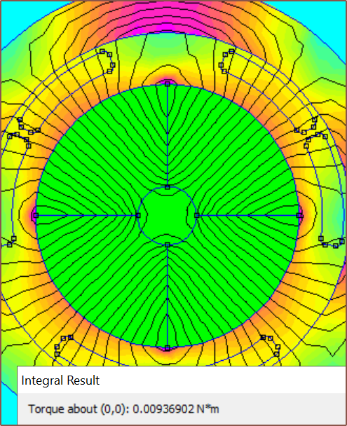
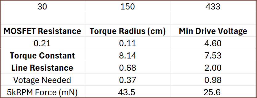
After spending a while deriving the correct equation, it's not looking good at 5KRPM:
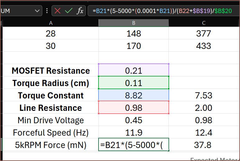

Understandably, negative values all coincide with all motors with a torque constant over 10. For example, I needed to go to the TBC1636-12V to get a non-negative force of 37.8mN and that configuration uses 44% more power than the 24V variant.
Finding the max turn count
10 > 13.77x / 38
380/13.77 > x
27.6 > x
Turns need to be 27 or less.
I did also consider just having a higher drive voltage that would sidestep all of this, such as running the motor at 9V, but that may complicate electrical matters (not like running a motor on the same 5V rail as logic circuitry is a smooth sailing idea either) since it would be nice to have everything fully contained on Tetoroidiv.
Actually, as I'm typing this, I'm checking motors to make sure everything is all correct, and it's not. For starters, a 1656 motor snuck into the data. Additionally, assuming 0 voltage drop on the 5V rail is likely inaccurate. All this happened way past when I usually go to sleep because, as they say, "I don't need sleep, I need solutions!"
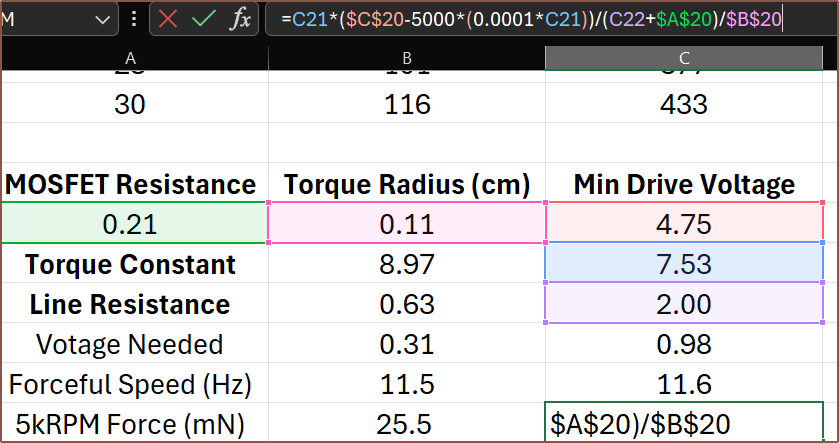
Anyway, 0.25mm wasn't going to make it, and since I can only have discrete coil heights, it meant that I started looking at the 0.3 / 0.35 / 0.4mm wire options. I was going to write this log talking about how power consumption has gone up 180mW just so that I could get a configuration that still had torque at 5kRPM, but I guess the sleep assisted because I've just tried a 0.35mm 21T option:
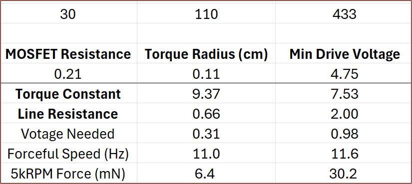
110mW is the all-time lowest power consumption I've witnessed. Considering my fingers would likely be in (what the enthusiast 3D printing group calls) "sensorless homing mode", 6.4mN should be enough to set a speed limit and decelerate my finger enough to reduce the EMF enough so that the motor can apply the full torque. I'm not going to risk it though and would rather use 20 turns; the max power goes up by 6mW but the max force on the belt goes to 25.5mN at 5kRPM.
I believe that a 580mm/s speed limit would probably go unnoticed:
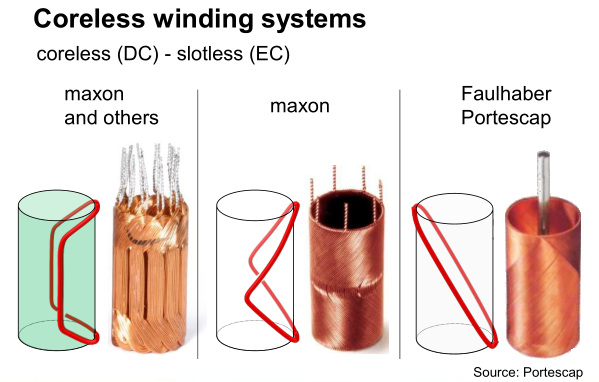
I checked all configurations of the brushed 1640 and none can provide torque at 5kRPM, meaning that the 1742 is the only brushed option at the moment. Currently, none of the commercial options are even close to the custom-designed solution, with the explanation for the BLDC options likely being because they only have a single pole pair.

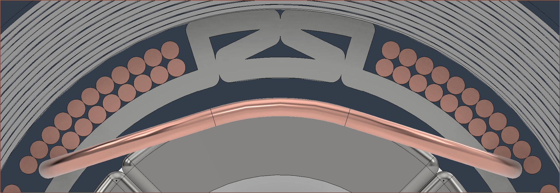
Another explanation is because these motors are usually made with windings such that they're self supporting, but it means that the wires themselves usually don't run perpendicular to the movement of the permanent magnetic field thus only a component of the total actually creates torque:
It's still more likely to be the pole pairs though. For example, if the TBC1636 had 2pp instead of 1, the power consumption would theoretically be 108mW.
[May 21]
I found out that the simulation is somewhat unreliable, in that changing the spacing between coils by tiny amounts would affect the torque integration substantially. For example, I'd get 6.76, 7.37 and 5.3 for 3.8mm, 3.6mm and 3.4mm respectively. It did seem though that values typically decreased on either side of 3.6mm.
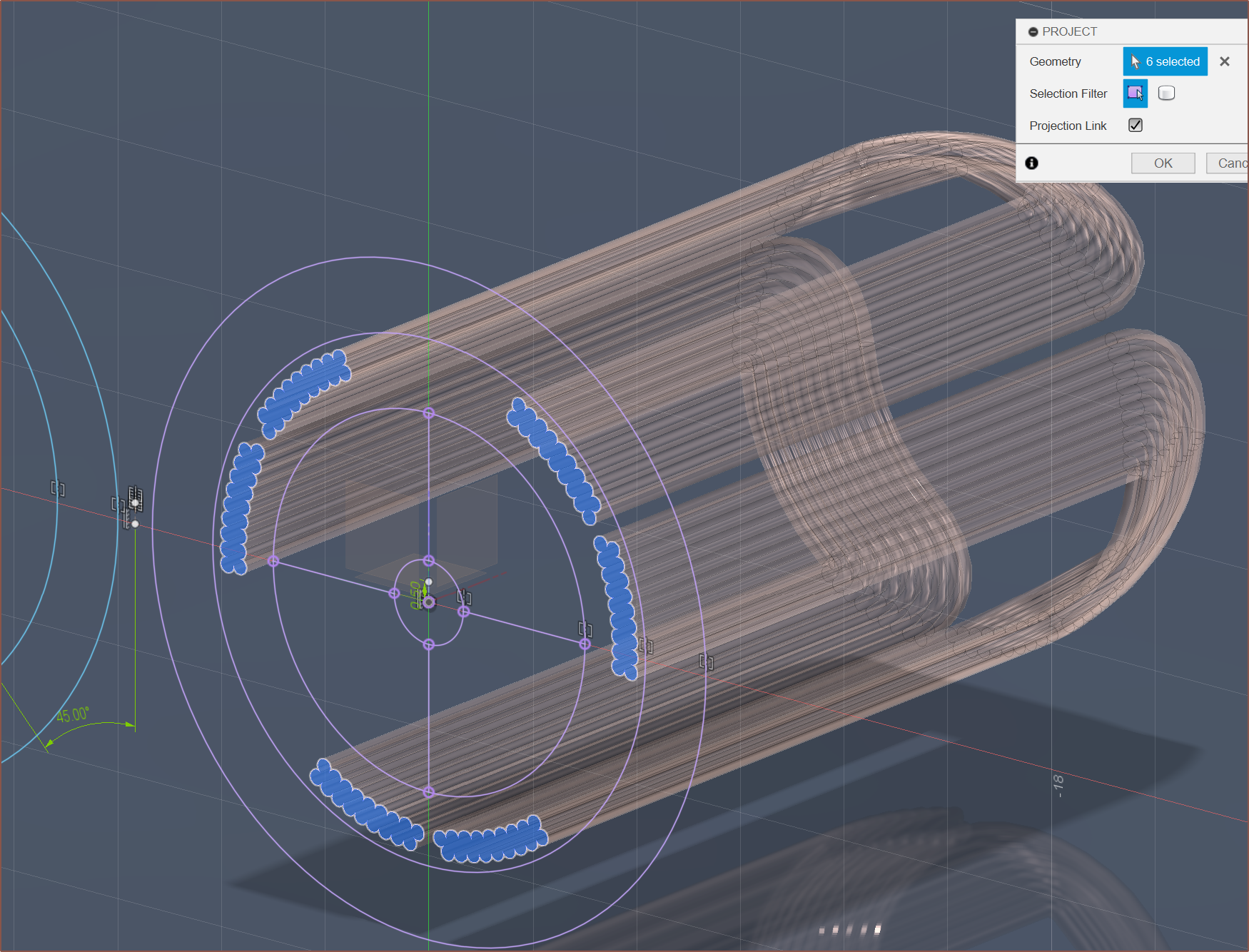
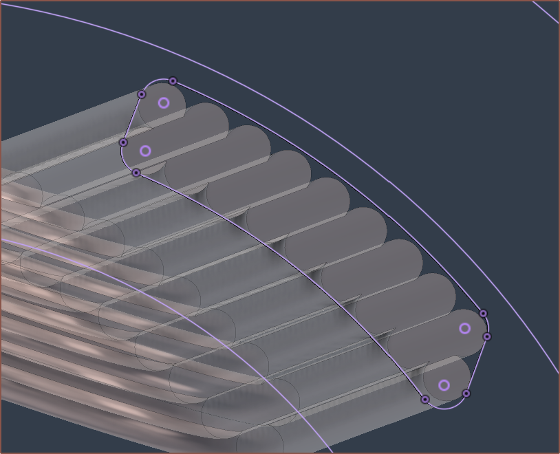
I tried things like modelling with a more accurate CSA (see below), and got 9.7 for 19 turns but 2.3 for 18 turns, so there was certainly something mysterious going on.
So then I tried an ultra-simplified CSA, where I got 6.8 and 4.9 for 3.6mm and 3.61mm respectively. The stars aligned when I used
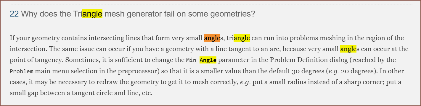
I looked into my problem settings and started tweaking values to see if anything made a difference, and min angle certainly did:
So I looked it up and this is what I found:
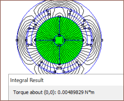
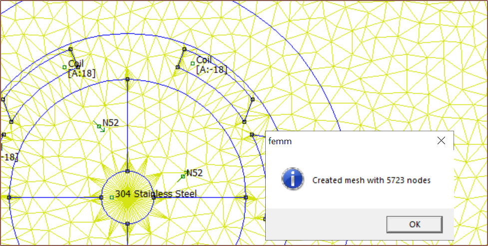
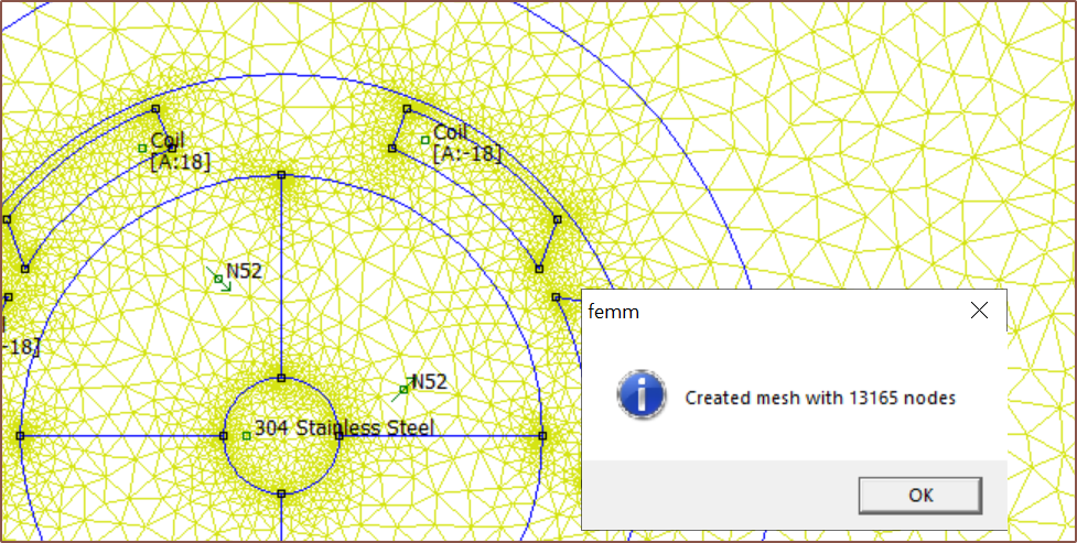
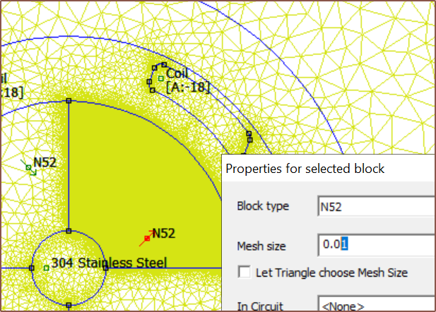
Thus, I went back to a rounded-edge CSA and started trying out different mesh settings for the air (inside the motor) and yoke, and I found that a mesh size of under 0.1 gave results that were reliable enough (+/- 0.1 torque constant).
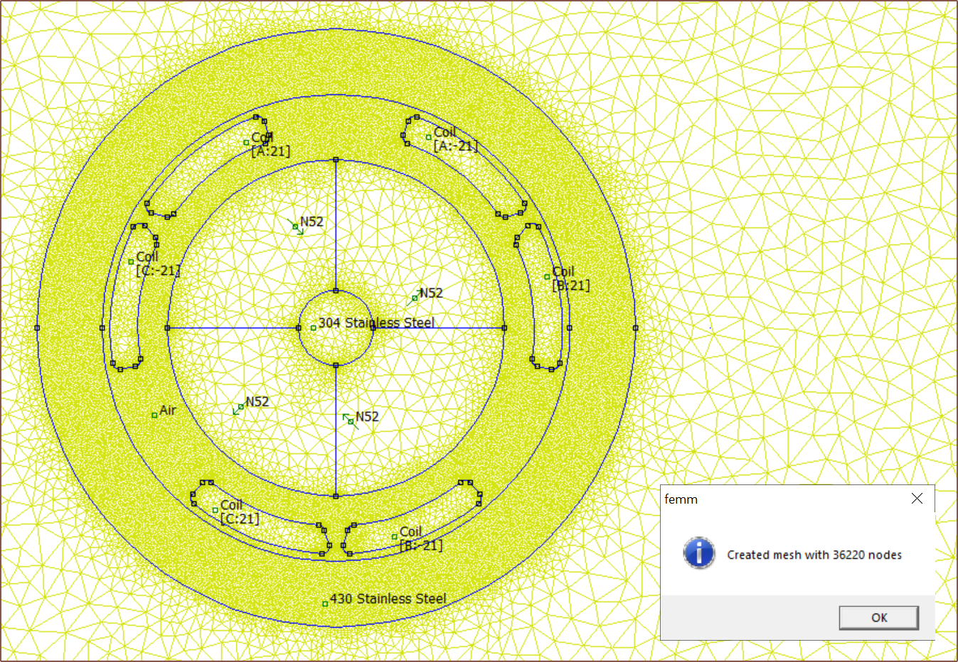
I also learned that I didn't have to generate the mesh before solving, as FEMM does that automatically. That means that I don't have to deal with the performance penalty of displaying so many nodes. Alternatively, I could always toggle "Mesh -> Show Mesh" in the top bar.
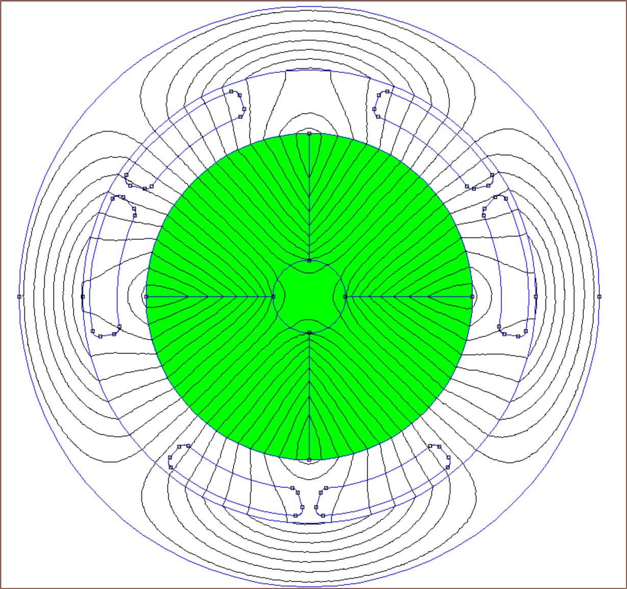
The solve takes maybe an extra 5 seconds but the flux lines look much smoother and, as mentioned before, the result is more stable.
Discussions
Become a Hackaday.io Member
Create an account to leave a comment. Already have an account? Log In.