Arnov Sharma
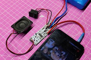
VIDEO-
DESIGN
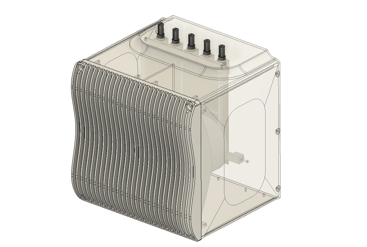
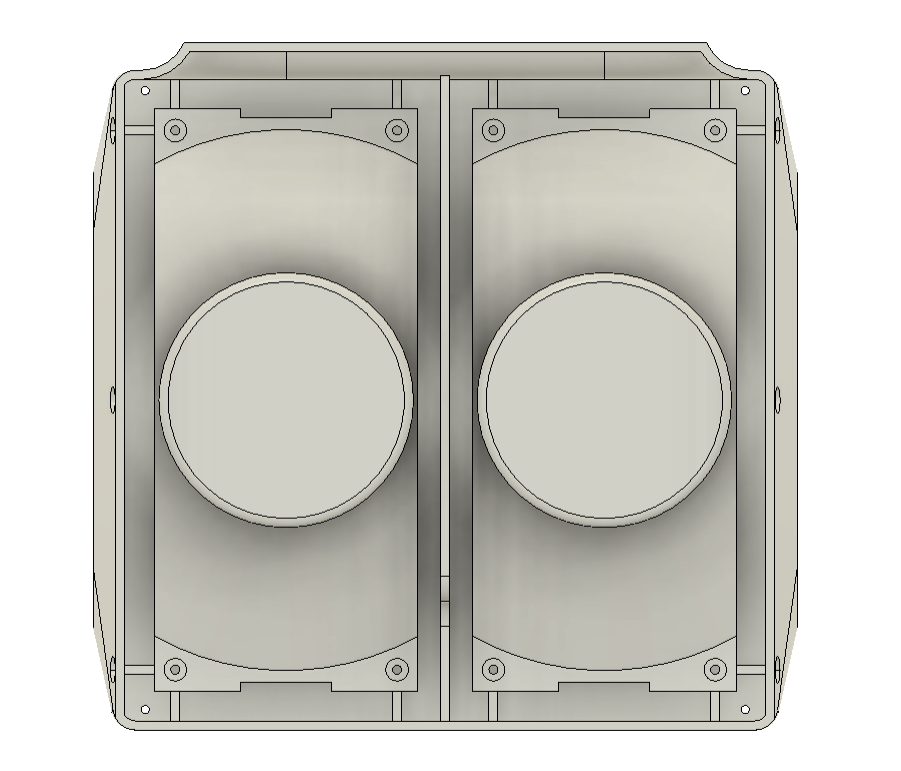
Here is the simple design I came up with. The entire body is designed in the shape of a cube, and the front has a speaker grill created of splines.
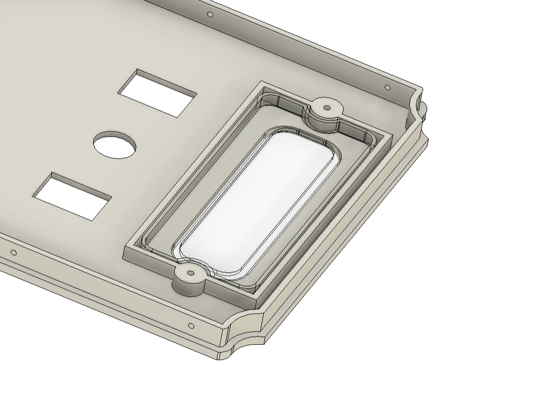
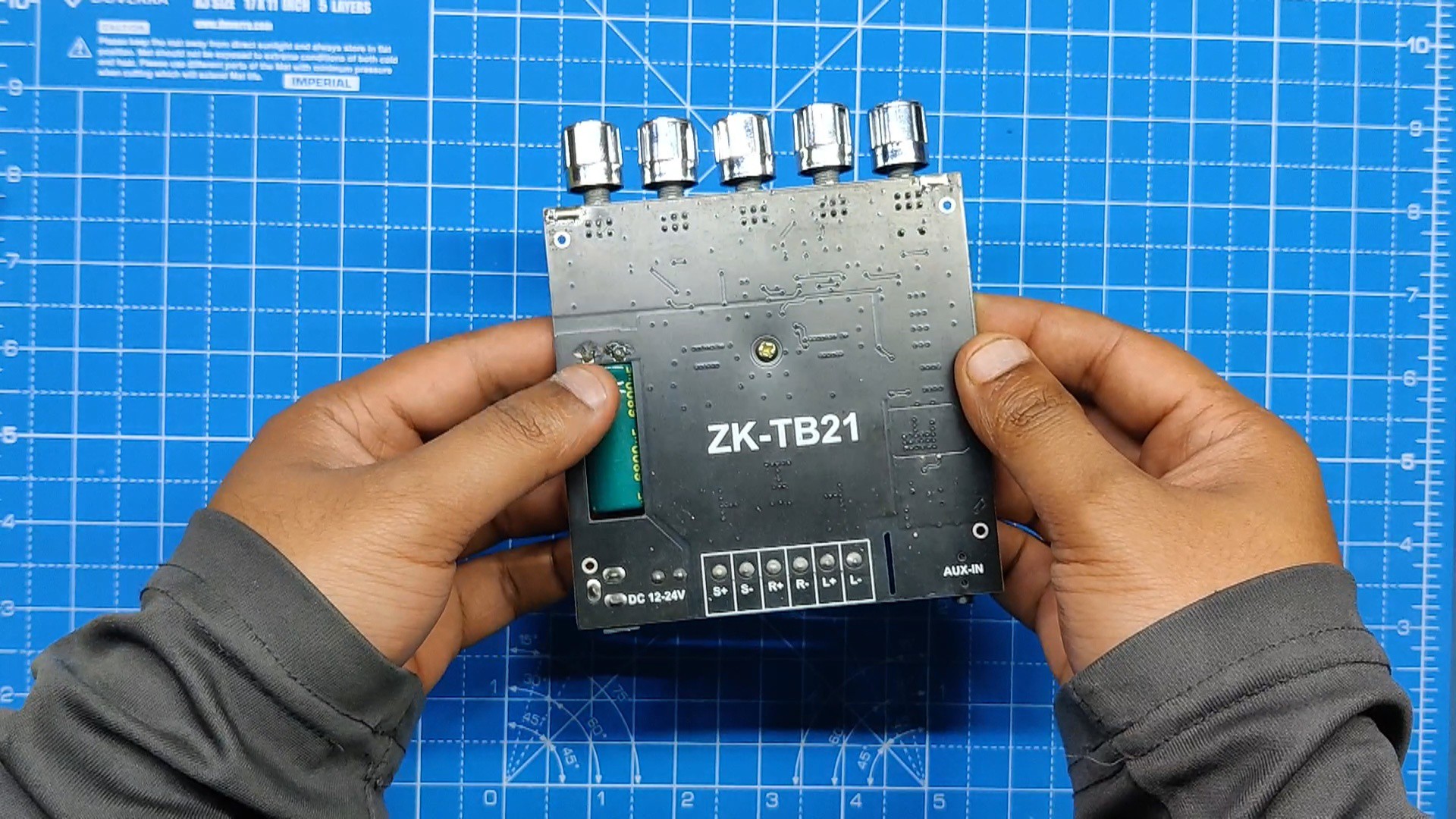
Control knobs for the Audio Module were positioned on the top face, and an RGB LED diffuser that lights up the background is located on the rear side of the speaker.
Additionally, there are two rocker switches on the bottom side that control the power supply for the speakers and the RGB light. A DC Jack is located on the back of the device to charge the battery.
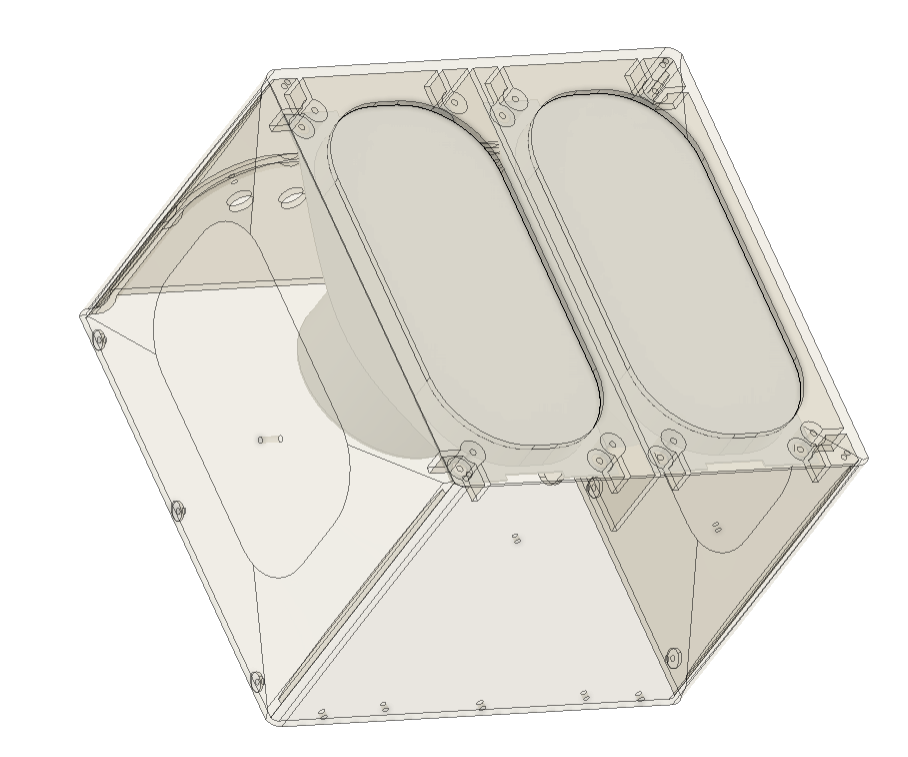
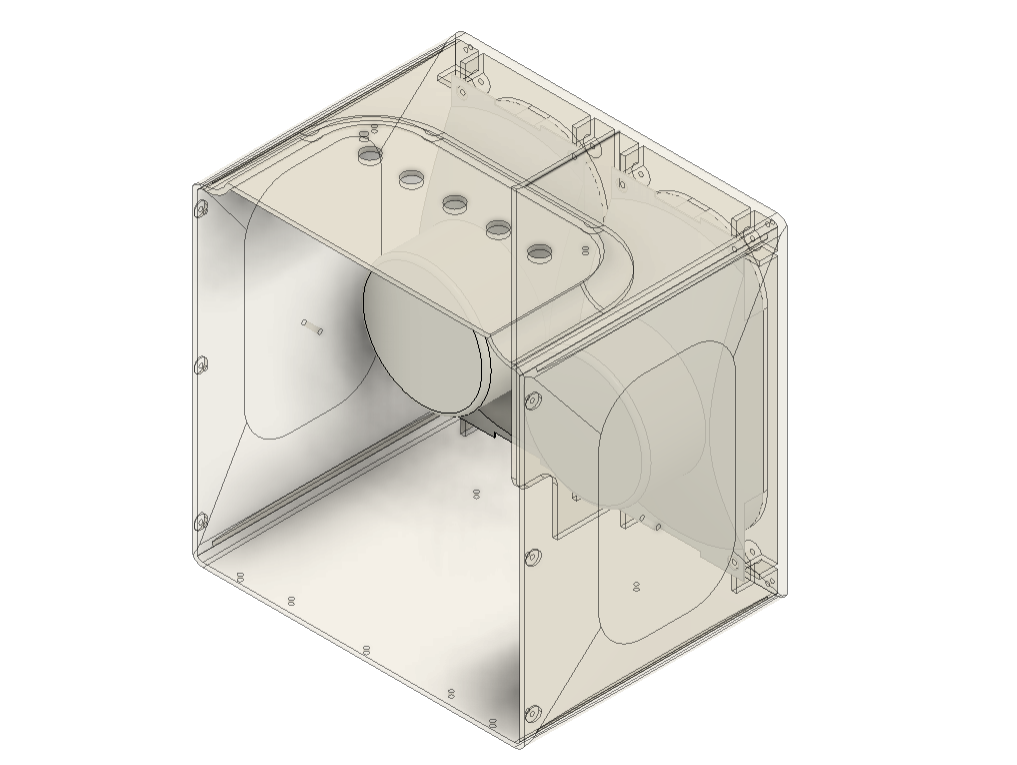
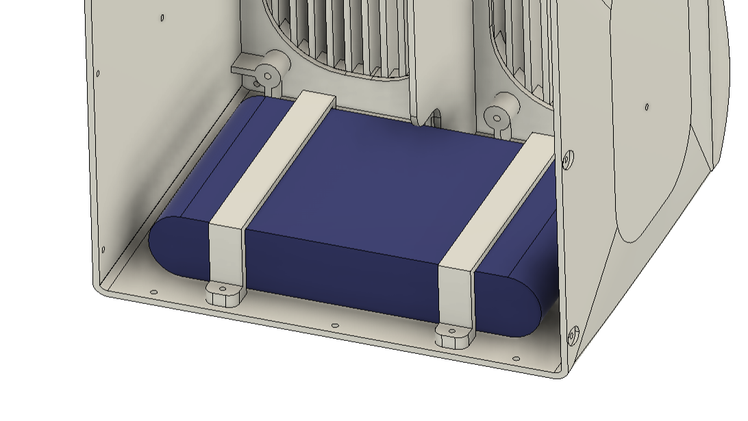
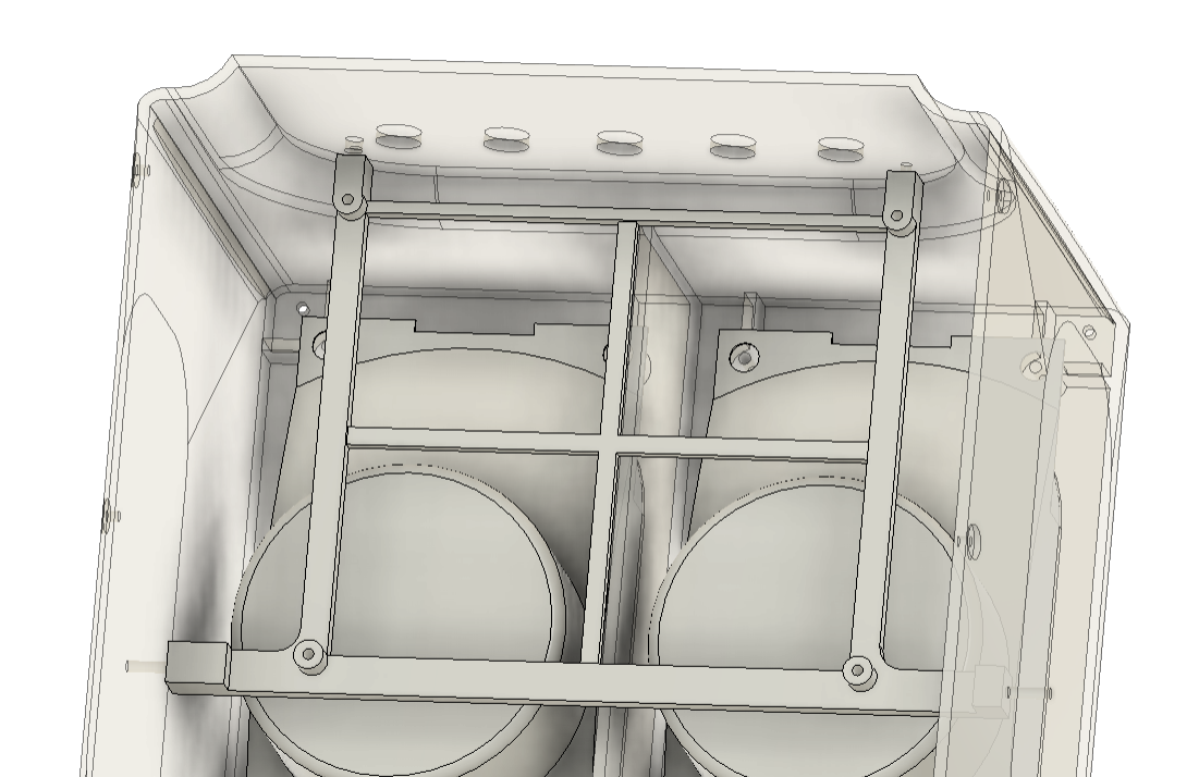
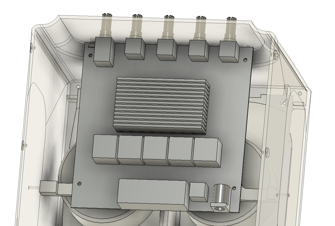
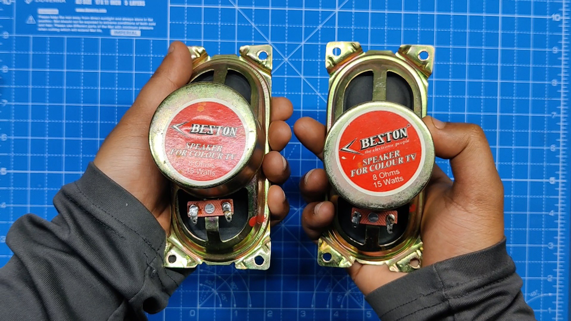
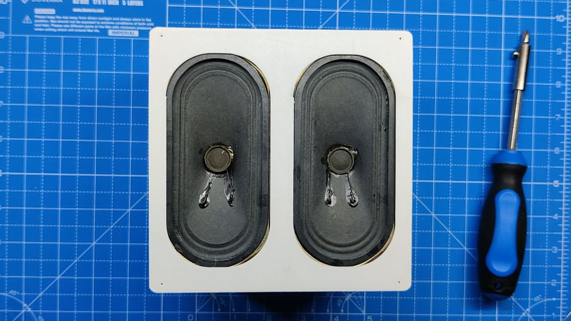
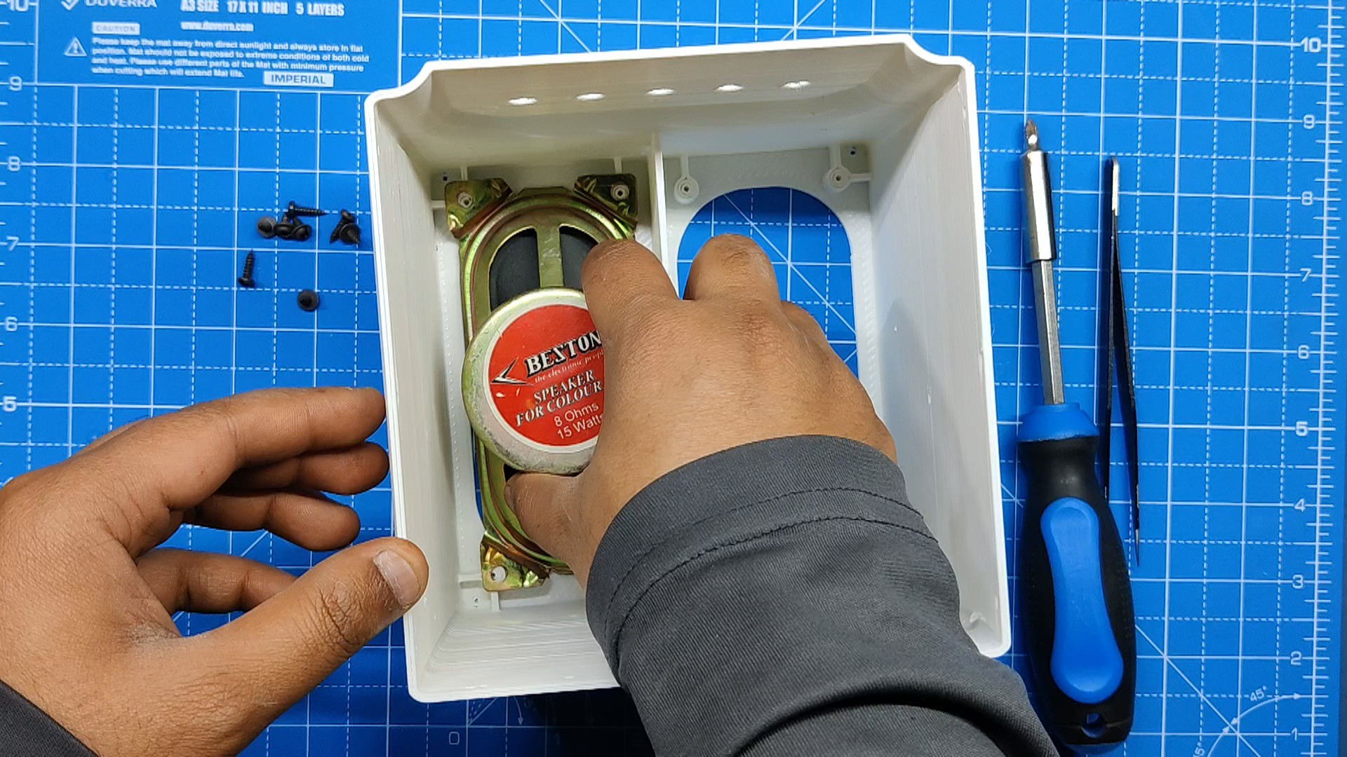
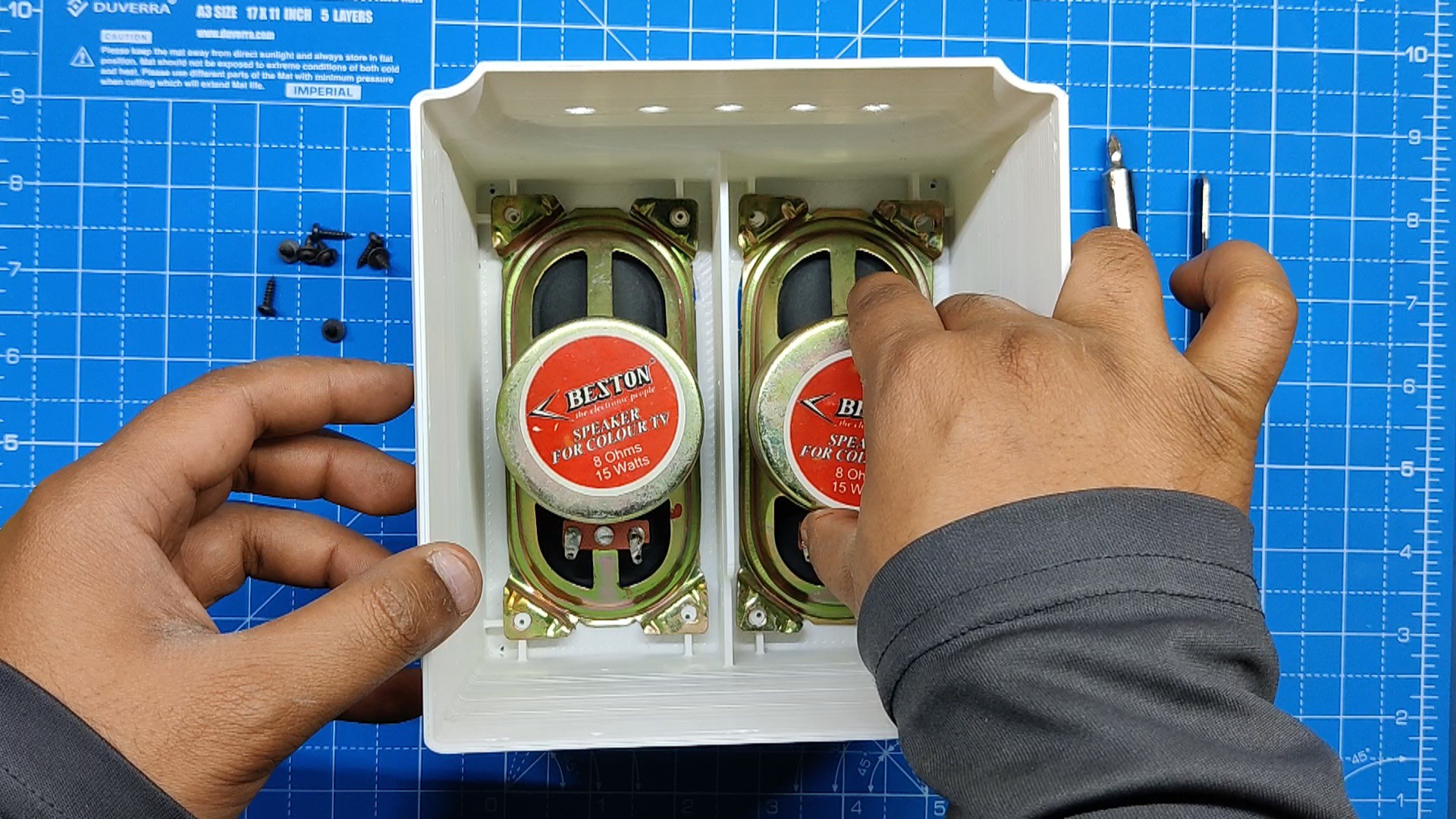
Regarding the internals, we put the two speakers we used on the interior of the front face of the project.
The speaker grill was modeled to fit on the front face using four M3 screws situated at each corner.
We have created a holder element that is first secured to the mounting holes on the audio module, and then the entire assembly is fixed within the base to keep it in place.
After exporting each component into an STL file, they were all 3D printed using white PLA and golden yellow PLA with a 0.2mm layer height and a 1mm nozzle.
PCB Design

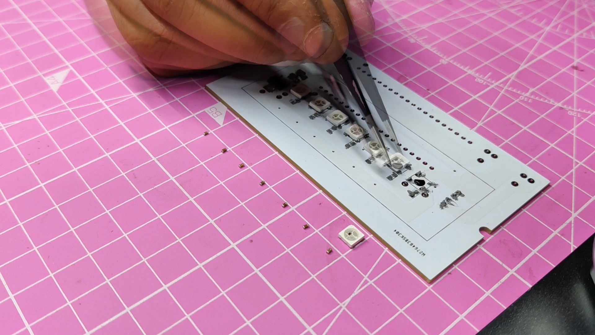
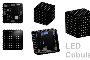
The PCB Design of this project's RGB Board was super simple as it only contains an array of WS2812B RGB LEDs connected in parallel with an Raspberry Pi Pico.
Schematic was made in total three sections which were the AMS1117 and battery section, the Raspberry Pi Pico Setup and the WS2812B LEDs array.
We needed to add an AMS1117 Voltage regulator configuration in order for the Raspberry Pi Pico and LEDs to function because we were utilizing a 12V Li-ion battery as our power source. This arrangement steps down the 12V of the battery to a steady 3.3V.
Two capacitors are connected to the input and output terminals of the AMS1117 in the simplest configuration. A 10uF 1206 capacitor is attached to the input side, while a 1uF 1206 capacitor is linked to the output side. Additionally, an M7 Diode and a switch have been placed between the input con2 terminal and the ams1117. A DC jack will be added using the CON2 to charge the 12V battery.
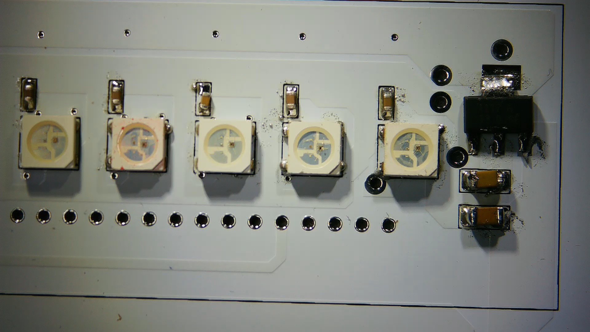
Each RGB LED was connected to a 100 nF capacitor for decoupling of the supply line.
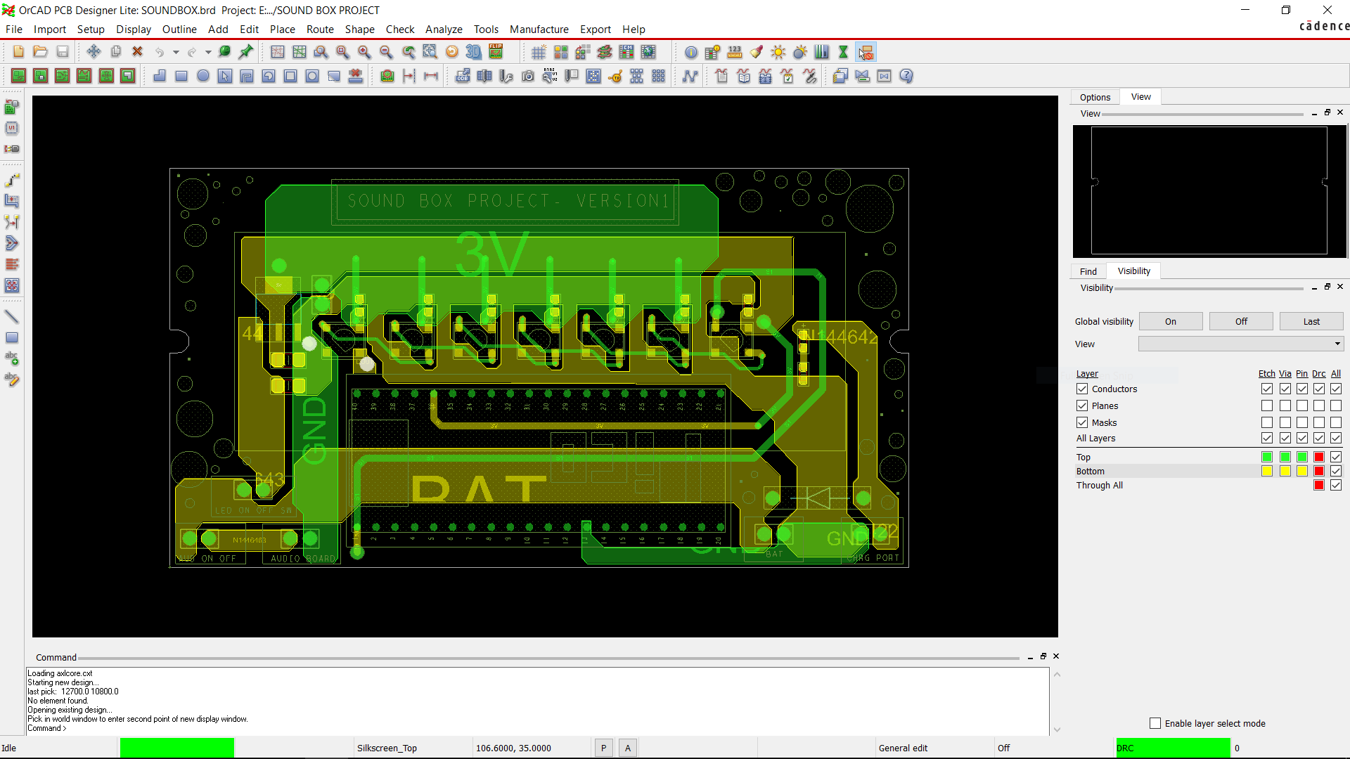
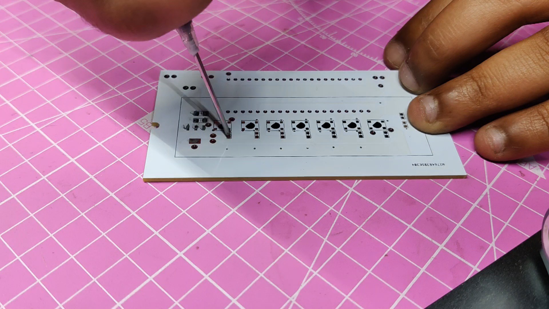
Following the creation of the schematic, we create the PCB design and layout the components on the board, based on the PCB model created in Fusion 360.
All of the SMD components, RGB LEDs, and the AMS1117 setup were mounted on the bottom. On the top side of the PCB were Pico and additional THT components.
PCBWAY Service
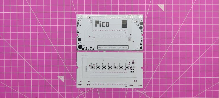
PCBWAY provided the PCBs for this project; we uploaded the Gerber data to their PCB Quote page and placed an order for white solder masks with black silkscreen.
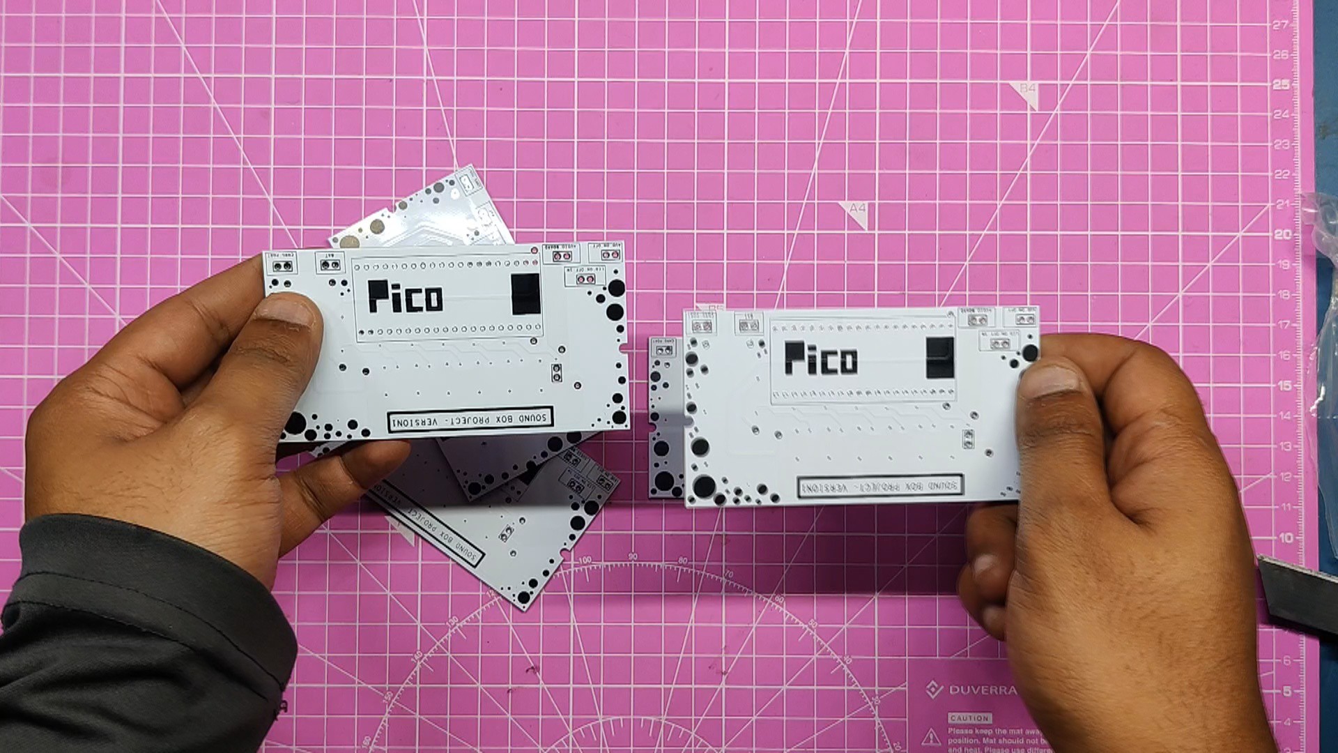
We received the PCBs in less than a week, which was extremely fast, and the quality was excellent as usual.
I've been using their service for a while now, and it's always excellent.
Check out PCBWAY for great PCB service at a low cost.
 Jack Flynn
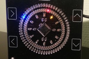
 Armin
Armin
 Kenneth Marut