 Arnov Sharma
VIDEO-
DESIGN


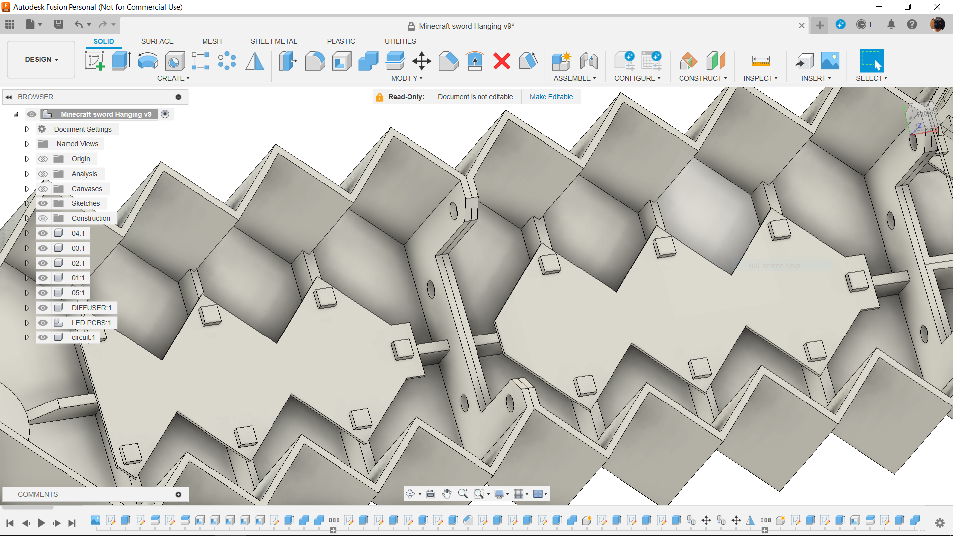
First, we load the image of the Minecraft sword into Fusion360 and set its dimensions to 550 x 280 mm.
Next, we modeled the sword by tracing its outline, and we then extruded the sword with a thickness of 60mm.
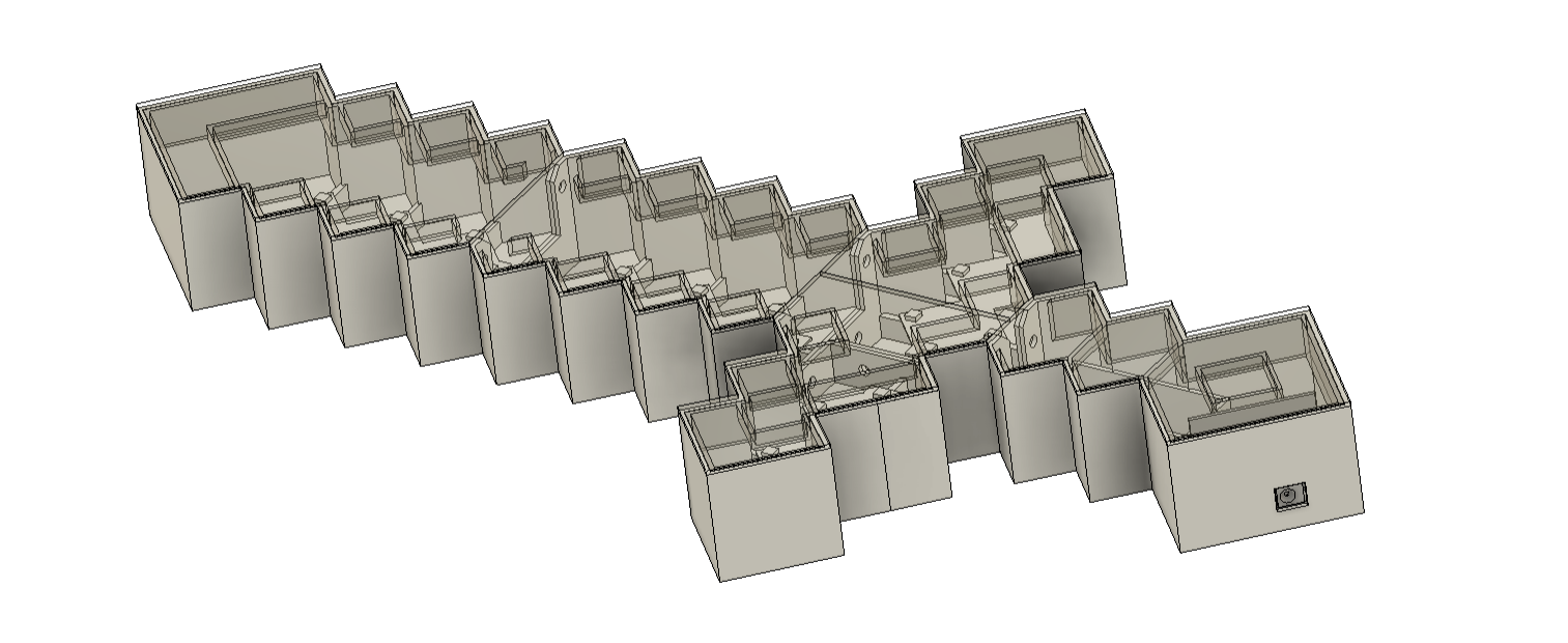
Using the shell command, we hollow out the entire model and then divide it into five sections.
Later, we further divide each section into two parts, which are the lid and the lower base part, which will house the LED board.
We constructed an inner wall inside the lid part so that both parts can be pushed fit together, allowing the lid to fit over the lower half without the need for glue or screws.
We designed parts such that we could mount two sections together with M3 bolts and nuts in order to join several parts together.
The LED board inside the cross guard and blade portion of the sword illuminates the PLA-printed top lid part.
The circuit is housed in the grip portion of the model.
After the model was ready, we exported each of the five lower and five lid components into an STL file, then we used marble PLA for the lower part and transparent PLA for the lid to 3D print all of them.
PCB DESIGN
The main circuit board and the LED board were the two PCBs that we had to model in total for the PCB design.
Let us explore the LED Board first.
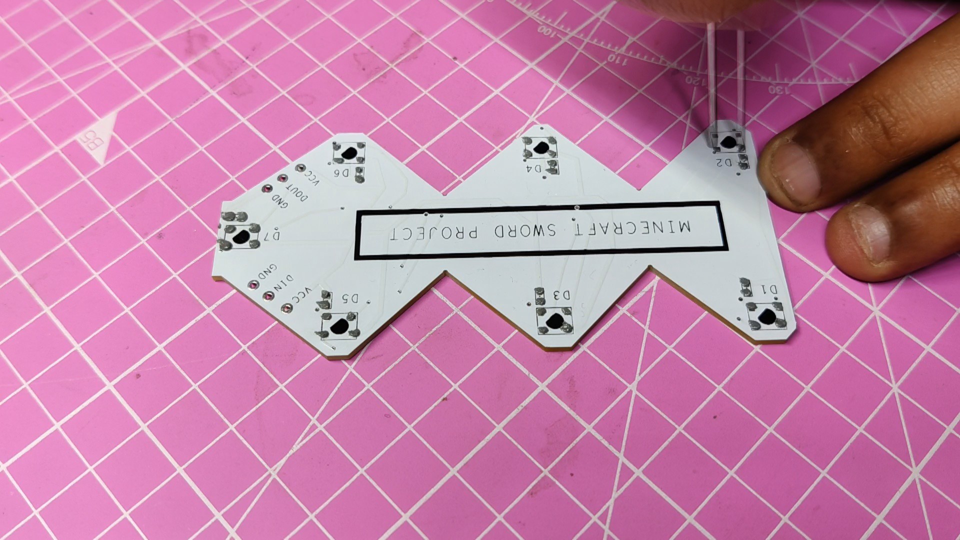
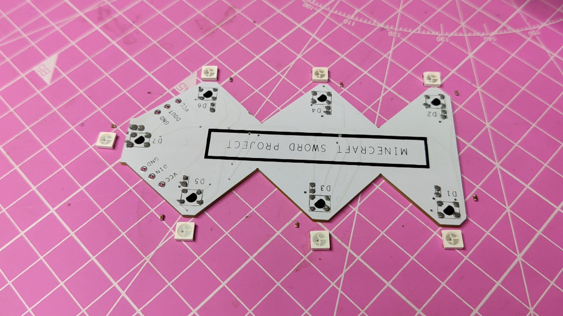
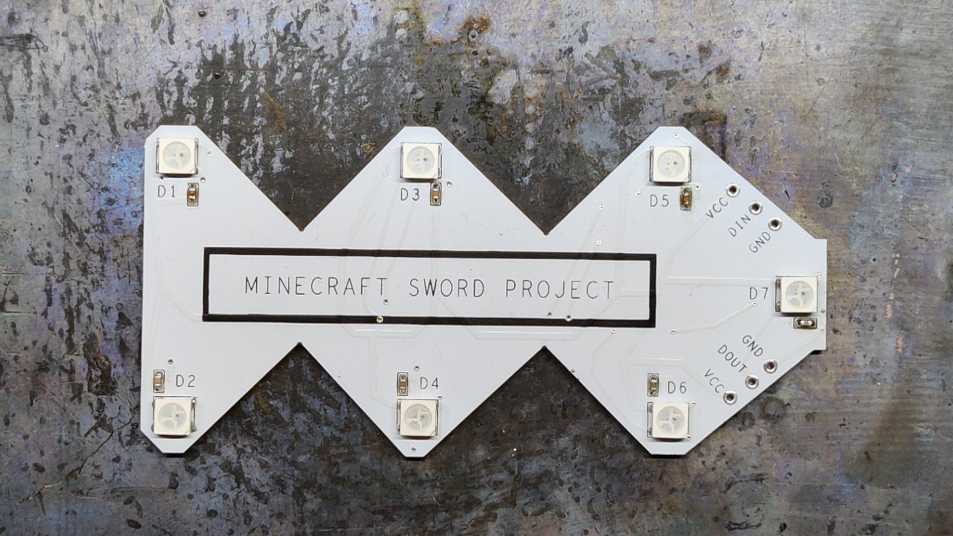
The LED Board schematic shows seven WS2812B LEDs linked in parallel, which are intended for lighting the sword's top lid.
The led board was designed so that we could create a single design and use it for every part, eliminating the need to create a distinctive LED board for each one.
Two sides have been added to the schematic: the input side and the output side. The VCC and GND of both sides are connected in parallel. The only pins that are different are the DIN and DOUT pins, which are each connected to a different CON2 pad.
To stabilize the LED, we use 100nF capacitors, each connected to a single LED, so a total seven capacitors were used.
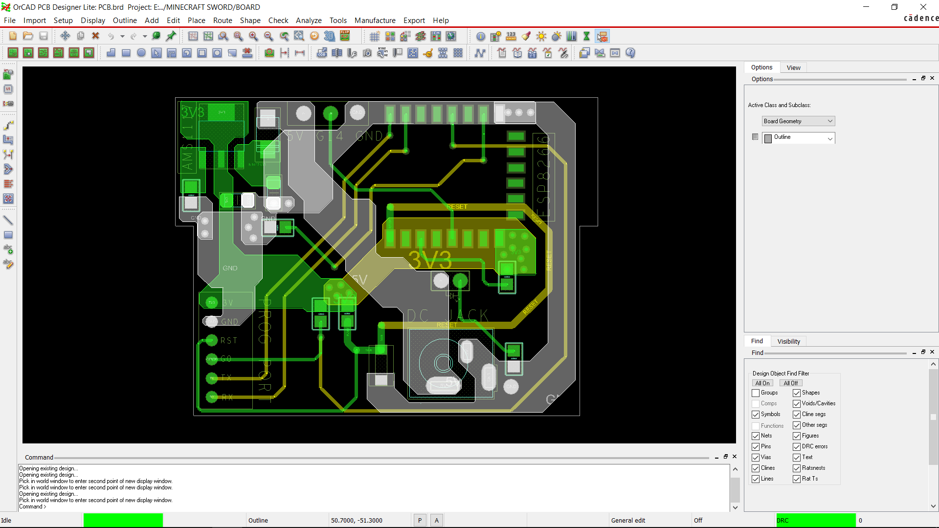
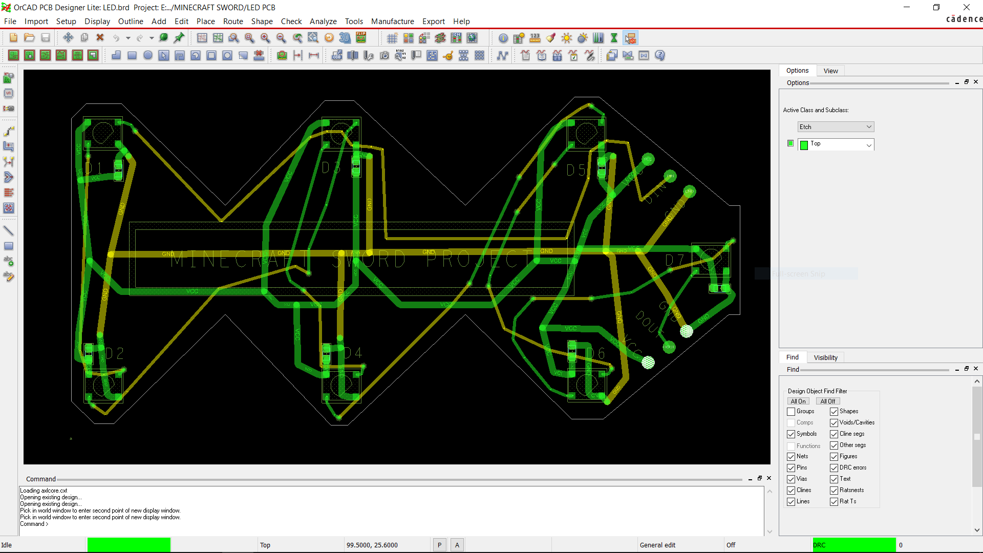
The PCB outline is created using model dimensions that are extracted from the Fusion360 model into a DWG file, which is then imported into our PCB Cad software.
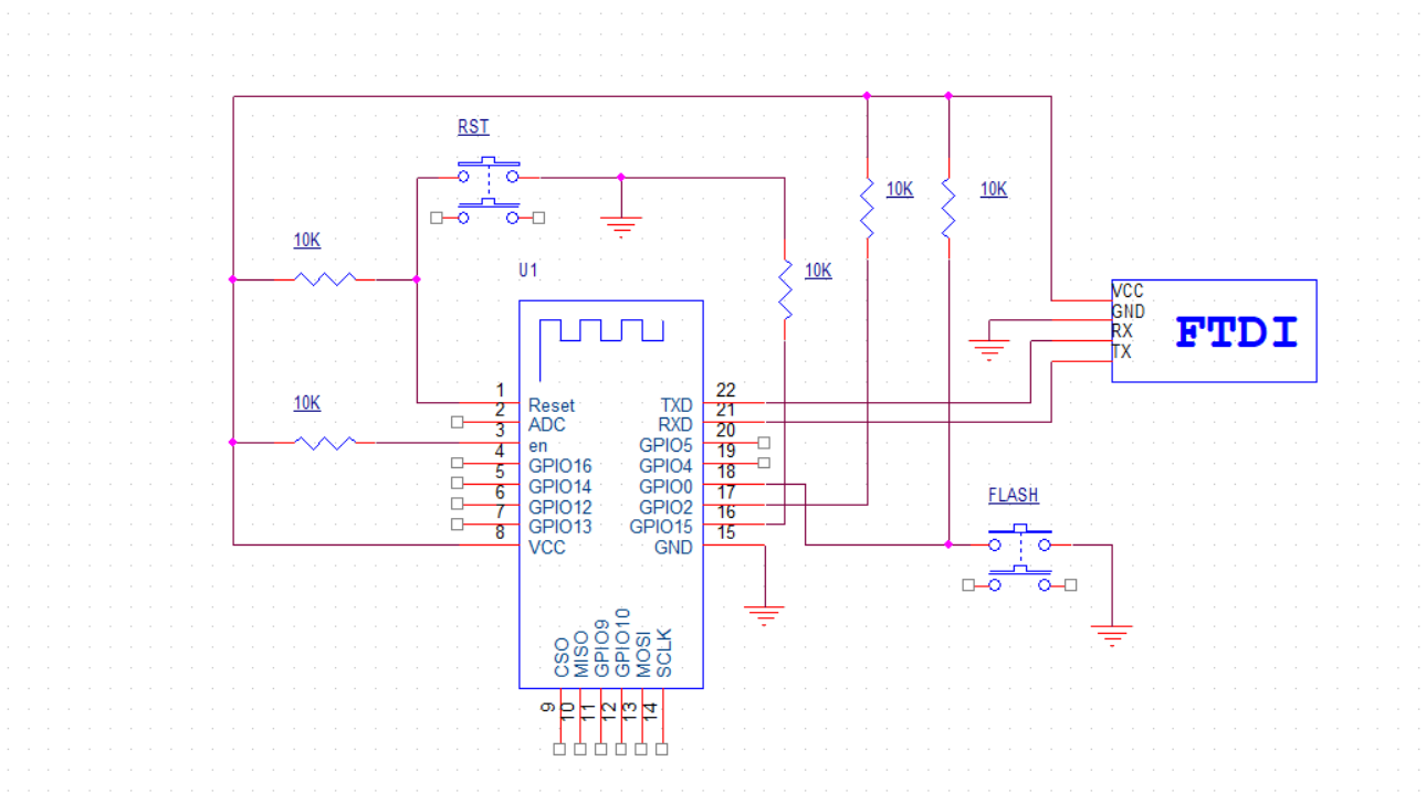
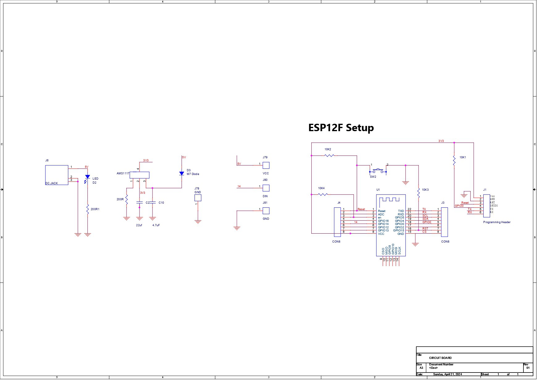
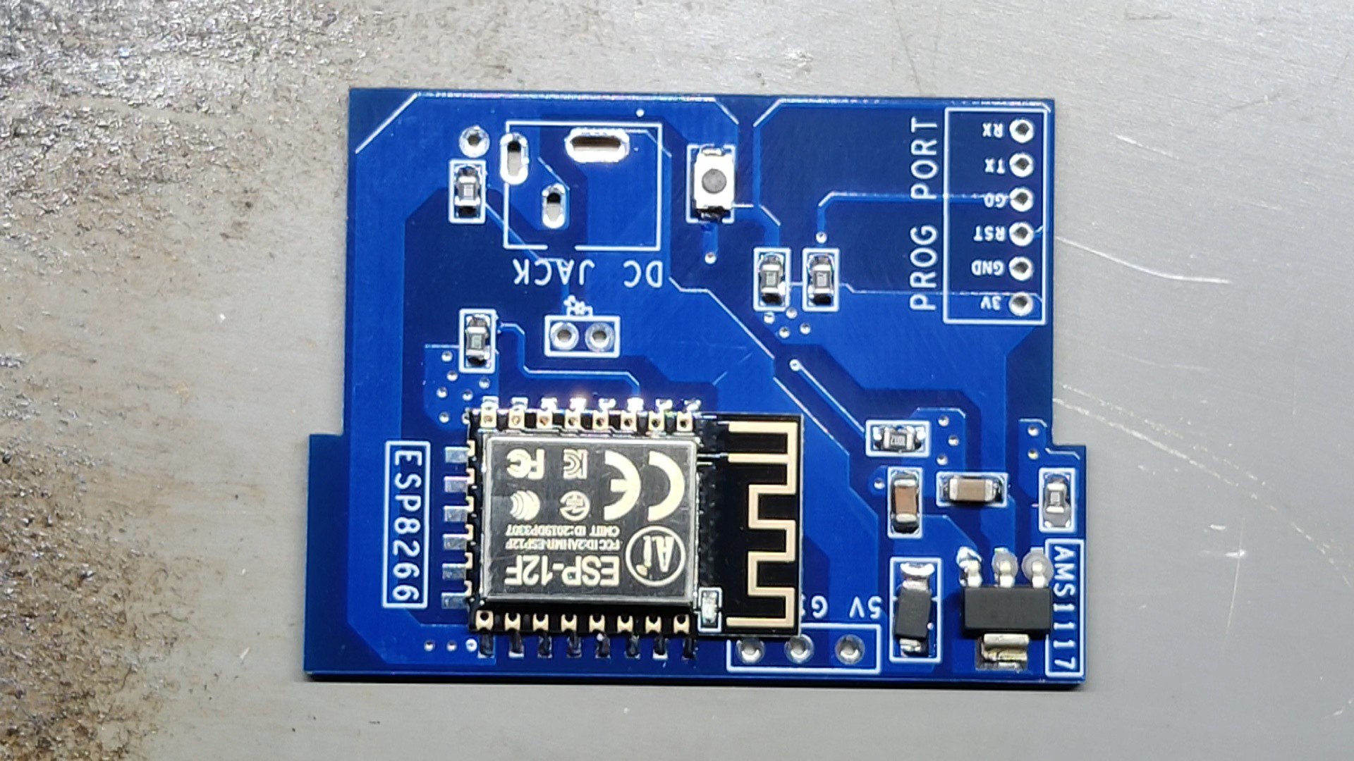
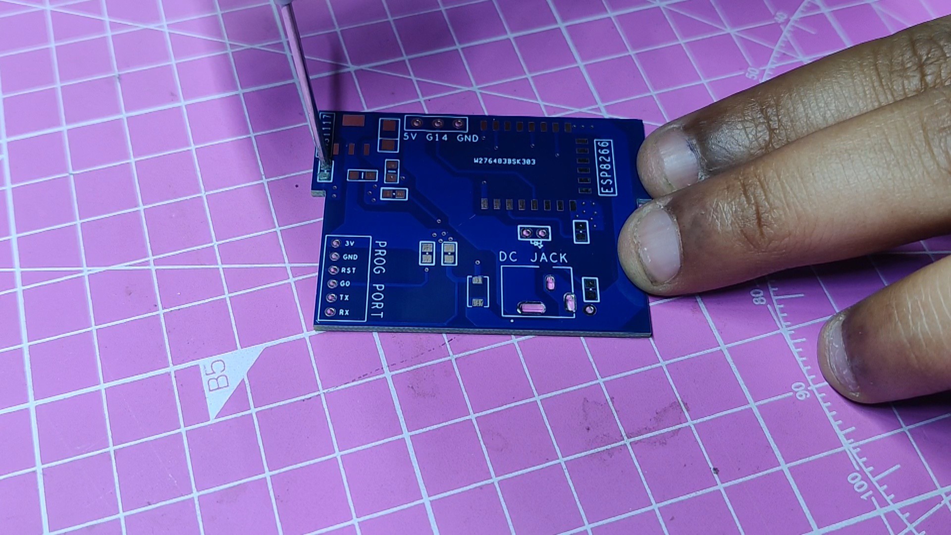
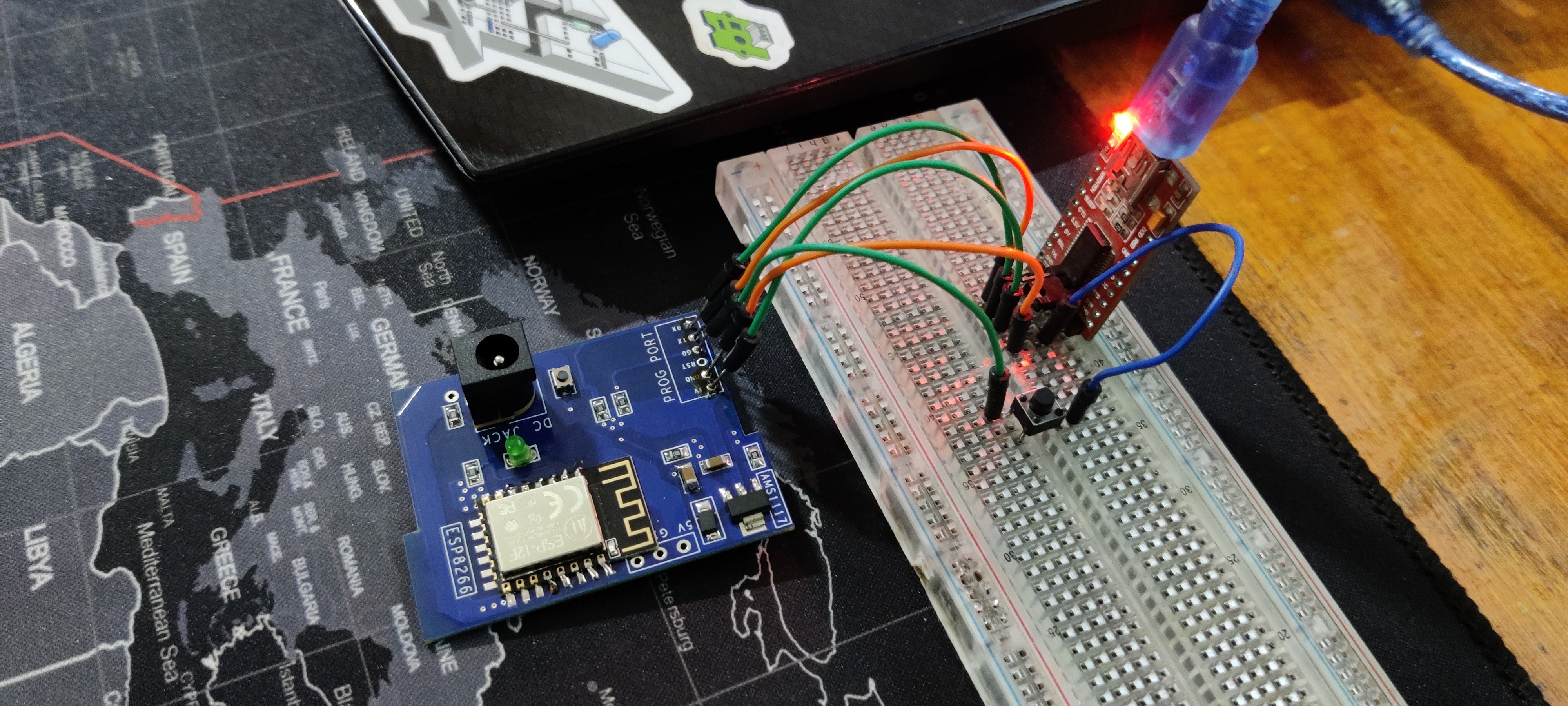
The second board was the ESP12F board.
As the name suggests, the ESP12F Board is a minimal breakout version of the ESP12F Model used in boards like the NODEMCU or other ESP8266 products.
In the schematic, we have added an additional AMS1117 3V version, which steps down the voltage coming from the input side to a stable 3V for ESP12F to function.
Similarly, we have use model from Fusio360 to make the PCB CAD outline.
After preparing the schematic and board files, both parts were sent to PCBWAY for samples.
PCBWAY Service
After completing the PCB design, we export the Gerber data and send it to PCBWAY for samples.
Two orders were placed: one for the main circuit and one for the LED board.
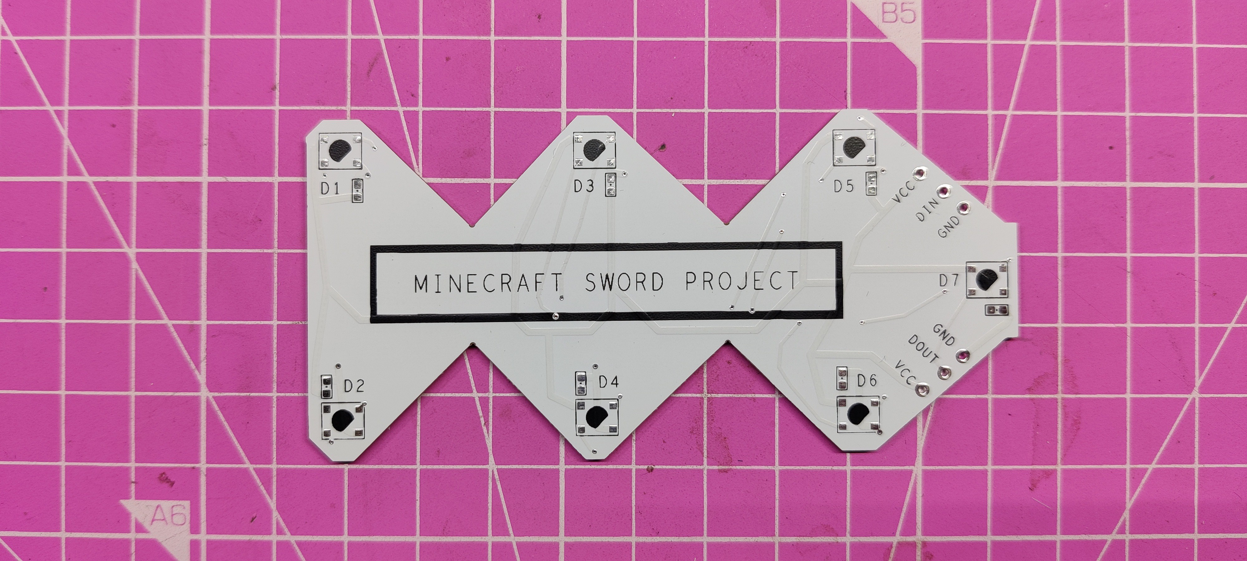
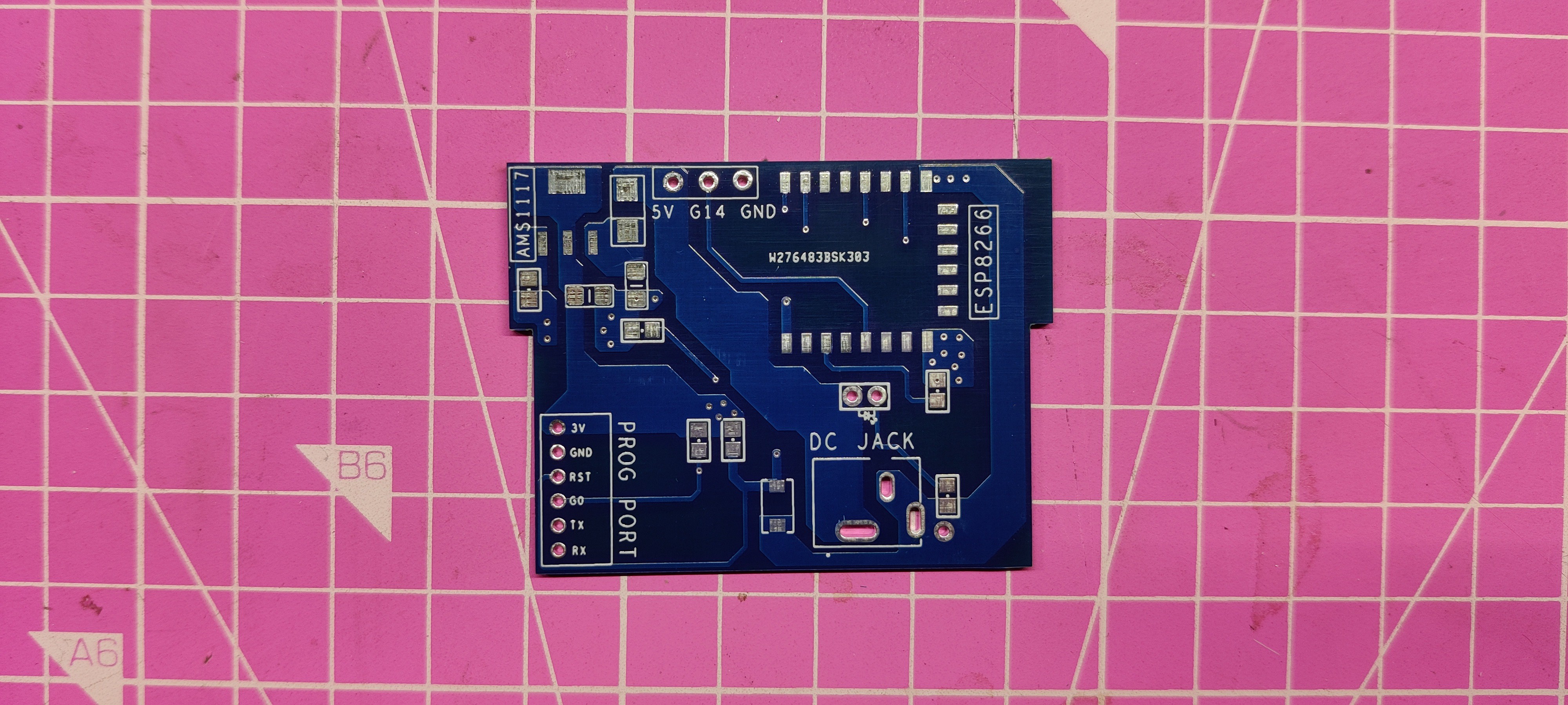
We place an order for a white silkscreen LED board and a blue silkscreen circuit board.
After placing the order, I received the PCBs within a week, and the PCB quality was pretty great. The silkscreen I used is completely random and asymmetrical, so it's pretty hard to make, but they did an awesome job of making this PCB with no errors whatsoever.
You guys can check out PCBWAY If you want great PCB service at an affordable rate.


 Alpenglow Industries
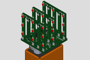
 Anool Mahidharia
 burkethos