Close
0%
0%

D1 Mini Tote

A version of Tote with the D1 Mini ESP8266 board as a brain.

Similar projects worth following

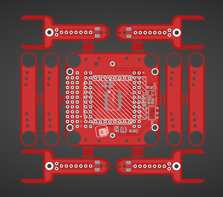
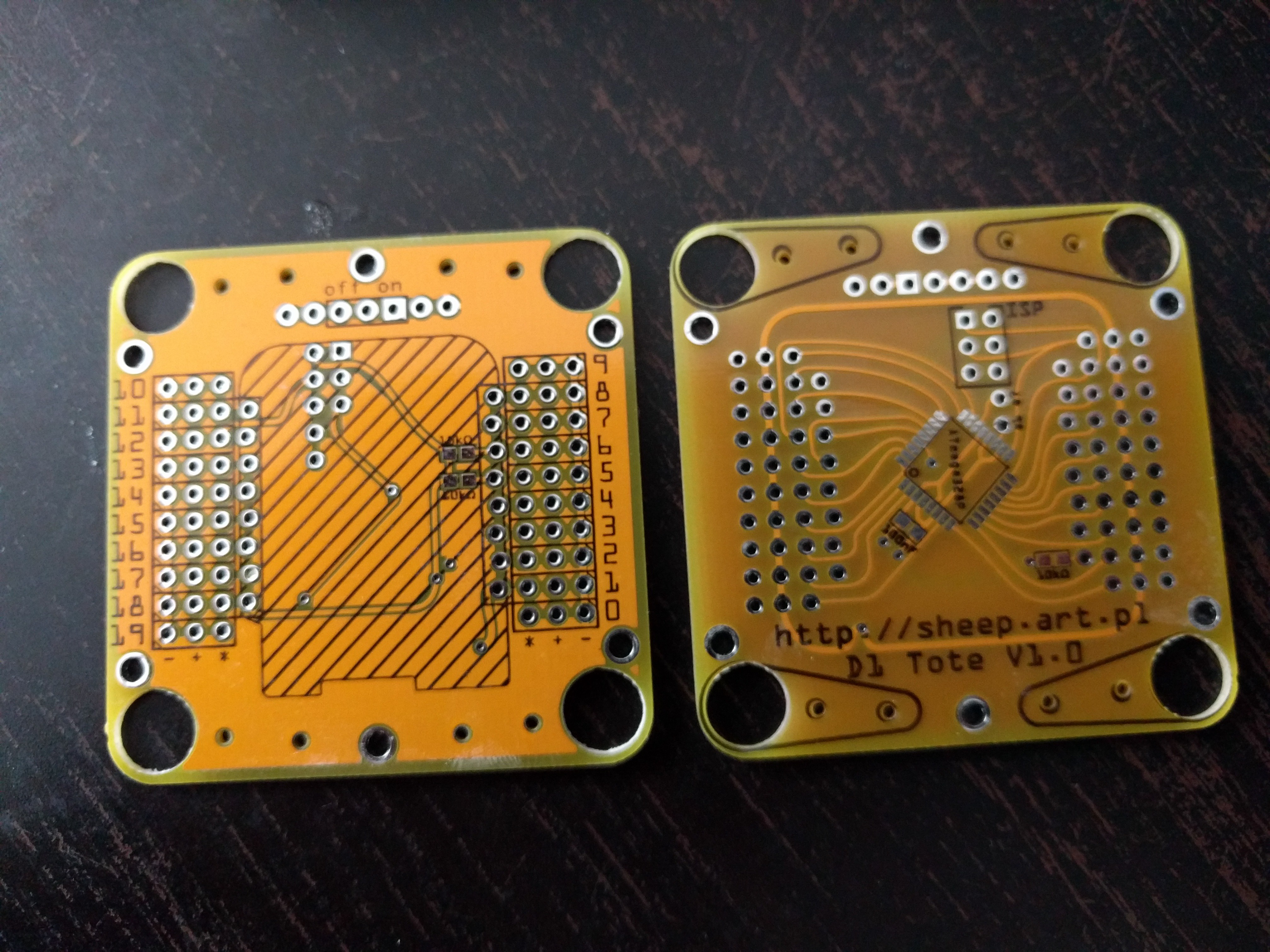
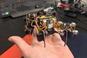
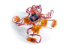
This is the next step of evolution of #Tote and #Tote HaD, the spider robots that were designed to be as simple and easy to build as possible, without sacrificing the proper walking algorithms. This time the focus is on making it easier to program and to modify by attaching additional hardware.

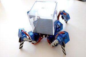
While Tote was focusing on building a proper quadruped robot without special materials and tools and as cheaply as possible, the subsequent projects focus on making the robot more reliable and easier to experiment with. The #SpiderWing project loosens the budget constraints, aiming to make a sturdier, stronger and more consistently reproducible robot. This project works in parallel to that, trying to incorporate the same improvements, but without rising the price too much. The two projects are meant to cover the conflicting needs of hobby robot developers.

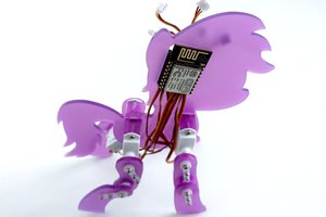
Of course, the overarching goal for both of them is to stimulate research in affordable and reliable legged robots, so that we can have devices like this at our homes one day.

  • 1 × D1 Mini ESP8266 development board
  • 1 × 3.7V 1S LiPo battery
  • 1 × SPDT Switch
  • 12 × SG90 Microservo
  • 24 × M1.2x4 screws

View all 12 components

  • One More Version

    deʃhipu05/07/2019 at 22:25 0 comments

    An advantage of having several similar projects, some long-term and some faster, is that the research and innovation you test in the fast projects can trickle back into the slower ones. This is one such example. When I started with this, I was mostly using ready modules for most things, and the PCB was just a way to hold things together. After some intensive development of #µGame, #PewPew Standalone and #Kubik M0, however, I figured out some ways of doing some of those things better with discrete components and with better mechanical design. So it's time to make a new version that will include all those improvements.

    Here it is:

    There has been changes. The D1 Mini footprint and the servo sockets have been rotated 90° degrees, so that the front of the robot is now to the left. That means that the battery is now sideways, and there is more room under the robot to fit the servos when the legs are in extreme positions (it will still require cutting off those "ears" from the servos). The body is still 5×5cm, but there are all those leg parts around it, so now the whole PCB is 10×10cm — which reflects the current reality of ordering cheap PCBs. It's the same idea as in #Kubik M0, however, the feet now have footprints for switches, so we can detect ground easily.

    There is no room for the battery protection and charging module anymore, instead there is a charging and a protection circuit directly on the PCB. I'm using a double switch for power, because when it switches off the power from battery, it also switches on the charging — this way I can use one USB port for both programming and charging. The servo sockets are rotated now, and stretched along the battery holder, so that they can go on the bottom of the robot and still leave enough room for the servos to rotate. I also added back some small prototyping area at the front of the robot, for mounting sensors, and also on the legs.

    Otherwise it's all standard stuff: a PCA9685 chip for PWM, a LiPo battery for power, and a socket for a D1 Mini to control it all.

  • Sturdier Legs

    deʃhipu06/15/2017 at 19:21 0 comments

    One of the common complaints I've heard about the mechanical design of Tote is that the legs are really too flimsy. I must have been lucky with the quality of plastic for the servo horns I got, because I didn't have a problem with that, but I came up with a solution anyways. And it's also a good use of the extra PCBs that you had to order (usually you have to order at least 3 PCBs).

    Here's how it looks like:

    I simply cut off the sides of the PCBs (using an older prototype in this case), and screwed the servo horns to those. If this is still to flimsy, you can even add a drop of glue under each of the horns, to make them really rigid.

    And what of the remaining PCB leftovers? Well, they are servo shields for the D1 Mini, and you can use them in your other projects! Nothing is wasted.

    I updated the design on the PCB to include holes, to make the sides easier to break off. You will still need to do it carefully, though, because I can't make it too brittle -- it's the body of the robot, after all.

  • More Brain Power

    deʃhipu06/14/2017 at 19:01 0 comments

    It has been a while since the last update, and there have been some developments. I will write about them in detail in separate logs when I get more time to do it properly. But today I just wanted to share a new part that I'm excited bout.

    There is a new development board, based on the ESP32 chip, but pin-compatible with the D1 Mini. It's called MH-ET LIVE D1 apparently (I know), and looks like this:

    The pins marked in white are compatible with the D1 Mini, and all the other pins are extra. Apart from the ESP-WROOM-32 module, there is the usual voltage regulator, CP2104 serial USB chip and a pair of mosfets for the reset circuit -- nothing special. All parts are on the same side of the PCB, the bottom is flat -- which is nice. I didn't lay my hand on that board yet, I'm waiting for it to arrive, but from I can tell it should fit the D1 Mini Tote PCBs. I might need to add a shield on the bottom, to make the extra pins stick out over the servo sockets, or use angled headers for the servo sockets -- we will see about that.

    So why so excited? Well, initially I couldn't decide whether to go with the D1 Mini or the Feather boards. I like the form factor (and price) of the D1 Mini better, but Feather has more options for me to choose from (I even got an ESP32 Feather recently, but didn't have a chance to do anything with it yet). So I started both this project and the #SpiderWing. Now seeing that the D1 Mini footprint becomes a kind of a standard, I'm hoping that both versions will become equally viable.

  • Battery Protection

    deʃhipu02/20/2017 at 09:21 0 comments

    I did some more work both on this project and on the #SpiderWing. I debugged the leg IK code finally -- it was all about reversed servo directions. I also tested different parameters for the creep gait, and I can tell it will take some time to tune this properly.

    However, in the process of doing that, I ran the LiPo batteries on those robots to dangerously low voltage levels. Fortunately I noticed and re-charged them quickly, so hopefully the damage is not that big, but this made me actually go looking at the schematics and reading datasheets.

    It turns out that neither the Adafruit Feather not the D1 Mini Battery Shield have a built-in overdischarge protection, as I assumed they would. They only have a charger and a voltage regulator (a boost converter in the case of the D1 Mini). They assume, apparently, that the battery has the protection circuit built-in. Of course the 16340 batteries that I'm using have no such thing. So it's back to the drawing board.

    I considered various options:

    • add the battery protection circuitry on the board (in form of a ready chip)
    • add the battery protection as a ready module
    • add a battery charger module with the protection circuit included
    • add a voltage divider and connect it to an analog pin of the board, and monitor voltage in software in Python
    • add a voltage divider and connect it to an analog pin on the ATmega, and monitor voltage in software in C on the servo controller

    All of those have their advantages and disadvantages, and I think I'm going to choose different options for the two different designs.

    For the D1 Mini Tote, I don't care much about how complex the board will become -- it requires soldering of SMD chips anyways, so if I ever make this available, that will probably be with the board pre-soldered. In that situation, a hardware battery protection is a better thing -- it works even if there is a bug in your software, or when that crashes. I also don't like the battery shield very much. So I decided to go with a battery charger module with a built-in voltage protection on it. I had a few of those on hand already, and I tested them briefly -- they seem to work just fine. So I reworked the PCB to include the pins for the charging module, and to not require the battery shield anymore. There will still be a separate USB socket for charging -- there is no way I can access the data pins on the D1 Mini to connect the sockets together, and the robot will still have to be switched on for charging -- I have bad experiences with leaving anything connected to the battery with the switch in the off position: I want the switch to cut the battery completely.

    For the #SpiderWing, I went with a voltage divider initially. It would be perfect to just connect it to A6 or A7 -- the analog-only pins that I'm not using anyways -- of the ATmega, however, they are not broken out in the DIP package. So now I have a choice between using one of the servo pins (which I really could, since I have 8 more than I really need), or using the Feather's analog pin and run the check in Python. I made some PCB designs for both approaches, but just now, while I was writing all this, I had another idea. The ATmega includes internal reference voltage that I can measure against the voltage the chip is powered from. That means, that if I power the ATmega directly from the battery, I can check the battery voltage without the need for any extra components or pins. Well, OK, I will need a filtering capacitor then, because the servos make a lot of noise, but it should work. Unfortunately, right now I'm powering the ATmega from the 3.3V pin of the Feather -- because it's nice, stabilized and filtered. In any case, I would really prefer to have the check in the ATmega, and not on the Feather -- it's more robust that way against users uploading their own programs.

  • Smaller ATmega

    deʃhipu02/18/2017 at 18:26 3 comments

    The ATmega8 chips arrived, and I decided to try and see if my servo controller code will run on it equally well as on the ATmega328p that I used previously. After soldering it to the PCB (I'm getting better at it) I edited the Makefile to change the target, ran it and... got errors. Looks like a couple of registers got renamed, so I took the datasheets, compared them and made the appropriate changes. This time it compiled, so I flashed it to the chip, and... it doesn't work. I looked again, and realized that the fuses are completely different for this chip! To the avr fuse calculator. I changed the fuses in the makefile, flashed again and... it works!

    I still need to properly debug and finish the Python code for walking -- the last weeks were a bit too busy to setup the testing and focus on this properly, but I hope I will get it done soon.

    By the way, I also received the PCB for the #SpiderWing -- the Feather version of this. I'm going to be developing them both in parallel for now.

  • Debugging

    deʃhipu01/29/2017 at 18:48 0 comments

    I have the little guy assembled (I stole the legs from my first Tote prototype), and it works quite well. However, software is the hard part.

    First I had to remap the servos in my servo controller firmware to make them agree with what's written on the PCB -- that should make it much easier to debug everything in the future. I also wrote the Python side of the communication with the servos, and there I had my first problem -- when sending the servo positions too fast one after the other, I get bus errors. For now I just catch them and retry, but I suspect I will need to increase the clock stretching timeout.

    Second, the Python code for Inverse kinematics -- I used the original code that I have written years ago for #µKubik quadruped robot, and it seems to work without problems. Yay. Except for some stupid mistakes I made, like multiplying everything by 0, which of course took me hours to find. Oh well.

    The gait code is more problematic though. I used the code I wrote for #Tote HaD, but it doesn't seem to be behaving exactly as I wanted. I'm still figuring out what is wrong -- it's probably something trivial like a reversed angle somewhere or a leg going out of range -- but no success yet.

    You can see the current status on the movie:

  • Surprise PCBs

    deʃhipu01/26/2017 at 16:59 0 comments

    This is the effect of my brainstorming about the best board to use for Tote's brains. I initially choose the D1 Mini board, and designed a couple of PCBs to use it. However, I did that late at night, and in the morning I didn't remember that I ordered one of the designs. Then I changed my mind and decided to use the Adafruit Feather boards instead. A few weeks later I received the surprise PCBs. Since I already have them, I might as well just built and program it -- especially since the code is going to be the same for both versions of Tote anyways, and I'm still waiting for the other PCBs.

View all 7 project logs

  • 1
    Mechanical Assembly

    For mechanical assembly, follow the instructions at http://tote.readthedocs.io/en/latest/assembly_v5.html#legs

  • 2
    Electronics

    Solder the headers, PWM chip and resistors onto the board. Add the power switch and battery holder. Connect the servo plugs.

  • 3
    Programming

    Copy the python code from project's repository onto your D1 Mini using Adafruit's Ampy utility. Plug the D1 Mini into the PCB.

View all 4 instructions

Enjoy this project?

Share

Discussions

Similar Projects

Does this project spark your interest?

Become a member to follow this project and never miss any updates