Close
0%
0%

PolaPi-Zero

Yet another Polaroid-like camera. Now with flavor! RapsberryPi Zero, Python, Memory-LCD, less wiring. It's all about monochrome.

Similar projects worth following
This is the second iteration of an Instant-Printing-Point-and-Shoot camera. No more thermal printer hack, and just Python.
It is base on a Raspberry-pi Zero, a Sharp memory LCD for 'live-view' and review and the Nano thermal printer from Adafruit.

First project : https://hackaday.io/project/7176-polapi

As I gave to someone the first version of the PolaPi, I had to rebuild it. This time I tried to simplify a bit the process, the printer hack is not needed anymore. Please find below some explanations about some hardware choices and the software.

Hardware

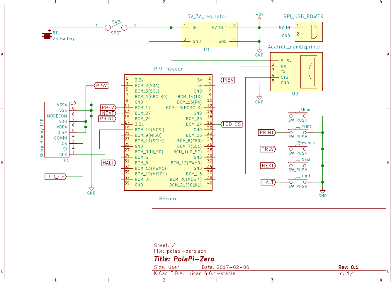
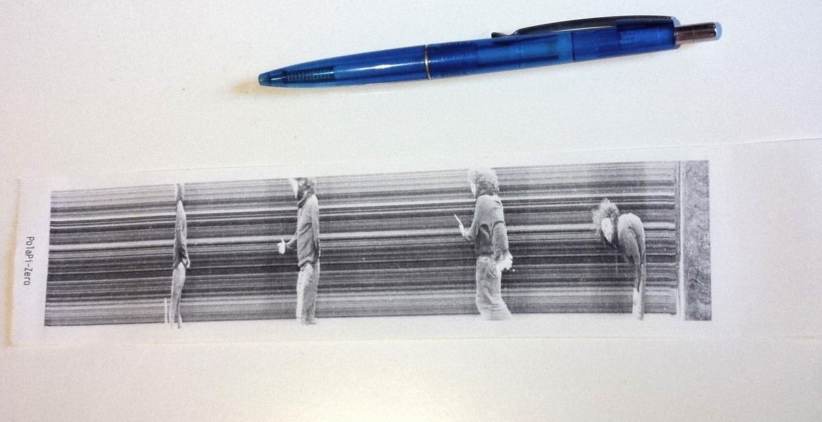
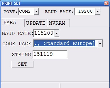
First of all, the pinter. The Adafruit nano printer, despite it's smaller than the regular one, it has a serial CTS pin. This means we can prevent the internal buffer overrun. However I still used the small windows program to increase the serial speed from 9600 bauds to 115200.

The little Sharp memory-LCD is perfectly visible on sunlight, and as the printer do, displays only black or white pixel. It needs a small SMD FFC-10P 0.5mm adapter and connector. It uses SPI but with an inverted logic for the chip select, that's why another GPIO is used.

I oversized the powering I suppose, but the printer can take quite a lot of current. Mainly because I recycled the parts, I used a 3A 5V regulator and a 2S lipo battery. For the moment I use a separate specialized balance charger.

The switch I had to turn it on and off has a little led inside. I reused it in place of the activity led of the raspberry pi zero. The on board led is de-soldered and rewired to the swith one.

Software

This project is a good excuse to start learning Python (finally). It is more popular than Java and a lot of work is already done. The code I made so far, not really the most elegant and explain a bit later, is available on this Github. (polapizero_04.py is the main for the moment) If you manage to re-build the same hardware, I've put a 2GB SDcard image for the raspberry-pi zero on dropbox here.

For the LCD, I'm not enough experienced in C/linux drivers to write a FBTFT module. Then I used the work done by wrobell and his Python library dedicated to the LS027B7DH01. That's why for the moment the screen refresh rate is limited to 8fps. The library allows to set directly a PIL image on the display. I was a bit puzzled about how to build the lib. autotools/autoconf is used and gave some errors at first.

For the printer, Adafruit made a nice library which can handle directly images. In my case I just had to adjust it a bit to let the hardware manage the CTS line and then remove the delays anticipating the buffer filling.

The raspberry pi serial has to be setup as well to manage the CTS line. Here mholling explained everything on his github repository. However the command lines have to be launched reach boot, then added to rc.local

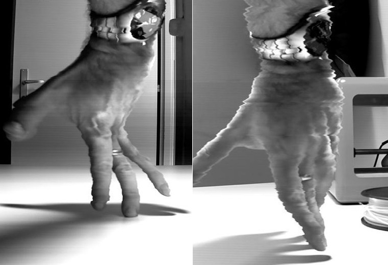
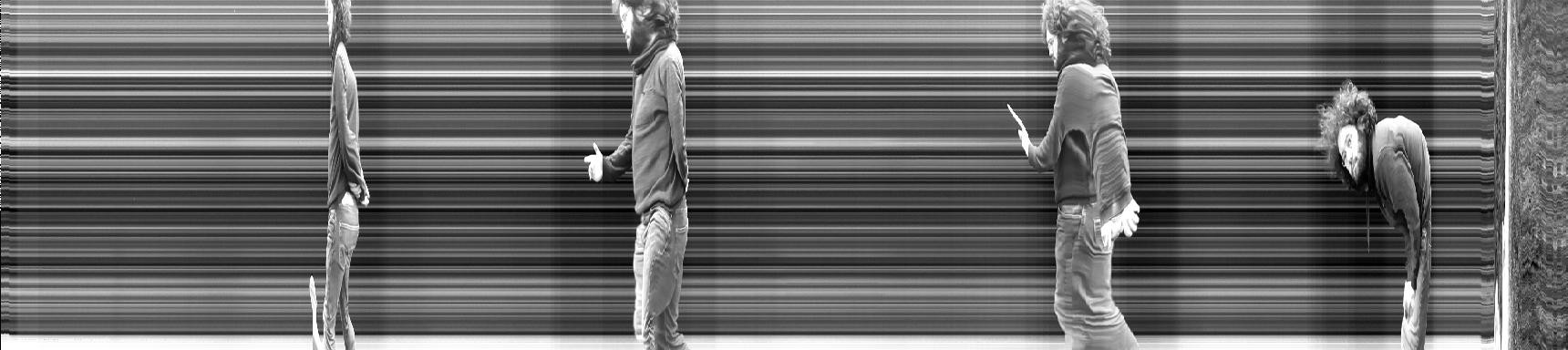
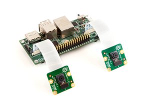
The raspberry pi camera has its nice python library, which is really fast and expose a lot of settings. To avoid as much as possible the latency between the button press and the picture recording, I used two threads each using a splitter port.

The case

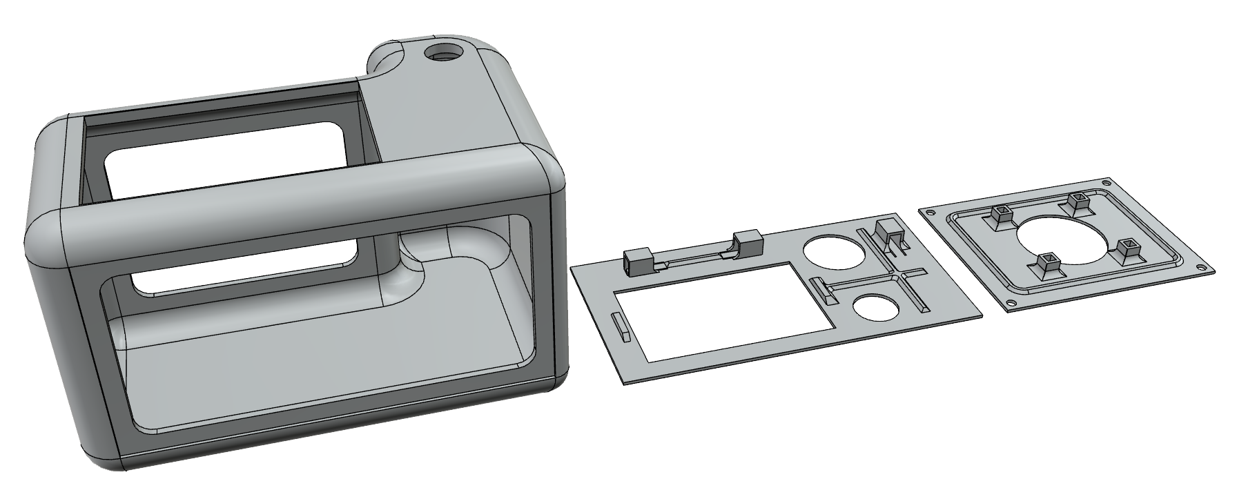
This time I tried to get something a bit better for the case. I spent a bit of time on the autodesk 123D design software and used the www.3dhubs.com services. I'm quite happy with the result, and the hub was very fast.
The 123d file is on github, polapizero013.123dx, as well as .STL files.

[to be continued]

View all 8 components

  • Pillow tweaking, Ordered Dithering

    Muth05/07/2017 at 09:16 0 comments

    I was not too happy with a flickering effect during 'live-view'. Very visible on large gray area, where the black and white pixels should be alternate in a king of chess board pattern in order to create the gray illusion. With the error-diffusion method (Floyd-Steinberg), this alternating pattern will change randomly every frames. Maybe due to the LCD latency, flickering appears.

    So a solution could consists to change from the pseudo random pattern of this Floyd dithering to the ordered method. The last one is less precise, but the fix Bayer matrix gives constant patterns.

    The flickering is not clearly visible on this video, but the changed method gives a more smooth animation.

    To reach this point, it was inconceivable to write the Ordered dithering algorithm in pure Python. I tried though, but far too slow as predicted. The solution was to directly implement that code in the compiled imaging Python library, Pillow. The following will be a summary of my Pillow compilation adventure...

    Pillow, compiling Python lib

    According their documentation, PIL (original and older version of the library) and Pillow cannot coexist. So first step is to uninstall them. Be sure to have the Python tools, and then I uninstall the previous version with PIP:

    sudo apt-get install python-dev python-setuptools python-pip
    sudo pip uninstall Pillow

    Then I followed the Pillow building tutorial, and get and uncompress the sources:

    wget https://pypi.python.org/packages/93/73/66854f63b1941aad9af18a1de59f9cf95ad1a87c801540222e332f6688d7/Pillow-4.1.1.tar.gz#md5=f2565954955c8d10f3b4f1f72f852bf7
    tar -zxvf Pillow-4.1.1.tar.gz
    Some external C library are needed:
    sudo apt-get install libjpeg8-dev zlib1g-dev libfreetype6-dev liblcms2-dev libwebp-dev tcl8.5-dev tk8.5-dev python-tk
    And then I manage to get everything compiled and installed :
    cd Pillow-4.1.1/
    sudo python setup.py build
    sudo python setup.py install
    Inserting the Ordered dithering code

    Now I used this very nice document of Lee Daniel Crocker to get a well written C code. It has to be inserted in /Pillow-4.1.1/libImaging/Convert.c :

    static Imaging tobilevel(Imaging imOut, Imaging imIn, int dither) {
    	int pattern[8][8] = {
        { 0, 32,  8, 40,  2, 34, 10, 42},   /* 8x8 Bayer ordered dithering  */
        {48, 16, 56, 24, 50, 18, 58, 26},   /* pattern.  Each input pixel   */
        {12, 44,  4, 36, 14, 46,  6, 38},   /* is scaled to the 0..63 range */
        {60, 28, 52, 20, 62, 30, 54, 22},   /* before looking in this table */
        { 3, 35, 11, 43,  1, 33,  9, 41},   /* to determine the action.     */
        {51, 19, 59, 27, 49, 17, 57, 25},
        {15, 47,  7, 39, 13, 45,  5, 37},
        {63, 31, 55, 23, 61, 29, 53, 21} };
    
    //    [ ... ]
    		
    		if (dither == 1){
    			int l;
    			/* map each pixel to black or white, using ordered diffusion */
    			ImagingSectionEnter(&cookie);
    			for (y = 0; y < imIn->ysize; y++) {
    				UINT8* in  = (UINT8*) imIn->image[y];
    				UINT8* out = imOut->image8[y];
    
    				for (x = 0; x < imIn->xsize; x++) {
    					/* pick closest colour */
    					l = CLIP(in[x] / 4);
    					if (l > pattern[x & 7][y & 7]) {
    						out[x] = 255; 
    					} else {
    						out[x] = 0; 
    					}
    				}
    			}
    			ImagingSectionLeave(&cookie);			
    		
    		} else {
    \\ [ ... ]
    The nice thing is this was foreseen in the Pillow development, as Dither variable could takes yet defines constants in /Pillow-4.1.1/PIL/Image.py :

    # [...]
    # dithers
    NEAREST = NONE = 0
    ORDERED = 1  # Not yet implemented
    RASTERIZE = 2  # Not yet implemented
    FLOYDSTEINBERG = 3  # default
    # [...]
    
    The Convert.c file I modified is probably not suitable to request a pull in the library, but I've put it in the PolaPi-Zero git repository.

    I will soon update the SD card image with this last version.

  • Another screen

    Muth03/29/2017 at 16:42 0 comments

    As said, the memory LCD choice was mainly because it was already lying on a box somewhere in the possibly-will-be-useful pile of stuff. However it's not easy to find and not easy to solder.

    I had a bit of time to quickly test what could be the result with a cheap oled screen. The 128x64 monochome OLED based on the SSD1305 /6 are quite common.

    I used the Adafruit python SSD1306 library and the python picamera one. It gives funny results (too bad PIL library not implements ordered dithering instead of Floydsteinberg) but it's really at the lower resolution limit for a useful viewfinder :

    Preview code is quick and dirty :

    '''
    Created on March 13, 2017
    @author: muth
    '''
    from __future__ import print_function
    from io import BytesIO
    from time import sleep
    import picamera
    from PIL import Image
    from time import sleep
    import time
    import Adafruit_SSD1306
    
    S_WIDTH = 128
    S_HEIGHT = 64
    S_SIZE = (S_WIDTH, S_HEIGHT)
    P_WIDTH = 768
    P_HEIGHT = 384
    P_SIZE = (P_WIDTH, P_HEIGHT)
    
    class MyOutput(object):
        def __init__(self):
            self.size = 0
    
        def write(self, s):
            global oled
            
            image = Image.frombuffer('L', P_SIZE, s, "raw", 'L', 0, 1)
            image.thumbnail(S_SIZE, Image.NEAREST)
            image = image.convert('1', dither=Image.FLOYDSTEINBERG)
    #         image = image.convert('1', dither=Image.NONE)
            oled.image(image)
            oled.display()
    
    # Initialize oled.
    oled = Adafruit_SSD1306.SSD1306_128_64(rst=24)
    oled.begin()
    oled.clear()
    oled.display()
    oled.set_contrast(2)
    
    with picamera.PiCamera() as camera:
        camera.rotation = 180
        camera.resolution = P_SIZE
        camera.framerate = 60
        camera.contrast = 50
    #     camera.start_preview()
        camera.start_recording(MyOutput(), format='yuv', resize=P_SIZE)
        sleep(30)
        camera.stop_recording()
        sleep(1)

  • Slit-scan Mode

    Muth02/13/2017 at 17:38 0 comments

    finally made some test about a slit-scan mode. If you don't know yet, it is worth to google-it. It is on version 0.8 and in the last SDcard image.

    For now I implemented 2 types scan. One where each vertical lines are recorded at around 20 per second:

    The pictures above are taken with this first mode, and the camera standing vertically. It's a king of very slow 'roling shutter' effect.

    Imagine the funny result you can achieve scanning a face slowly rotating ;)

    In the second scan mode, only the central vertical line is recorded and stacked to a image which can be the width you want. Be creative :)


    To launch these modes, while in 'liveview', use the button 'next' for the first mode and 'previous' for the second. Each mode can be interrupted with the trigger button.

  • Around 20 fps

    Muth02/13/2017 at 17:01 0 comments

    I figure out how to reach a better frame-rate on the LCD screen. On possibility I didn't tested is to grab the video frames frome the picamera library. I had doubt the RPi zero can transform fast enough the image but it's doing well at 20 fps. There some drops, but very acceptable, and the CPU is at about 40% and 0.7 Load av'.

    The code start video recoding :

        liveview = LiveView()
        camera.start_recording(liveview, format='yuv', resize=SCREEN_SIZE)
    and the class LiveView must implements write(self, string) :
    class LiveView(object):
        def __init__(self):
            pass
    
        def write(self, s):
            global lcd
            image = Image.frombuffer('L', (416, 240), s, "raw", 'L', 0, 1)
            image = image.crop((8, 0, SCREEN_WIDTH+8, SCREEN_HEIGHT))
            image = ImageOps.invert(image)
            image = image.convert('1')
            lcd.write(image.tobytes())
    
        def flush(self):
            print('Stop LiveView') 

    The thing about the 416 pixel width instead of the 400 of our screen (and the needed crop) is due to the fact that the camera return a modulo 32 pixels dimension video frames.

    Sees v0.6 on github.

View all 4 project logs

  • 1
    Step 1

    Raspberry Pi Zero Setup

    At first, setup the Zero might be tedious. There is only one usb port. Google 'raspberry pi zero setup without monitor' and you'll find very nice tutorials.

    However if you want to just duplicate the polapi-zero, in order to setup the SD card, download the image from the project dropbox, and write it according the raspberry pi instructions:

    https://www.raspberrypi.org/documentation/installation/installing-images/README.md

    If you plan to access the raspberry pi with wifi and plugged an usb wifi adapter, once the image is written, you can access a FAT32 partition on the SDcard named /boot. On this partition you can add a file named wpa_supplicant.conf and put the network information inside:

    network={
    ssid="YourWifiNetworkName"
    psk="TheMagicPassword"
    }
    This file will be automatically copied in /etc/wpa_supplicant/ at boot time. If you download the polapi-zero image, you should find a file wpa_supplicant.conf.bak that you can duplicate.

    The image is just the official Raspian image, with a samba server running, SPI LCD driver setup, Serial CTS enable, etc... Login and password are the default one.

  • 2
    Step 2

    Hardware

    Probably the most delicate time is the beginning is to connect the Sharp LCD screen. I have found on ebay some adapter board for the small 10 pin ribbon cable, but I finally solder it myself. This kind of adapter board with this king of connector helps a lot.

    The printer receives data on a serial port, and by default the speed is slow. And there is a software way to change from 19200 bauds to 115200 thanks to this program: Link. As it is a windows program, and we need a USB to 5v TTL serial converter, such as this one. Power the printer, connect the gnd-Tx-Rx, and on the printer program set the right port, the previous speed (19200 in my case), the new speed (115200), code page US (it's the character-set ) and press SET.


View all instructions

Enjoy this project?

Share

Discussions

stafvdz wrote 11/28/2023 at 06:51 point

hey its a realy cool project ps: i am gona make it

but quick question what sort of buttons did use for all the buttons?

and the power switch?

and why dont u connect the screen with the hdmi port thats on the pi zero?

  Are you sure? yes | no

Christoph wrote 06/10/2020 at 20:24 point

Hi guys,

I'm not sure if this is maintained anymore since it's been a while.

I built everything, everything work fine but printing. Just the first 1-2cm of the photo come out properly, the rest is random alphanumeric something. I'm using the Arduino Mini (not the Nano), but protocol should be the same, right? I did update the Baud rate and the Code page as described.

I'd appreciate if somebody could help me out!

Prints: https://1drv.ms/u/s!Atw_djMOGEe8g6gg0a7ZIaPIIGPZrA?e=LyIH2Y

Printer settings: https://1drv.ms/u/s!Atw_djMOGEe8g6gnjr4DGydAEig_GA?e=mMAb7P

Thank you!

  Are you sure? yes | no

Juan Antonio wrote 08/28/2019 at 18:27 point

This project is really cool! Great job! 

I want to make my own polapi using your SDcard image, but i am really bad programming...

What does this image include?

If I burn your image using the same hardware, would the camera be "plug and play" or would I have to install something else?

Thanks!

  Are you sure? yes | no

Bing7z wrote 07/11/2018 at 05:06 point

Where to buy buttons??:)

  Are you sure? yes | no

benstokerdan wrote 02/18/2018 at 20:48 point

Does any one know where I can get this connector? They are out of stock and I can't seem to find it anywhere else.

https://www.digikey.com/product-detail/en/molex-llc/0514411093/WM6474CT-ND/1089691

  Are you sure? yes | no

rene wrote 12/20/2017 at 19:38 point

Hi

I am going crazy and need some help!

1. what is the login and password?

  Are you sure? yes | no

Muth wrote 01/19/2018 at 14:17 point

Hi, sorry for the delay,

It is the default login/pwd of Raspbian : pi/raspberry

  Are you sure? yes | no

wadenatlas wrote 09/07/2017 at 22:41 point

What battery and converter are you using? Where did you get it and what are the specs? Thanks!

  Are you sure? yes | no

Muth wrote 01/19/2018 at 14:26 point

I used a switching 5V regulator, 3A rate, found on ebay : 

https://www.ebay.fr/itm/New-High-quality-LM2596S-Power-DC-DC-Buck-Converter-Step-Down-Module-5V-3A-M1-02/192368358049?hash=item2cca0c32a1:g:r7sAAOSwqfJZebz1

Any 5V DC/DC converter that can take at least 9v on input and deliver few Amps would work. For example 2S UBEC from hobbyking :

https://hobbyking.com/fr_fr/hobbykingtm-micro-ubec-3a-5v.html

  Are you sure? yes | no

manoharjj wrote 08/31/2017 at 13:27 point

Hey, this is an amazing project! Really great job!!

I want to build one too, because Instant cameras fascinate me a lot and tried to read myself into it already and bought the parts, but I am a REAL NOOB.

So I don't really know how to build the hardware or to connect what with what.

I would be really grateful if you could guide me a little.

Which tutorials should I do, to understand how this setup works?

Just taking a picture and getting the printout is great enough, so I don't need so much functionality as in your project, then it might be easier for me to set it up

Thanks :-)

  Are you sure? yes | no

Viper-Gtr wrote 06/22/2017 at 09:17 point

Hi,

I wanted to build everything exactly the same way. But my LCD just displays random pixels and nothing on the screen change at all.

Have you connect any pullups? And do you leave LCD-pin 4 unconnected?

  Are you sure? yes | no

Muth wrote 06/22/2017 at 20:06 point

Hi!
Sorry to see it's to working at first. It works strait for some people, but I double checked the connections. Yes I leaved unconnected pin-4 as the this 'inversion' should be done by software, set by the pin modecom pin. I didn't use pullups resistors. I take a closer picture of the connections:

 [dropbox.com/s/5uaq4697i9l3e8r/IMG_20170622_213238.jpg]

Only 5 wires, where 10-9-8 and 7-6-5 are solder together in the back of the adapter board. (yes this adapter board inverted the pin number with this particular connector)

Did you start from the raspbian image I posted ?

  Are you sure? yes | no

Viper-Gtr wrote 07/14/2017 at 09:54 point

Yes exactly, I have directly used your imagne to my SD card.
So, to prevent errors with the wiring, I made a PCB (plus LiXX charge circuit and DC / DC converter as sandwitch) as a hookup to the RPi.
https://oshpark.com/shared_projects/X5R6LC6K
So now i have to wait for the boards. The shipping normaly take about 4-5 weeks from OSH to Germany.

  Are you sure? yes | no

Muth wrote 07/14/2017 at 12:13 point

Woaw, what a nice board ! Very clever to stack everything, and very clean build ! I would be pleased to see the final result :)

You should make an hackaday project page for that ! Or if you prefer, put your add-on on this page.

About the screen, I took a new SD card and re-write the image on it. And the screen is working on my side. Did you saw the CS pin used on the raspberry pi is not the SPI CS pin but the pin18/BCM_24 ? It is imposed by the 'smemLCD' python library. (a bit strange, I supposed the author did that because the LCD works with CS active at high, but the RPi SPI can be configured to the same behavior...). An other thing I can imagine (but highly speculative), did you power the screen with the RPi GPIO 5v ? If not, it may be possible the screen is on before the RPi initialized the GPIOs, and then received garbage signals ?

I'm trying to make another one, and yet start to receive parts. I would like to add a small ADC for the battery level indication on the screen. I'll let you know if I encounter the same probleme you have with the screen.

Thanks for sharing your experience, building and improving the Polapi !

  Are you sure? yes | no

Viper-Gtr wrote 01/19/2018 at 08:26 point

Hi Muth,
it#s been a long time ;-)

i have improved my pcd a little bit and everything is running fine now on the breadboard ^^.  This means i can take pictures and can print them out, but i don't really get the funktion from the "hold" button. Because everything freezes when i push it.
Can you put anywhere a discripion about the "menu" from the PloaPi?

  Are you sure? yes | no

Muth wrote 01/19/2018 at 10:18 point

Hi !

So pleased to ear about your project ! And I'm glad it's working !

For 'Halt' button, I remember now. It has two different function depending if you are in the picture review mode, or the 'live-view' mode.

- if you press it in review mode, it will shut down the raspberry pi (>sudo halt) properly. that's why everything is freezing. To know when the raspbian shutdown process is finish and when you can safely switch off the main power, the activity led makes three regular on/off cycles and stays off.

- If you press the 'halt' button in 'live view mode', it should change the dithering algorithm between 'ordered' to 'error diffusion'.

You're right, I should draw a flow chart, it's quite unclear as it is now.

  Are you sure? yes | no

Viper-Gtr wrote 01/19/2018 at 13:00 point

So now, everything is clearer ^^.

someware you'd wirtten that you like to put an ADC in this projekt, which one is your favorit? I'm asking, because i like to remake my hole board to get a more universal design. My decision is on the ADS1115. If you want, then i take it direktly on the board.

  Are you sure? yes | no

Muth wrote 01/19/2018 at 14:16 point

The idea of the ADC was only to get the battery voltage, I think ADS1115 would be good, the only contraint is the communication that should be I2C, as the SPI is taken by the screen. And ADS1115 is well I2C. Maybe there is a need of 2 resistors to divide the 7.4v to fit the ADC range as well.

  Are you sure? yes | no

Viper-Gtr wrote 01/21/2018 at 23:10 point

https://oshpark.com/shared_projects/dLeRNDb5

so, thats it.
I added the ADS1115 (the 3 other pins are on solpads).
A little beeper is also onboard (optional).
The buttons are on normal pins now.

9V for the printer now comes from the boostup and the printer pins are sorted right now.
The display-pins are doubled on solpads now.

I just had some terrible interferences on the screen so some more 100n are right on.

Everything as smd is on top-layer.
And for sure i added a LED as backlight (experimental).


The boards are ordered at OSH and now it's waiing time again ;-)


  Are you sure? yes | no

racer993 wrote 02/10/2017 at 13:46 point

  Are you sure? yes | no

Thomas Kremser wrote 02/09/2017 at 18:29 point

is it possible to use your polapizero.py with a RPI3 and a normal GPIO Display (Adafruit eg.)

  Are you sure? yes | no

Muth wrote 02/10/2017 at 11:16 point

Hi,

I tried first with a RPI3, but I didn't manage to make the hardware CTS working. I though I can then use a standard GPIO, and pause the serial data flux when the printer CTS rise. Unfortunately, the raspberry pi and/or the serial python lib have an output buffer as well. So when you stop transmitting in the python program, it actually continue to send few bytes, which overrun the printer buffer.

So as it is, the program wont work on RPI3. It is however possible to make one for RPI3, and use intact the adafruit thermal printer lib. Unfortunately, the printer will make some pauses, resulting in white verticale lines on the print.

Using a GPIO display is a well possible. You have then to remove the SPI LCD code part as the camera preview will be visible, and use a different strategy to show the images files. I'm not yet familiar with python libraries but you may be need the server X to show an image ?

  Are you sure? yes | no

Simon Fitton Davies wrote 02/09/2017 at 10:00 point

Great project.

Can I ask what lens is shown in the pictures? It is not listed in the components.

Thanks

  Are you sure? yes | no

Muth wrote 02/10/2017 at 10:57 point

  Are you sure? yes | no

Similar Projects

Does this project spark your interest?

Become a member to follow this project and never miss any updates