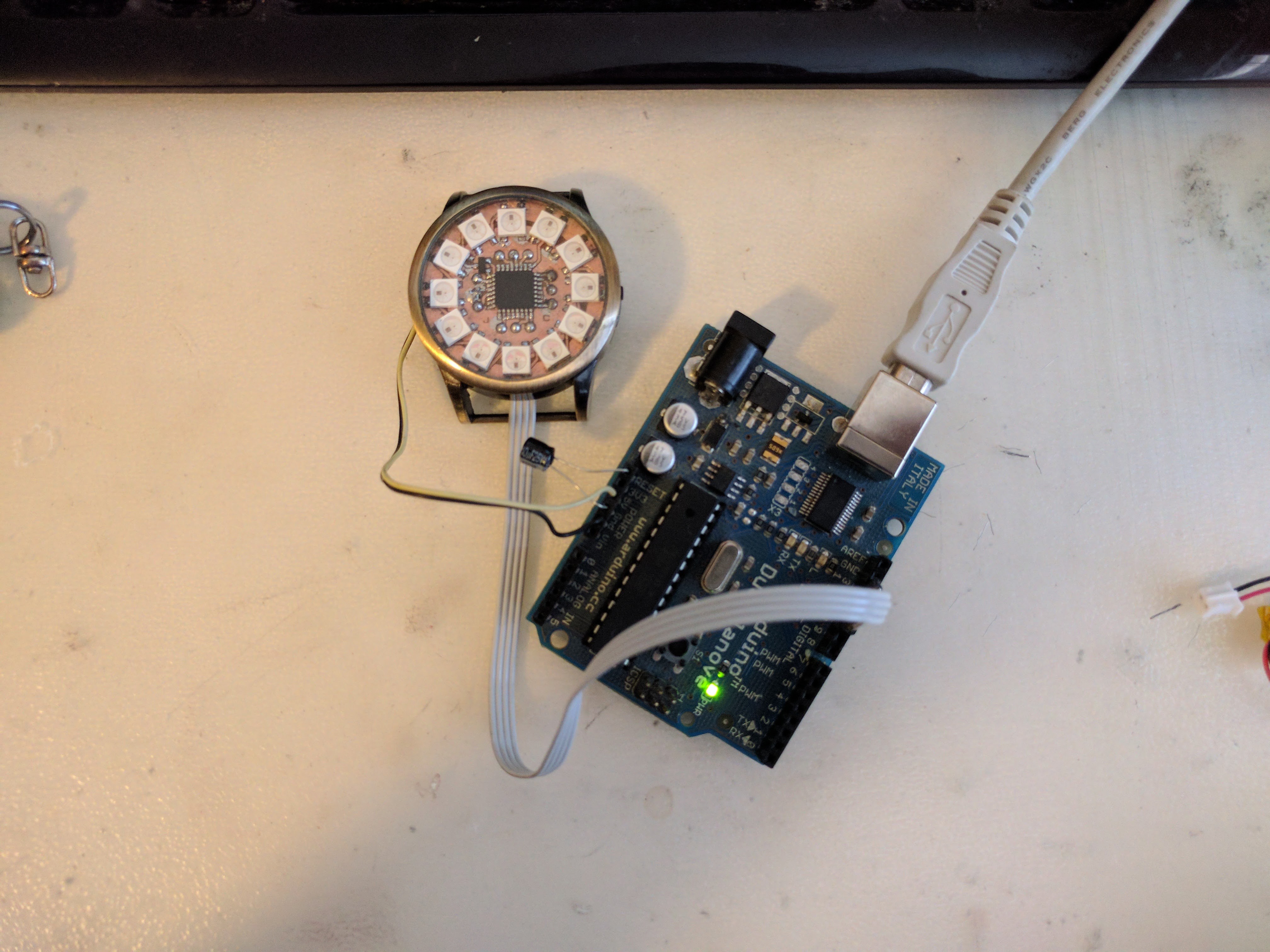
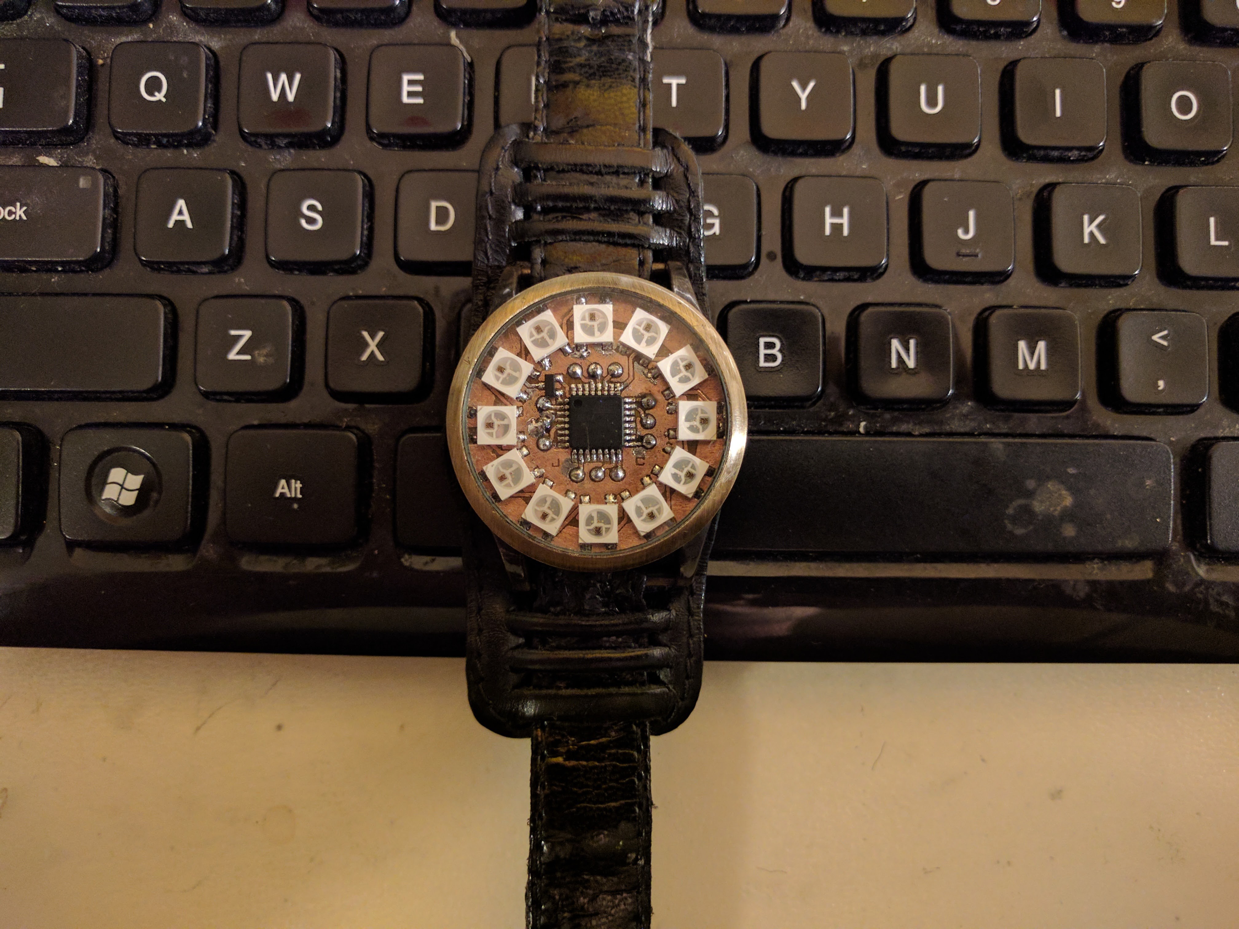
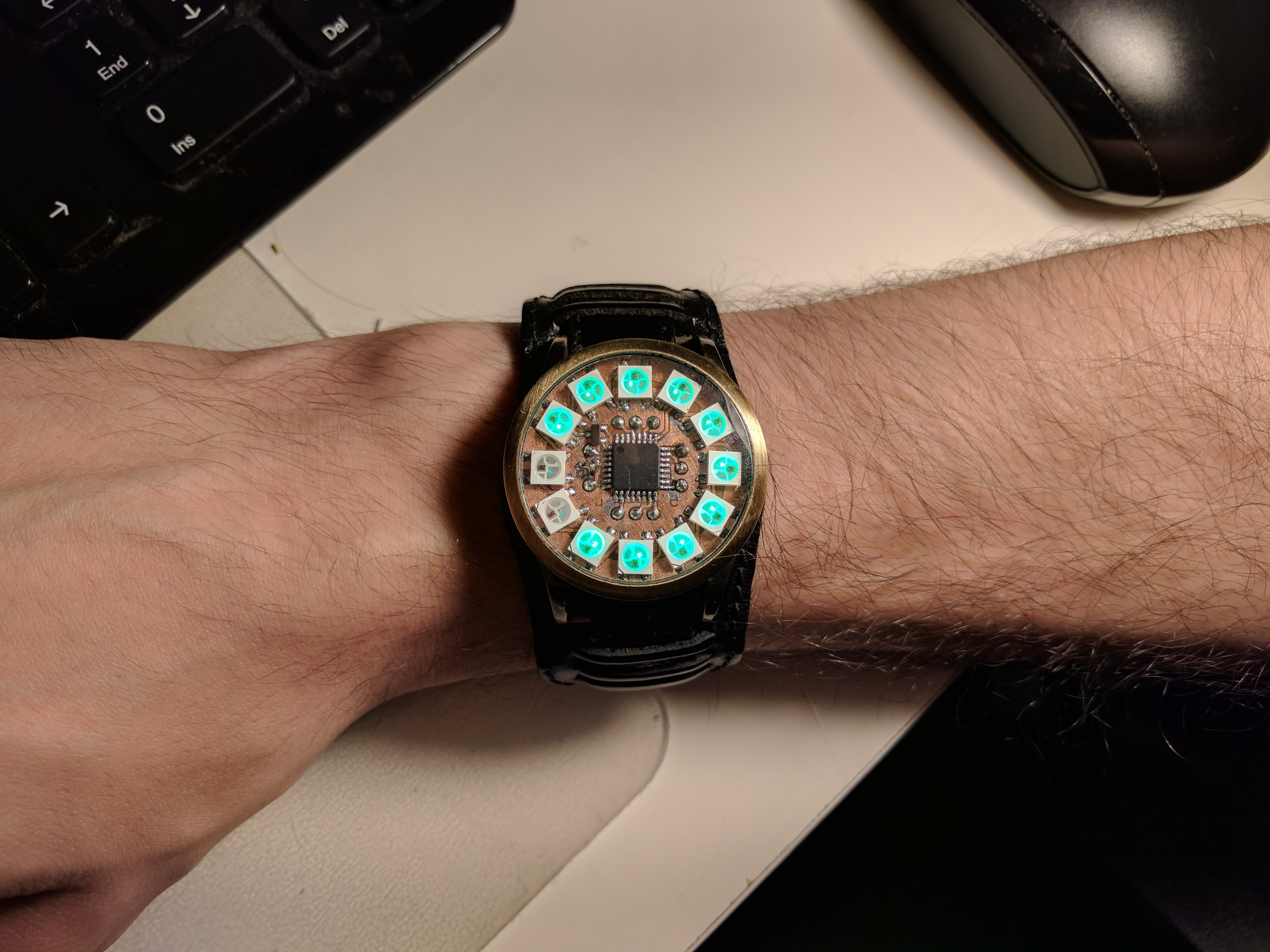
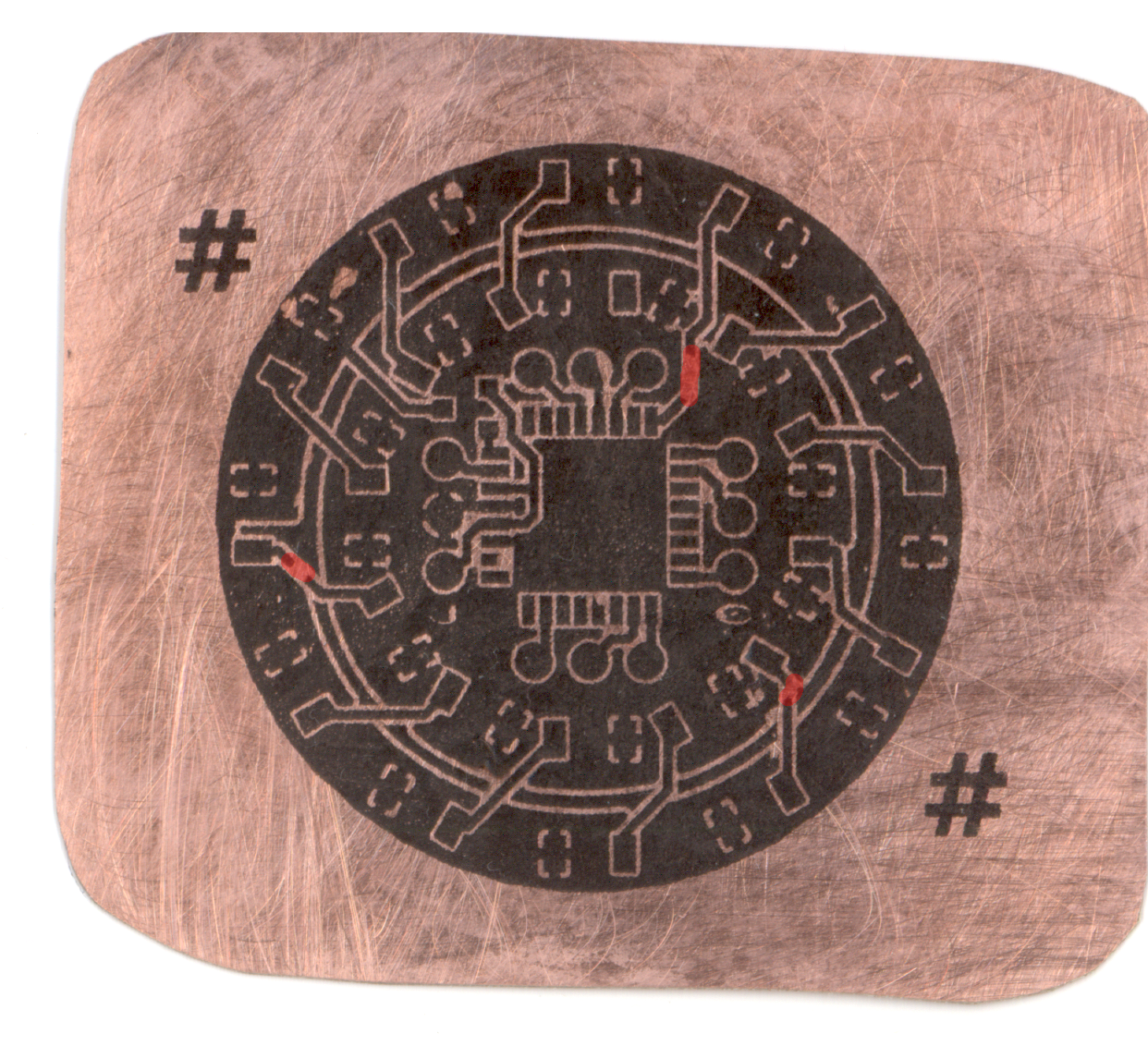
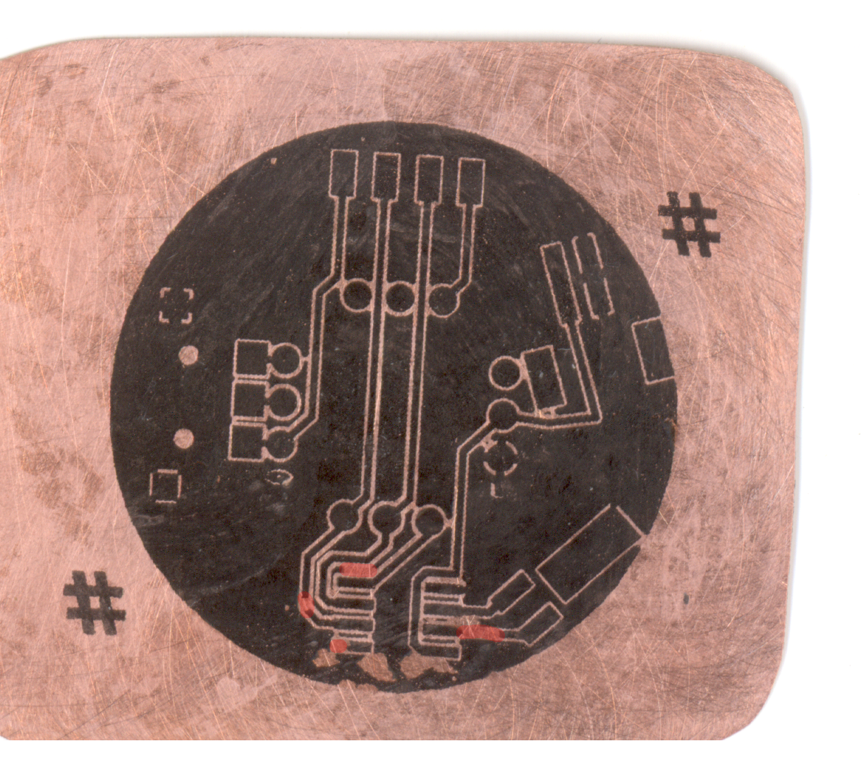
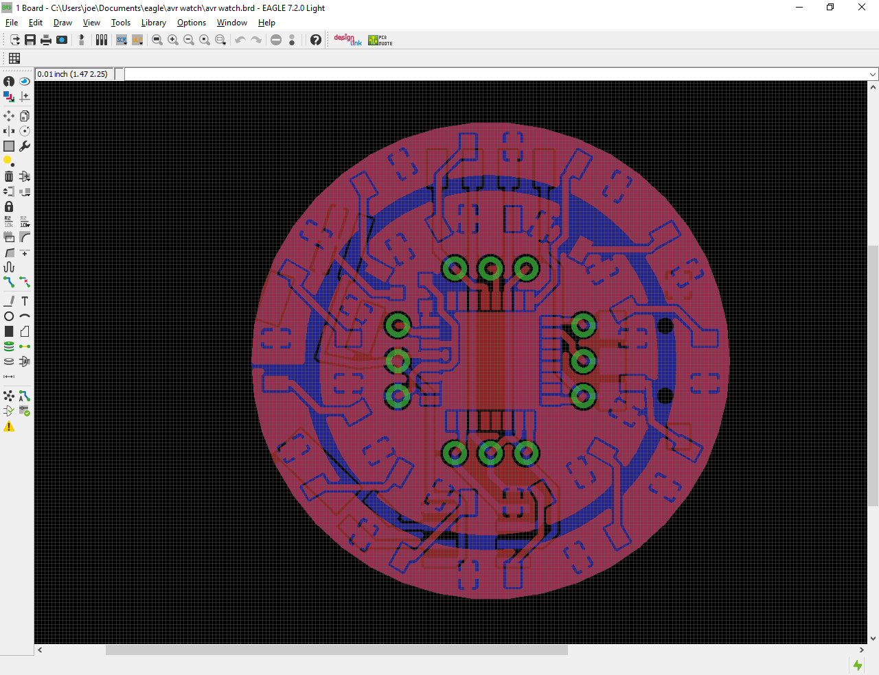
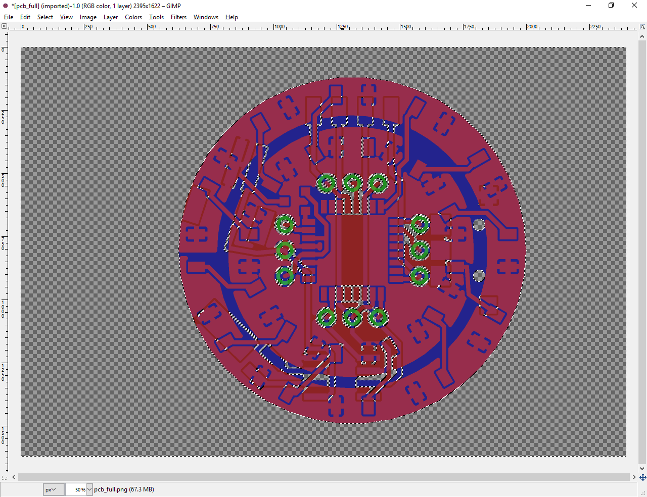
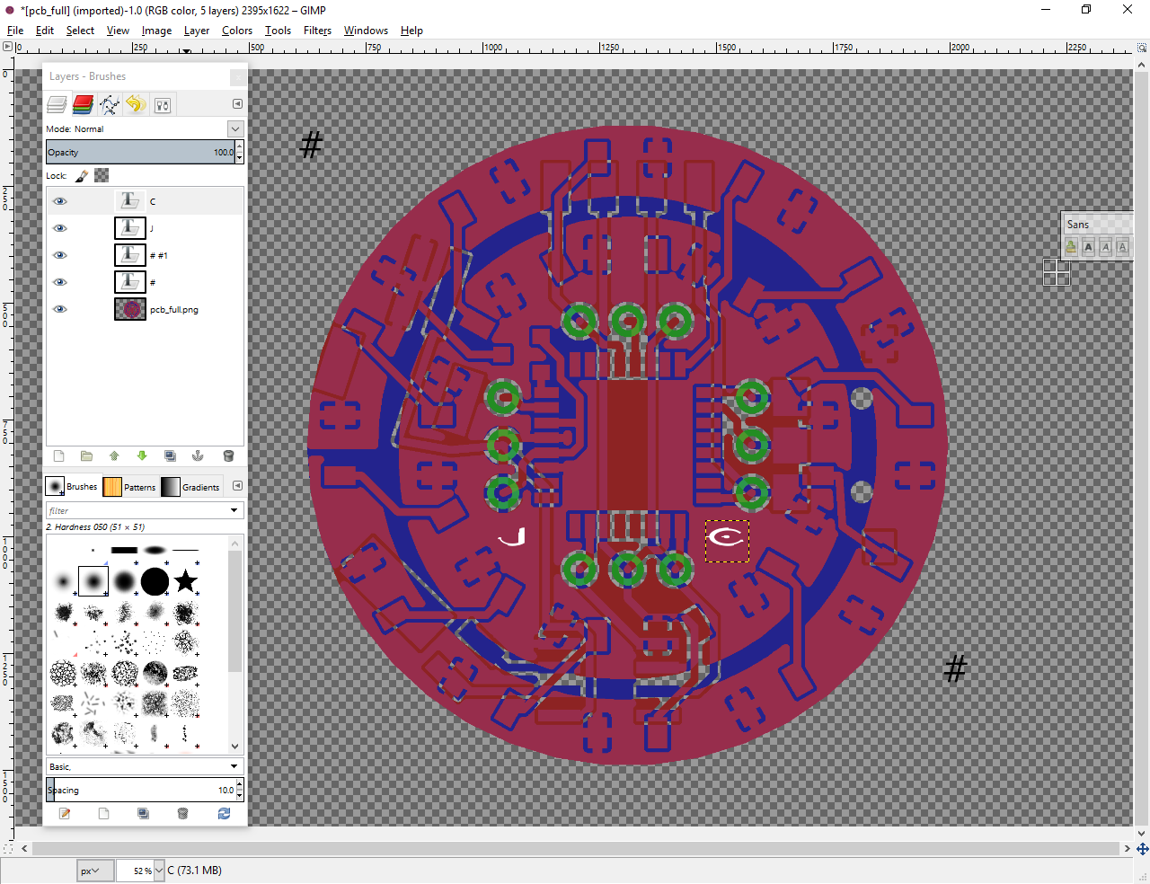
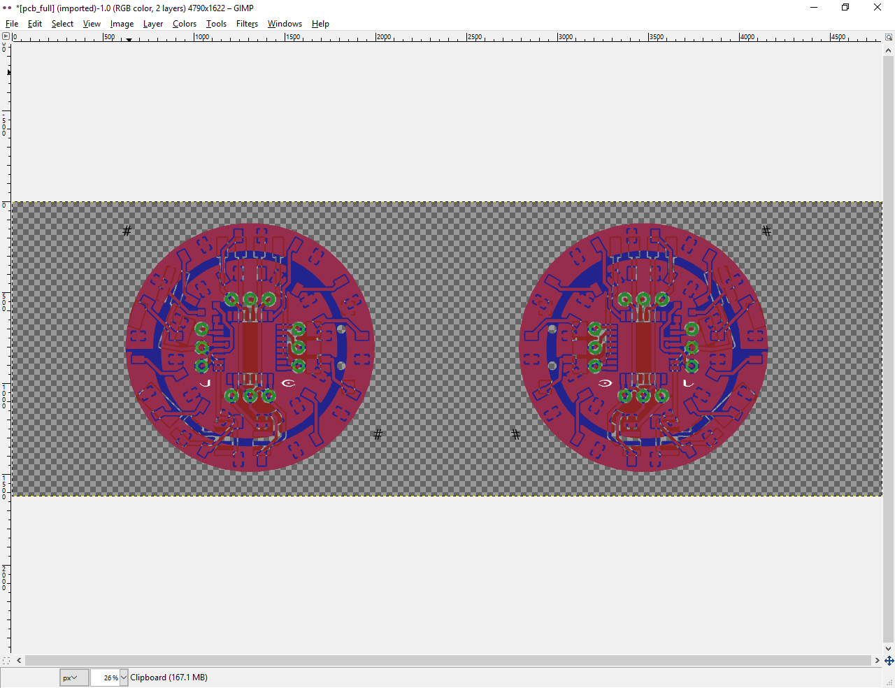
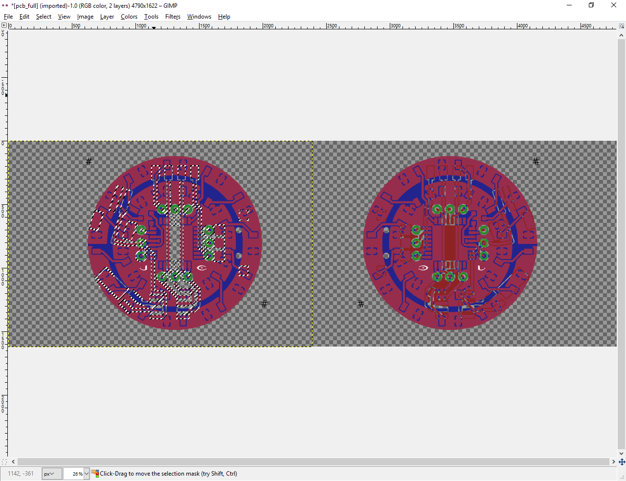
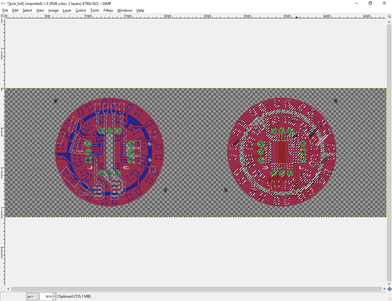
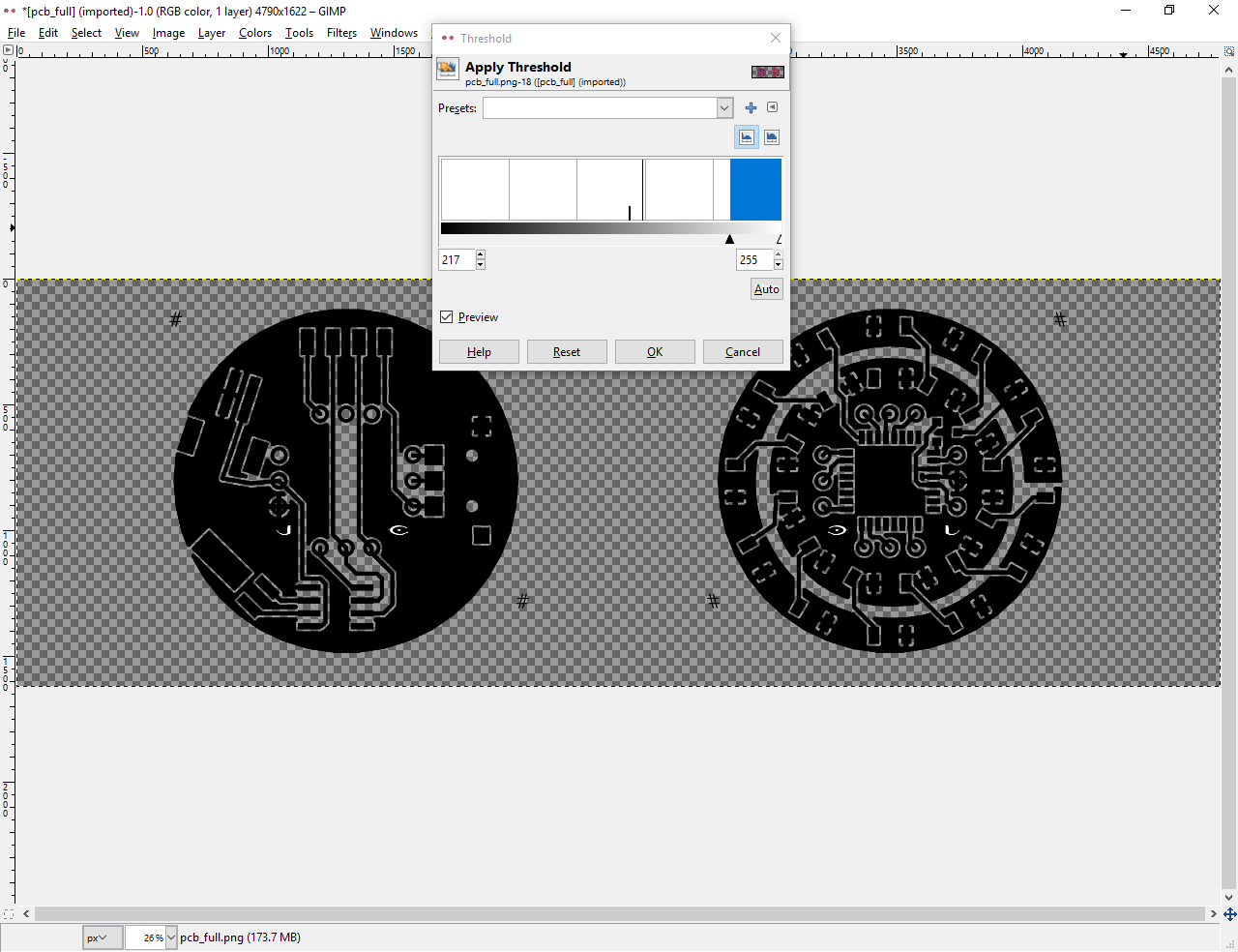
Close
0%
0%

AVR Watch v2

This is the second iteration of my AVR watch

Similar projects worth following
This is a simple wristwatch based on the atmega328p, ds1302 and ws2812 led's. This project aims to document the entire project from cad design to wrist. As I'm a full-time college student with a wife and child to support, updates may be infrequent. I hope to have this complete before I interview for any summer internships.

pcb_full_r3.xcf

PCB artwork, ready for toner transfer (this is the safest to print if you do it from gimp)

xcf - 223.93 kB - 07/25/2017 at 16:03

Download

pcb_full_r3.png

PCB artwork, ready for toner transfer

Portable Network Graphics (PNG) - 41.96 kB - 07/25/2017 at 16:02

Preview
Download

avr watch.sch

Eagle schematic of my watch

sch - 114.42 kB - 02/06/2017 at 05:39

Download

avr watch.brd

Eagle board layout of my watch

brd - 57.37 kB - 02/06/2017 at 05:39

Download

  • 12 × ws2812B addressable leds
  • 1 × Atmega328PU TQFP AKA arduino
  • 1 × DS1302 RTC RTC that works at 2V
  • 1 × 32.768 khz crystal for timekeeping
  • 1 × Selector switch

View all 16 components

  • Redo

    joe5700511/16/2017 at 22:07 0 comments

    The first day of the semester, in disconnecting the battery for charging, my hand slipped and cracked the pcb severing a number of key traces under a few components. I am remanufacturing the pcb and as part of a school project, rewriting the code to be c++ outside the arduino environment. As part of remaking the board, i've made a few traces bigger and also increased the clearence to make pcb etching a little more reliable for this design. Pics of the assembly as well as sourcecode will be uploaded next week. stay tuned.

  • Programming and testing

    joe5700507/25/2017 at 16:43 0 comments

    For this step, i used an arduino dumilanove as a programmer.

    I'll post my code later, as right now it's ugly. I did program this in the arduino environment, but only because i'm lazy. Be sure to burn the proper fuses first. Arduino set the brown out detection at around 4 volts by default. Obviously this will keep your system from working at 3.7-2.9V, that and the BOD drains around 4mA all the time, so you're going to want it completely disabled. 

    I recommend MCUdude's minicore. In arduino preferences, add https://mcudude.github.io/MiniCore/package_MCUdude_MiniCore_index.json to your board manager URLs and install minicore from the board manager.

    His excellent work will allow you to change individual fuse settings very easily. For this, select atmega328, 8mhz internal clock, 328p variant, and BOD disabled. burn the bootloader and then you can program it however you want. You'll probably want a ws2812 and ds1302 library. Don't forget to keep your AVR asleep when not in use, my whole system uses about 40 micro Amps when asleep, and around 90mA when showing the time. If it was awake all the time, my 110mAh battery would last only an hour at best.

  • Etching

    joe5700507/25/2017 at 16:24 0 comments

    For this, you will need first and foremost a clean, open space to work, with easy access to running water. Since i had neither clean, nor open space, i settled for the bathroom.

    Shown is everything needed to etch a board successfully. I used the small beaker to use little acid. My muriatic acid is only 14%, so I used a 50/50 mix of hydrogen peroxide and acid. ALWAYS add the hydrogen peroxide FIRST, then add the acid! Do this in a well ventilated area as it may fizz a little and you do not want to inhale it.

    Use the smallest amount of chemical you can. The amount in the beaker is pretty much ideal. This photo was taken immediately after adding the board and you can already see a faint green hue at the bottom, that is the copper oxidizing and dissolving in the acid.

    This was taken about 30 seconds in. If your mix is good, it will work fast.

    At about two minutes you may see the edges eaten through first. My board has a really thin layer of copper, so your milage may vary.

    After your board is completely etched, remove it from the acid and rinse with water for a few minutes.  While it's rinsing, examine it carefully to make sure there are no obvious shorts. Sometimes, it may be easier to use an engraving tool to fix shorts and to try and add jumper wires where too much was copper was removed. After visual inspection, use a multimeter to find shorts. The multimeter will find any shorts your eyes miss, and this board had a few.

    I was a little excited to build this so i didn't take pictures during soldering, but sparkfun has a terrific tutorial on soldering small packages. 

  • Almost good enough

    joe5700502/13/2017 at 23:15 0 comments

    I just finished my first attempt (for this project) at a toner transfer. I always inspect my boards with my flatbed scanner. I highlighted the unacceptable problems in red.

    As you can see, the errors are small, but in critical spots. This board is a little too small for a sharpie touch-up, larger boards are way more forgiving. Next step, clean the board and try again.

    Once i complete this step satisfactorily, i'll reveal my secret sauce in the instructions.

  • Design

    joe5700502/06/2017 at 05:59 0 comments

    My eagle schematic is a bit sloppy, but I hope it is clear enough to understand the general idea. I'm using the ever popular atmega328p in a less popular tqfp package for the microcontroller, the slightly esoteric ds1302 for timekeeping and the wildly popular ws2812 led for readout.

    This step was a lesson in eagle-fu for me, as I learned how to use a few handy scripts and techniques. Chiefly, the cmd-draw.uld script for creating the circular pattern of led's, and the witchcraft that are ground planes. Sparkfun's tutorials are an excellent resource for learning these. That is, if you wish to continue an unhealthy addiction to a product with inflating prices.

    I also followed sparkfun's tutorial on making new part packages, as my choice of RTC had no surface mount eagle part. If you'd like to cheat, you'll find the library I made attached.

    Next, I'll show you how I prepared my design for printing and toner transfer... After my homework is finished.

View all 5 project logs

  • 1
    Step 1

    Here I will show you how I prepared my layout file for toner transfer.

    This is fairly easy, but not particularly straightforward.

    Starting with your completed board layout in eagle, click the display layers icon.

    When the icon pops up, it should look something like this:

    click None, then select only top, bottom, pads and vias.

    Your overview will now look like this:

    Once you have this view, it's time to export an image.

    Click file > export > image

    Set the resolution arbitrarily high. I use somewhere around 1024. Be sure to check window, as that will save space. DO NOT check monochrome! Save the image, and exit eagle.

    Open the image in gimp.

    1. add an alpha channel by clicking Layer > Transparency > Add alpha channel
    2. Use the color select tool to select all black, then press delete

    3. Now select None. Our goal is to print out one sheet and fold it in half, align the layers, then crease, so we can just slide our blank board in for toner transfer. So to do this, we'll need some way of aligning the layers. For this we will add guides on each end. these can be simple X's or something more elaborate, as long as there is one on each layer in the same position. For this i'm using a pair of octothorpes.

    Note that in the print version, I edited the design a little and used a larger bold typeface for the alignment octothorpes.

    Also this is a good time to place any symbols or art. I'm just going to use my initials using a halo font. i'm printing them in white so they'll be etched away. (It's good practice to keep as much copper as possible to save etchant, also it's just faster.)

    Next is the convoluted part, separating and flipping the layers.

    4. Merge all the layers down. then resize the canvas to 200% width, 100% height, do not center. Use image > canvas size.

    copy the visible image, using edit > copy visible

    Paste it as a new layer, using edit > paste as > new layer

    In the layers dialog window, select the duplicate layer by clicking it.

    Flip the layer horizontally, using layer > transform > flip horizontally.

    If you zoom out you should see the following:

    the left image will be the bottom layer, the right and backwards image will be the top. Remember in eagle, Red is top, Blue is the bottom, and Green are vias. This will be important.

    4. remove parts not relevant to the layer.

    For the bottom (left) layer you want to remove all solid red, leaving green, blue and purple. to do this, use the color select tool and click a RED area. (first make sure you have the correct layer selected!) press delete to clear the area to transparent.

    Next, select the other layer and do the same for blue.

    5. merge the layers by right clicking the top layer and selecting merge down. Next, switch to monochrome by clicking Colors > threshold. slide the slider to the right until the board turns black. and click ok.

    Now just flatten the image using Image > flatten image.

    6. Final touch-ups. If you want, fill in the vias using the bucket fill.

    If you have a crappy laser printer with dirty scratched drums like mine (tried to print directly to a pcb, didn't work), you can rotate the image 90 degrees.

    7. Export! click file > export As. Select portable document format, give it a name and save it! (don't hit the check marks)

    Don't print yet!

    Next up, preparing the paper for printing.

  • 2
    Step 2

    Preparing your paper:

    First off, you need a laser printer and you need to figure out which side of the paper will get printed on. On my dell mfp 1815, the paper side facing down in the paper tray gets printed on.

    One way to figure this out is to just write on one side and print something to see which side comes out.

    At this point, it's a good idea to do a test print and see if its scaled properly by just placing components on the paper.

    If it fits well enough, the real secret to my success in toner transfer is stick glue.

    wearing gloves (keep your greasy meatbag fingers off!), put a clean paper, untouched by meatbag hands, over your test print so you can see the print through the paper.

    Put an even layer of stick glue over it and let it dry. do not put a thick layer on as it will moisten and warp the paper. let it dry, then repeat maybe twice. you want the area completely covered in a layer of glue.

    your mileage will vary depending on glue brand. I've tried elmer's and others, but the best brand i've tried is the cheap crazart purple disappearing school glue stick. the nice thing about the purple is that you can kind of see it as you work. it dries clear though.

    Once it dries and you have your print, cut out the corner with the print. leave enough paper to overlap the entire board. Again, keep your greasy meatflesh off! your bodily oils will interfere with the toner transfer later. Using gloves, and a light source, carefully fold the print over itself, using your printed alignment aids. once you have it aligned, carefully crease the paper.

    Set this aside. While you still have gloves on, you might as well clean your PCB. Using a fine grit sandpaper (or one of my wife's brillo pads), sand the pcb until it's shiny, then sand a bit more. After that, clean it with isopropyl alcohol. it MUST be isopropyl, NOT rubbing alcohol. if you can almost see your reflection except for the scratches, you're good!

    Next step: Transfer!

View all instructions

Enjoy this project?

Share

Discussions

Similar Projects

Does this project spark your interest?

Become a member to follow this project and never miss any updates