 Tron9000
The Plan
The aim is to assemble my old DSO138 scope into a 3D printed housing, with a power supply and use it primarily as a portable/automotive scope.
The housing was on thingiverse - so many thanks to salvation76 for that!
The supply should be able to meet the input requirements of the scope, which is nominally 9V. The battery supply should last for a while. 9V PP3 cells aren't up to the task (100mAh), AA are equally as weak and would need loads to get a semsible voltage, plus I don't want to keep dismantelling it all the time to change the batteries.
So I plan to use 2x 18650 cells in parallel, bumping the capacity up. The Cells will be out of my salvaged stock from laptop batteries.
The charging/monitoring will be taken care of by a TP4056 based USB charging module. The 3.7-4.2V battery supply will be boosted up to 9V using a Boost converter.


Its a fairly simple project, and should prove quite useful, especially diagnosing things on cars.
Below is a simplified schematic of the circuit layout, demonstrating the simplicity:
Building the Battery Pack
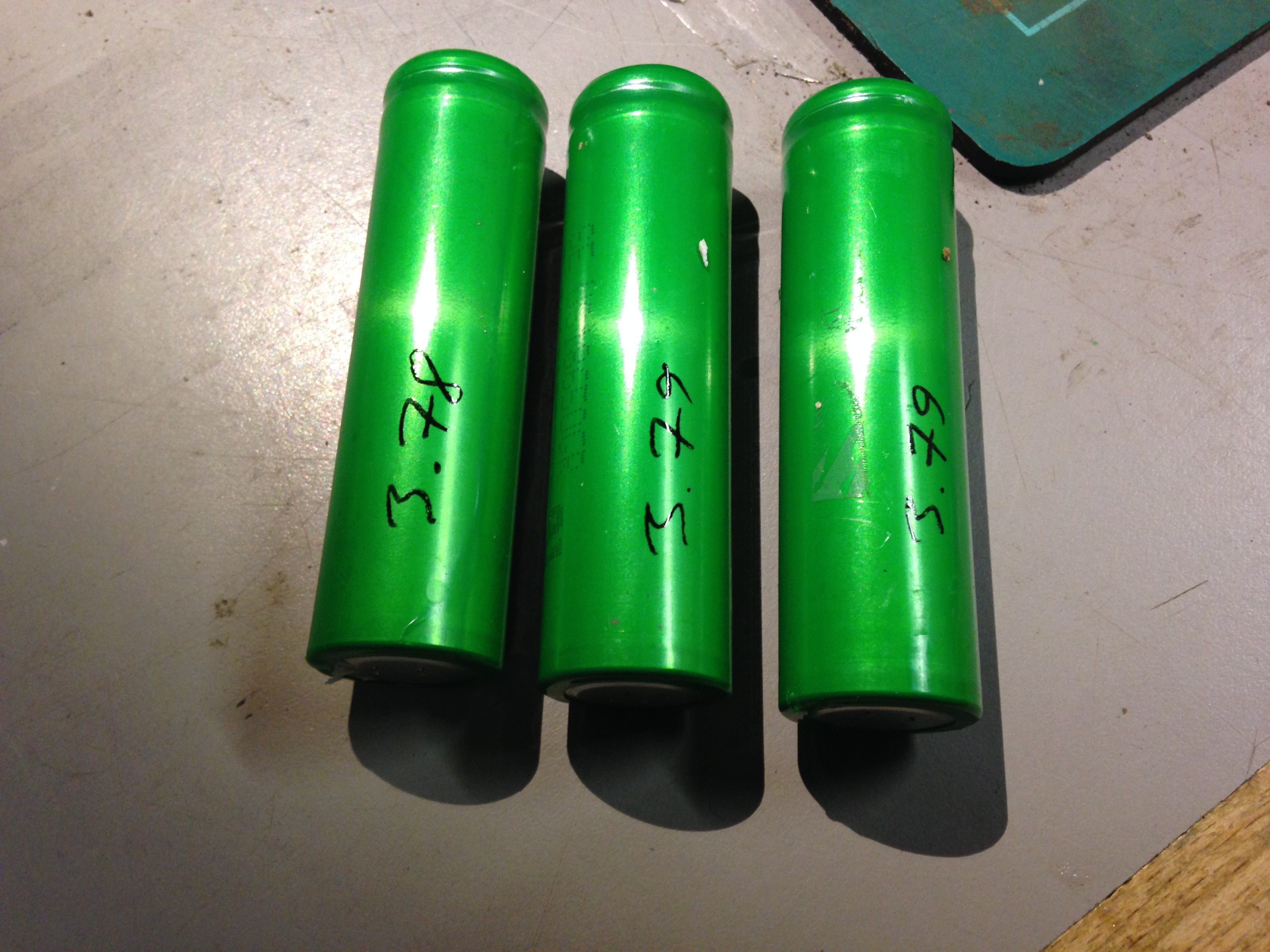
 Firstly I sourced some suitable batteries from my stock of 18650's I'd collected and found 4 that were round about the same voltage.

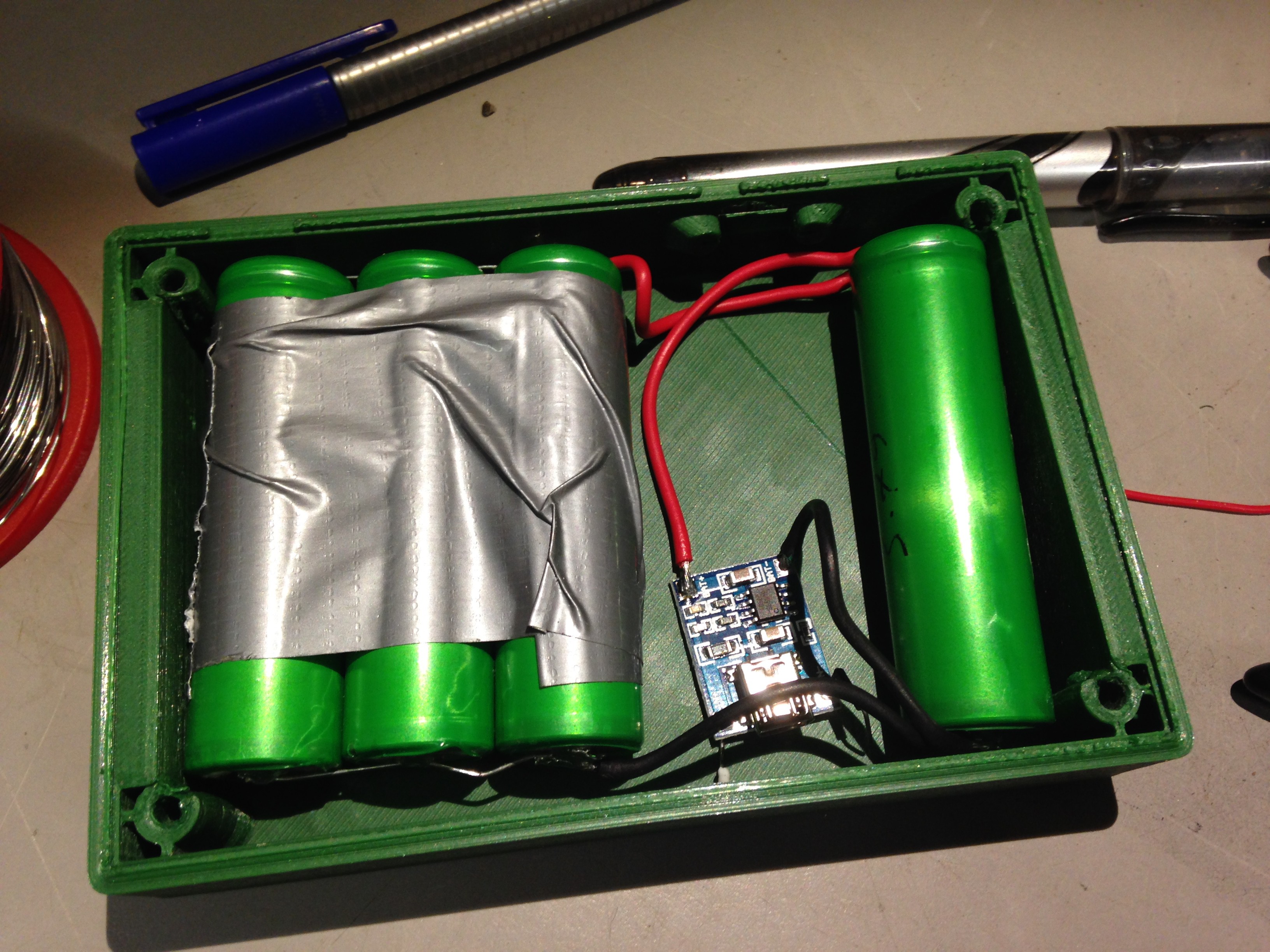
Considering I only needed 2 I thought why not see if I can fit 4 cells in parallel inside the case...

...which they seemed to fit nicely in this configuration. Construction on the pack began based on this layout by carefully soldering some tinned wire onto the battery contacts.

3 of 4 cells soldered together. Got to have duct tape somewhere in your project! the final cell was solder to the other 3 with some heavy-ish gauge wire.
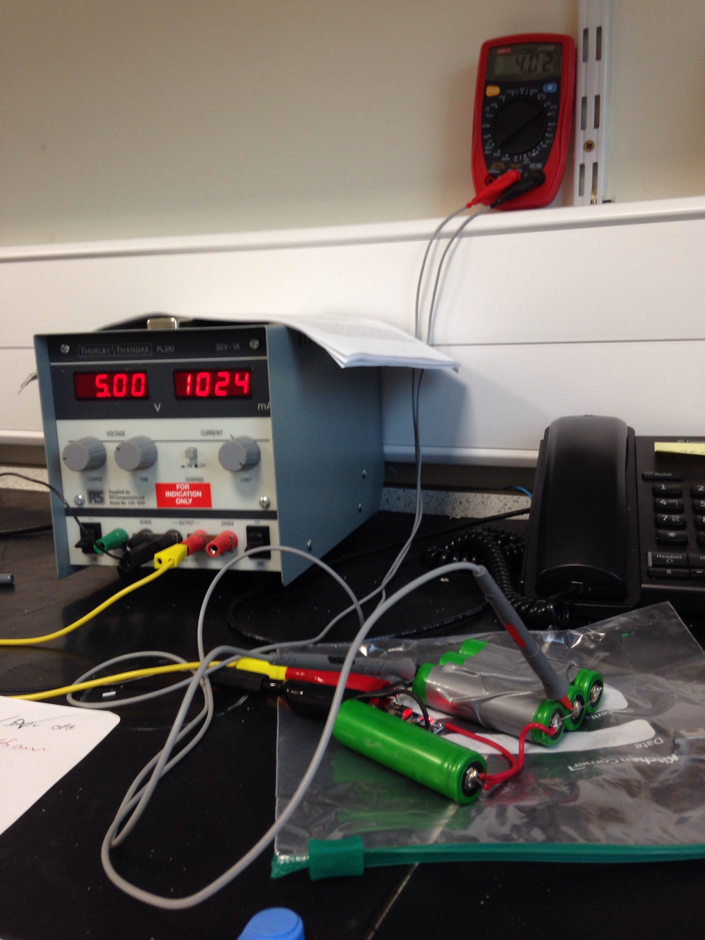
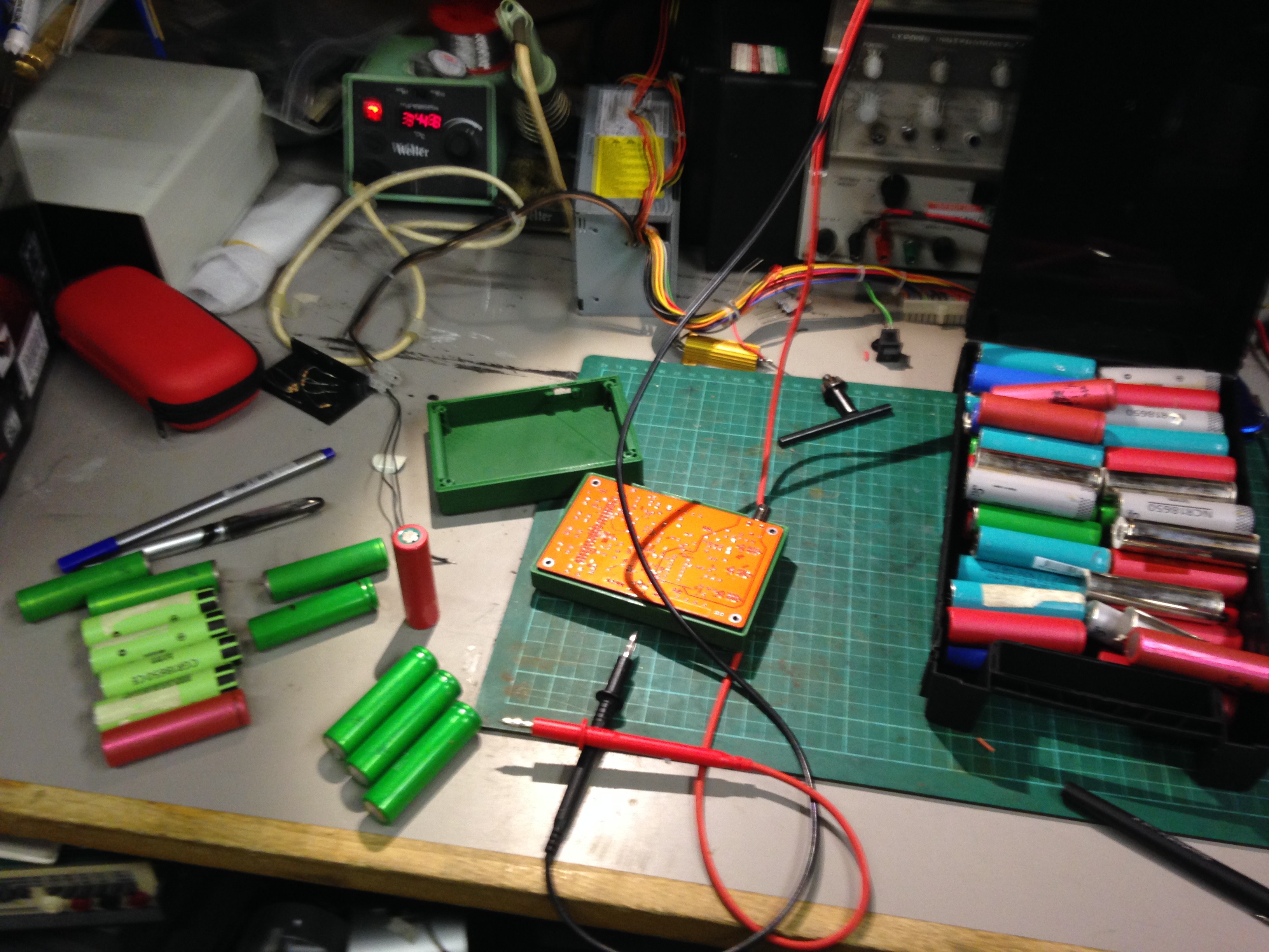
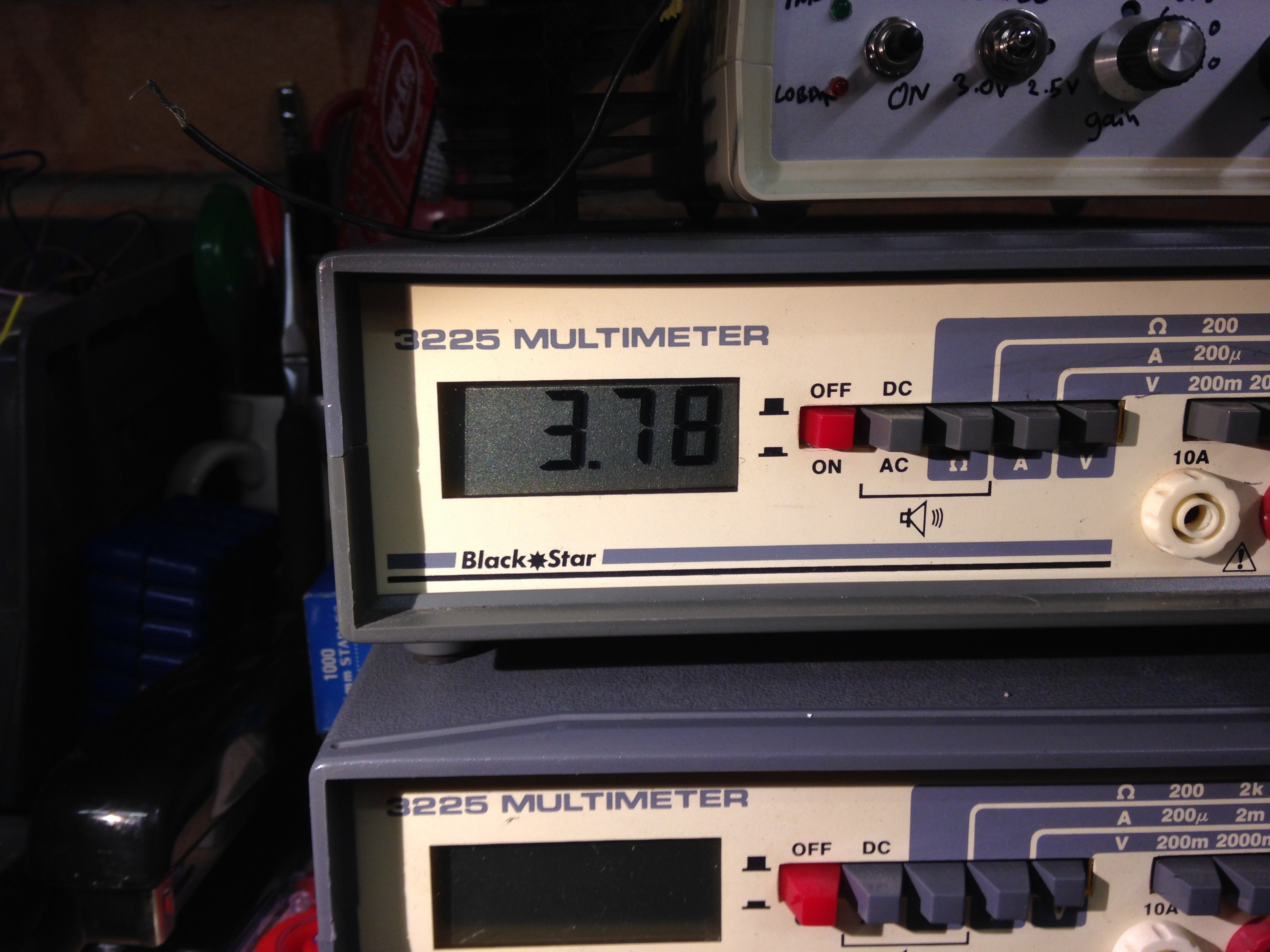
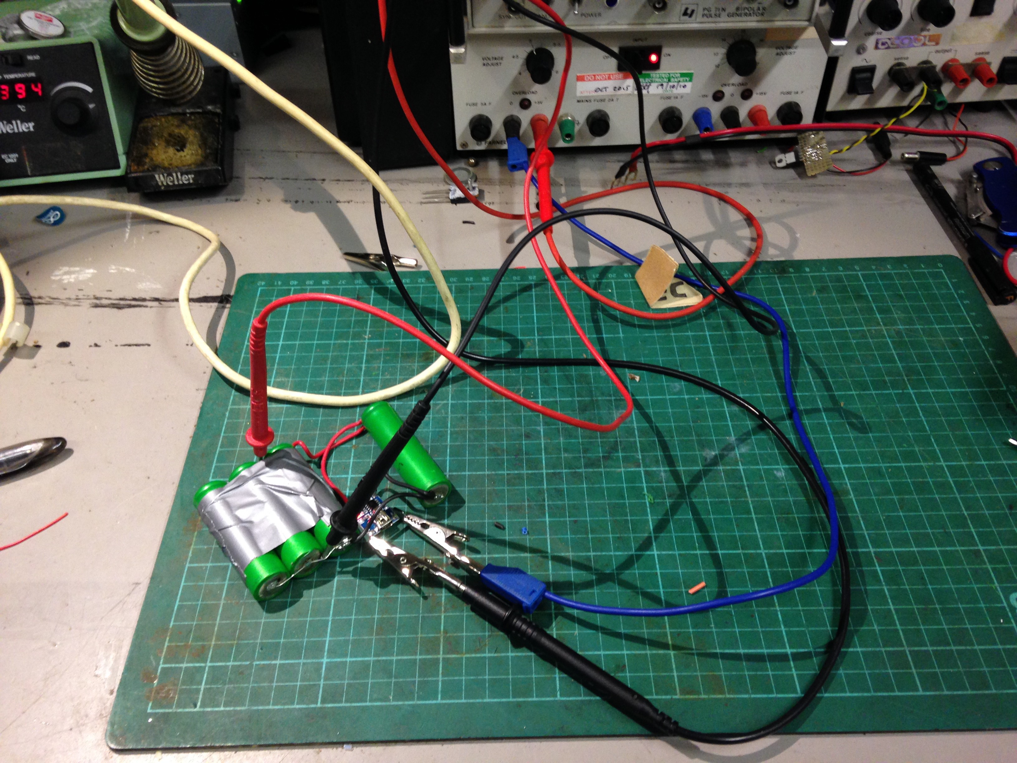
With the pack assembled, it was time to test if the TP4056 board did what it was supposed to


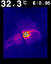
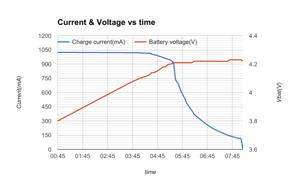
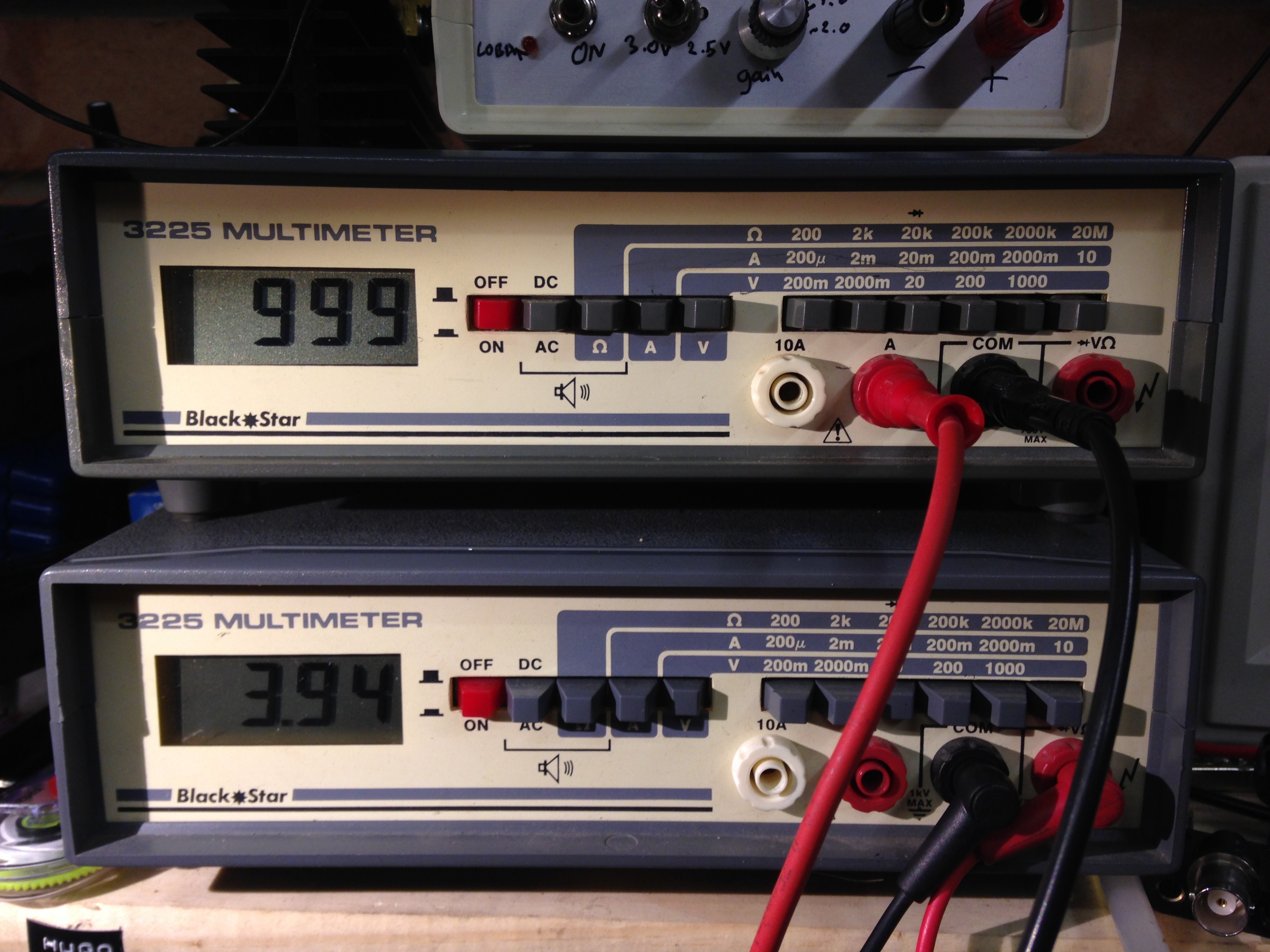
Top meter is current from supply to TP4056 board, bottom one is battery voltage, this seems to be working, but a more lengthy test was needed to determine proper operation. Ideally this charger in this application should provide a constant current up to a battery voltage of ~4.0V and then change mode and allow to charge further to ~4.2V. So the pack was left to charge over a period whilst I monitored it and took readings at random intervals, to obtain the graph below.
As expected the battery had a constant current of ~1A up to a voltage of ~4.2V and then current supply slowly dropped off over a period of about 2 hours after.
Using the Riemann Approximation of integration on the current curve, I determined from the data that my pack had a capacity of approx. 5500mAh (although this was not taking any residual charge left in the batteries into account)
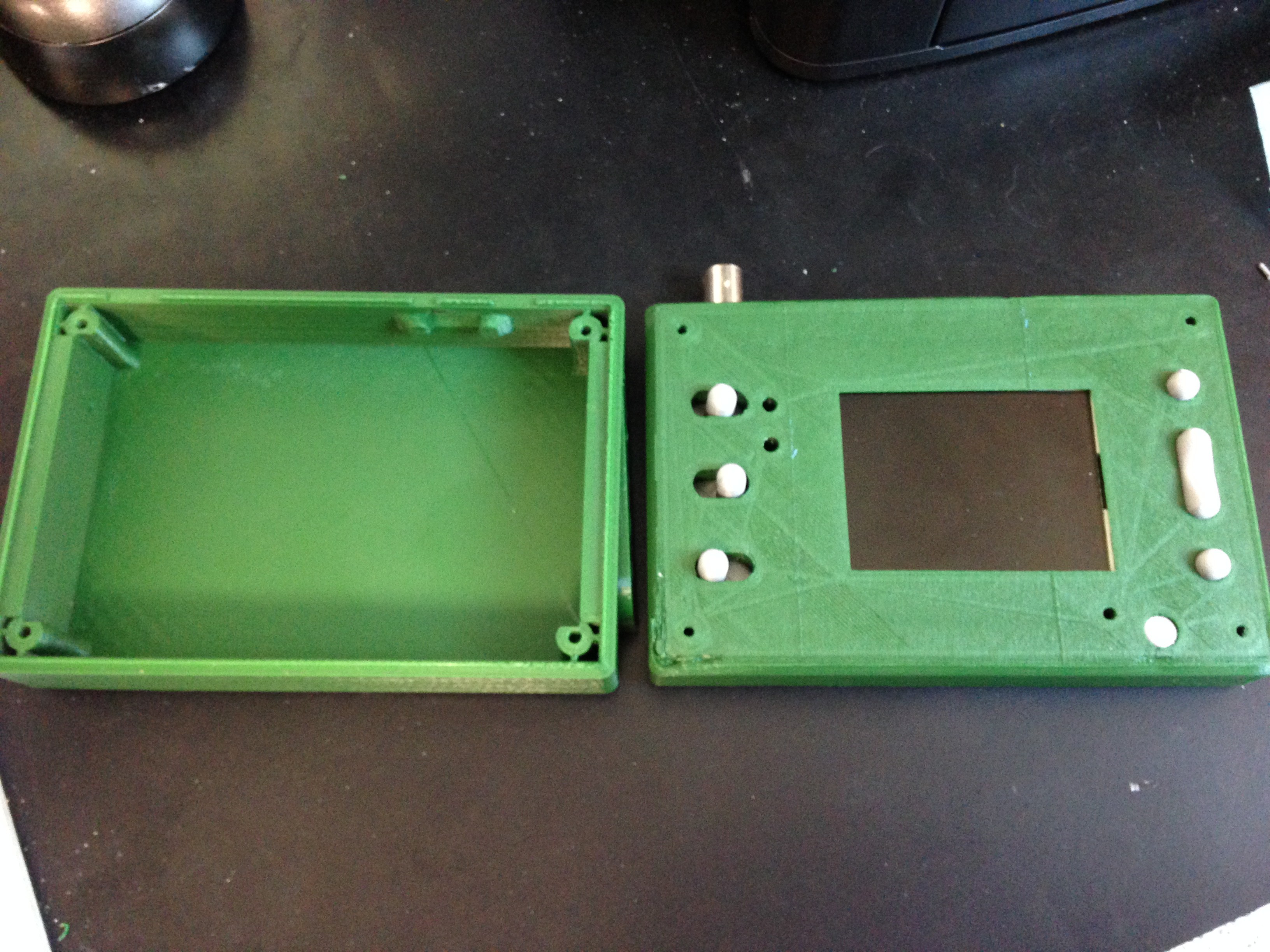
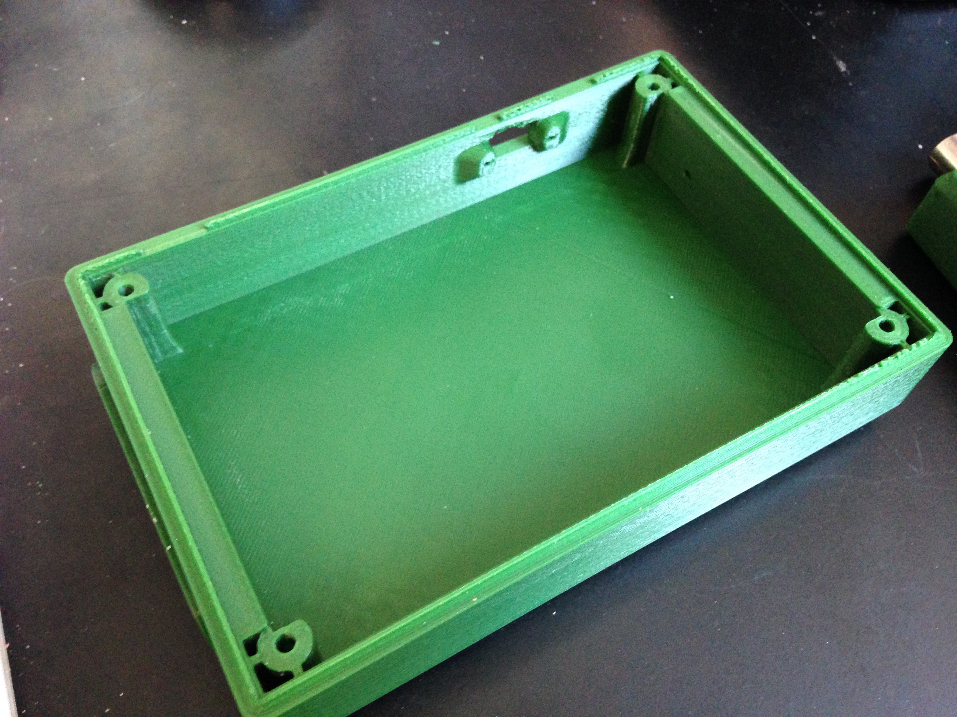
Proceeding with Assembly
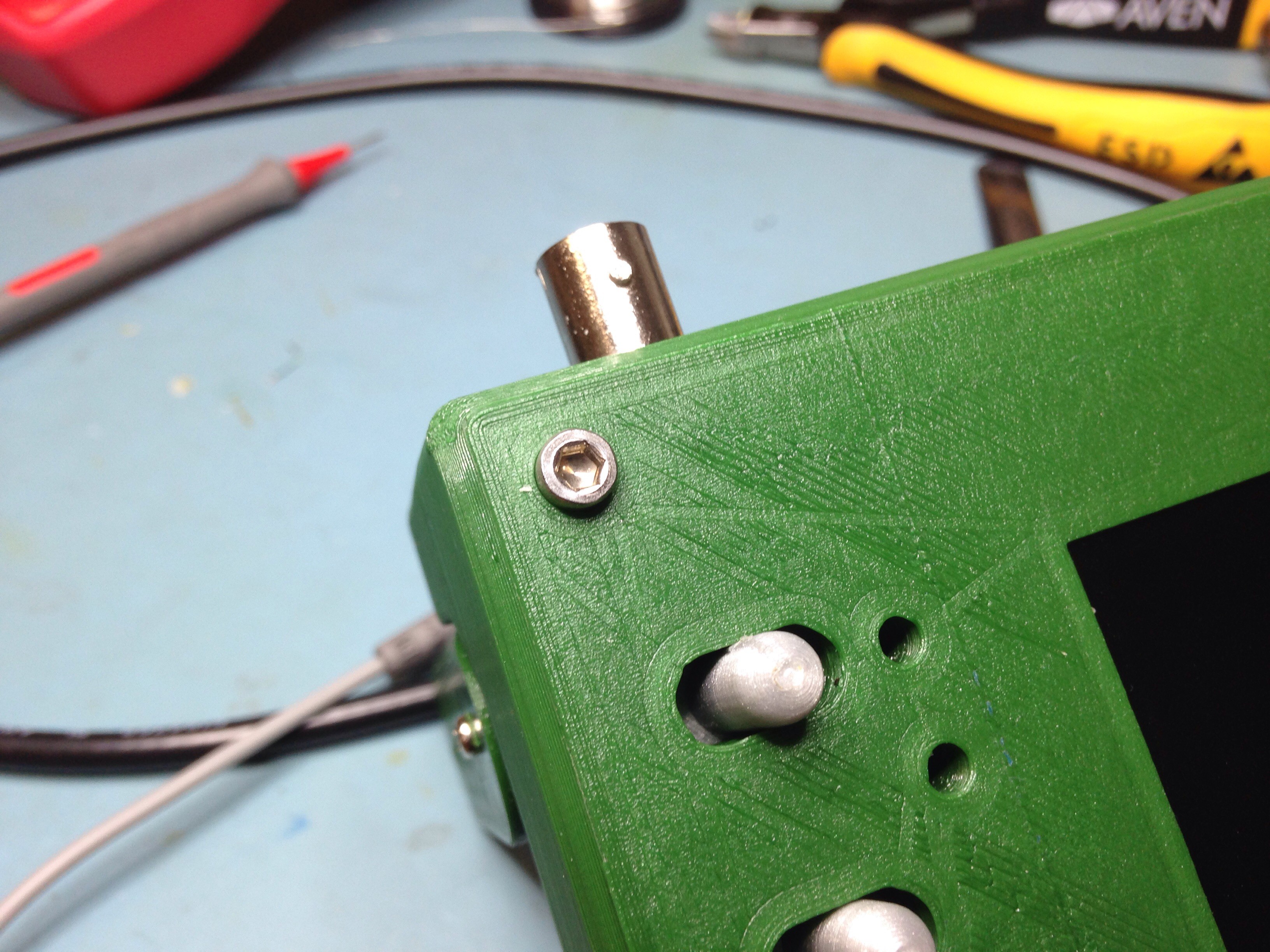
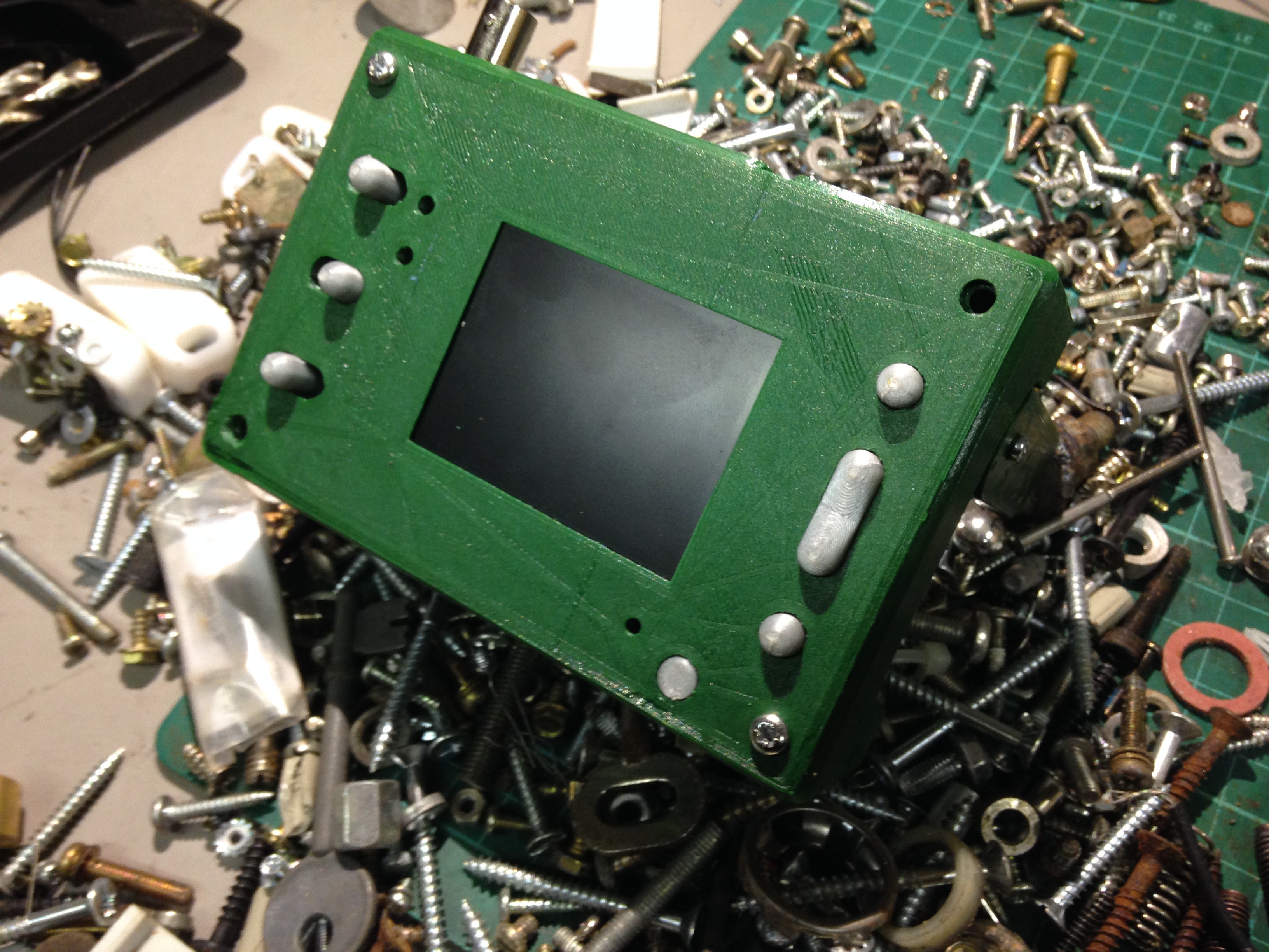
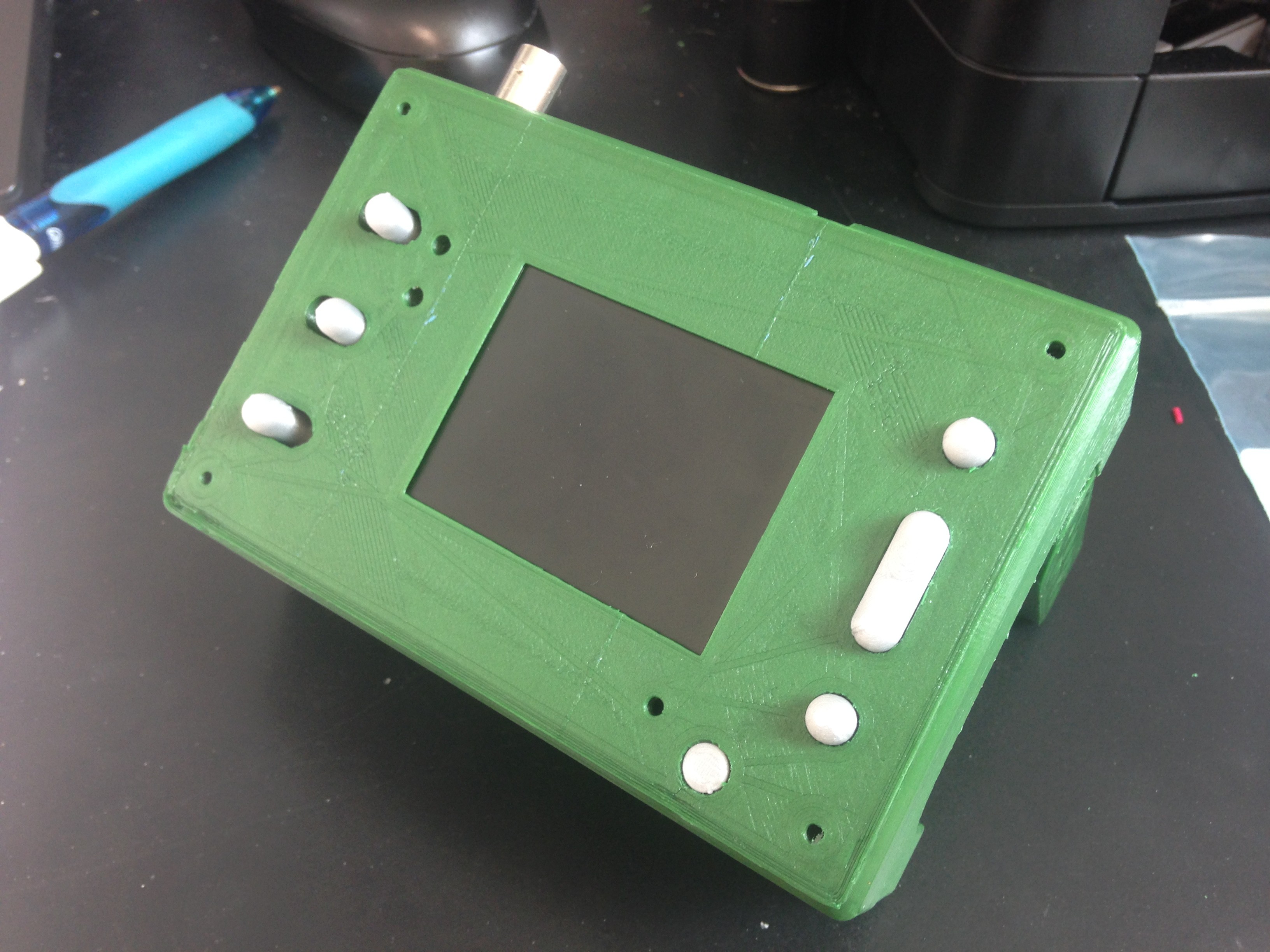
Firstly: offering up the parts to ensure fit:
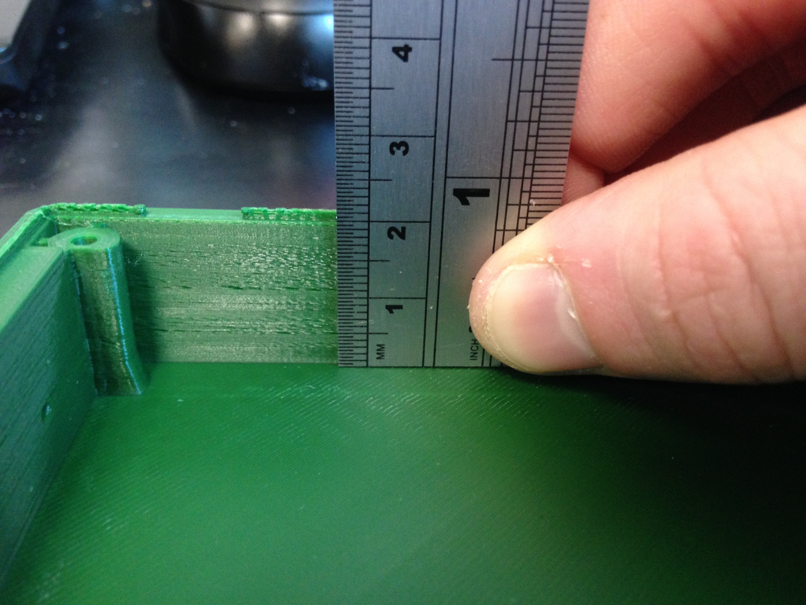
The hole for the switch did require some filing to get it to fit properly. Once fitted and some self tapping screws found, it remained in permanent place.
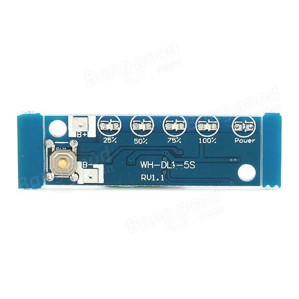
Marking up the PCB's for inside the battery compartment:
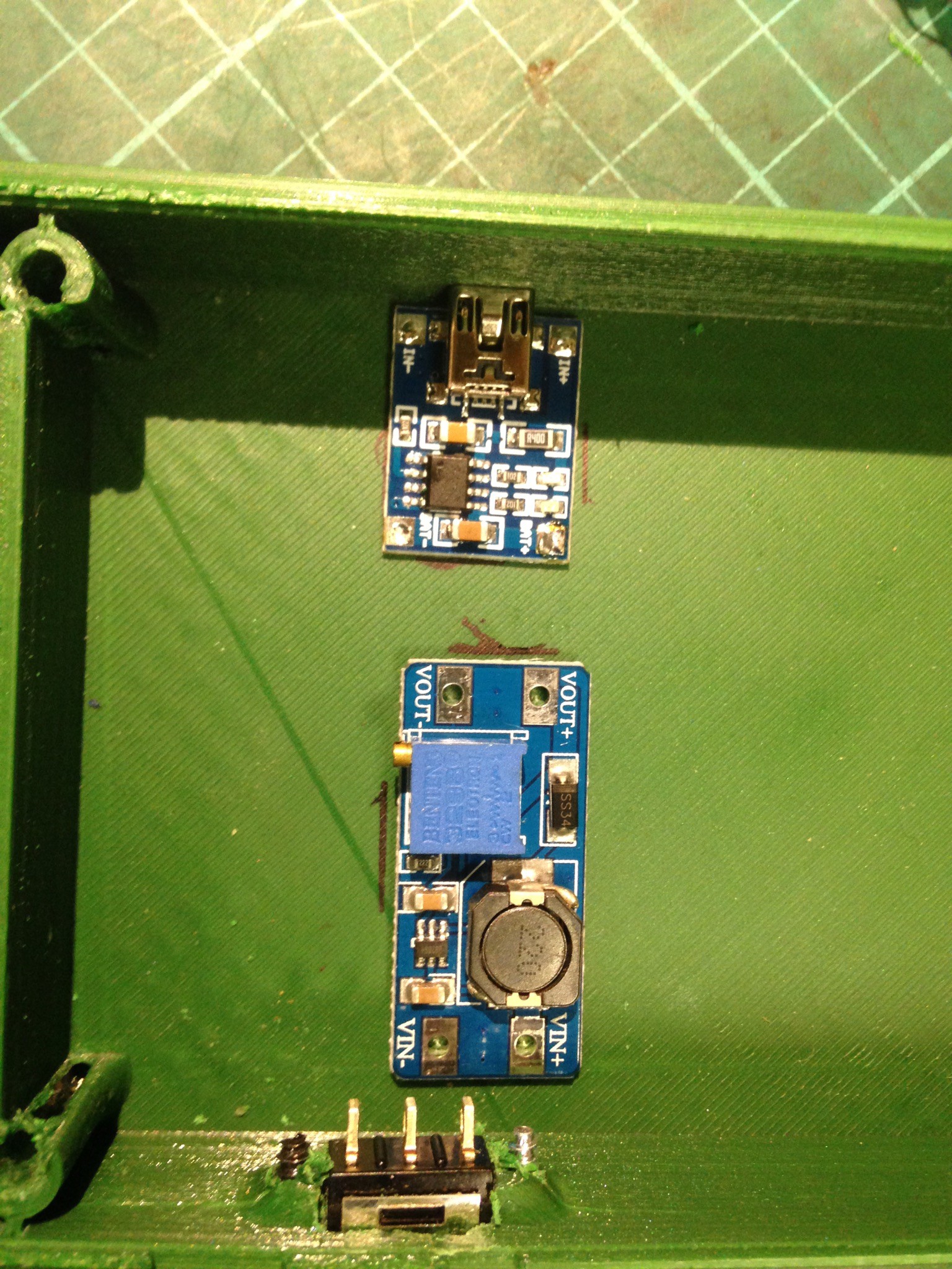
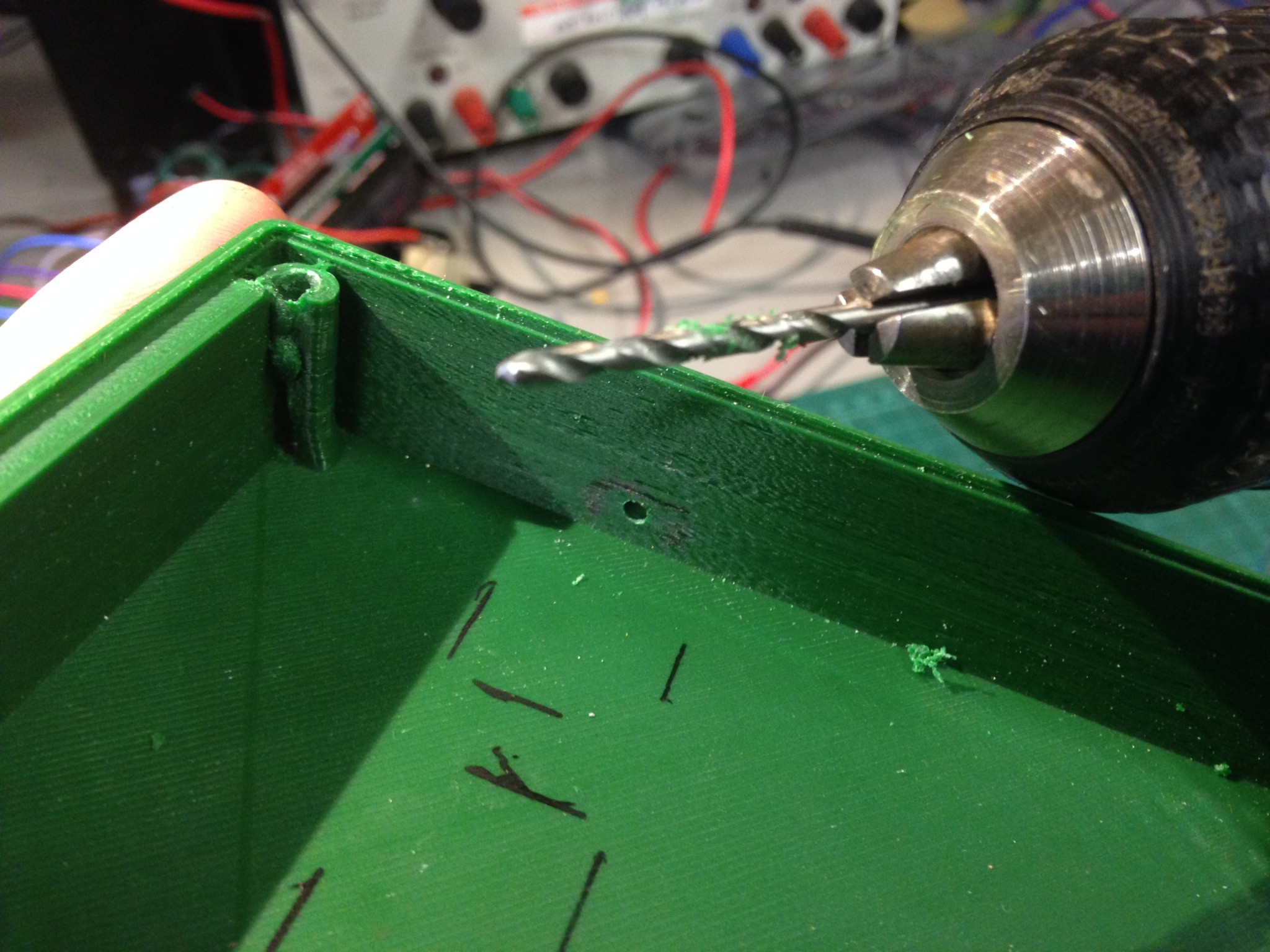
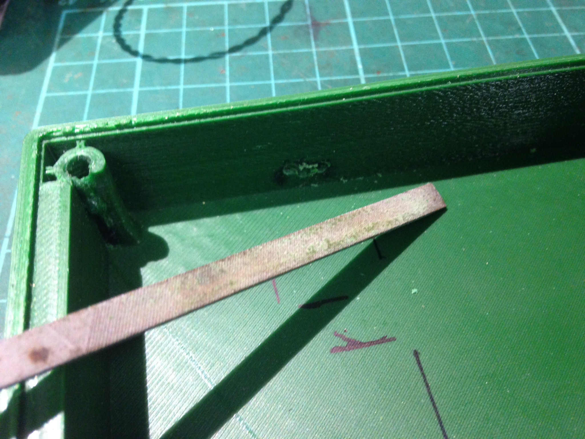
With these in place I was then able to determine roughly where I needed to cut in the side wall to allow the USB connector through to allow charging. This was accomplished using a drill and a file:
Then double checked that the cable could reach through the side wall and mate with the connector:
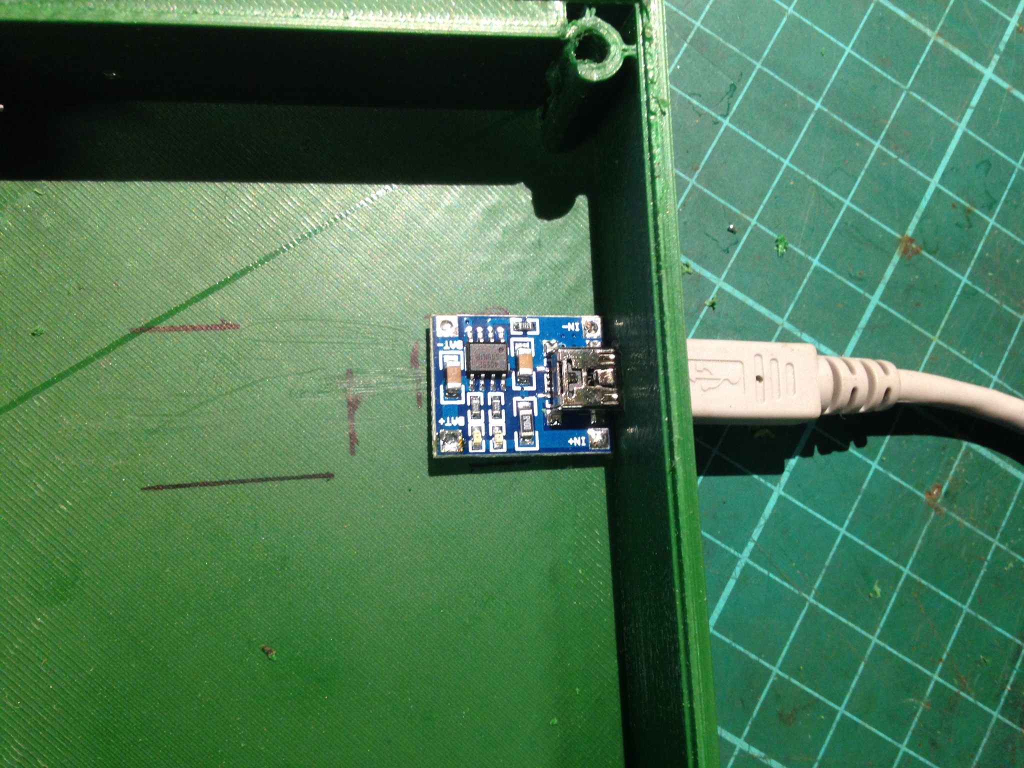
Before making an unholy mess of hot gluing it into place! Pro-tip: glue in place WITH connector fitted stops you from gumming up the USB contacts!
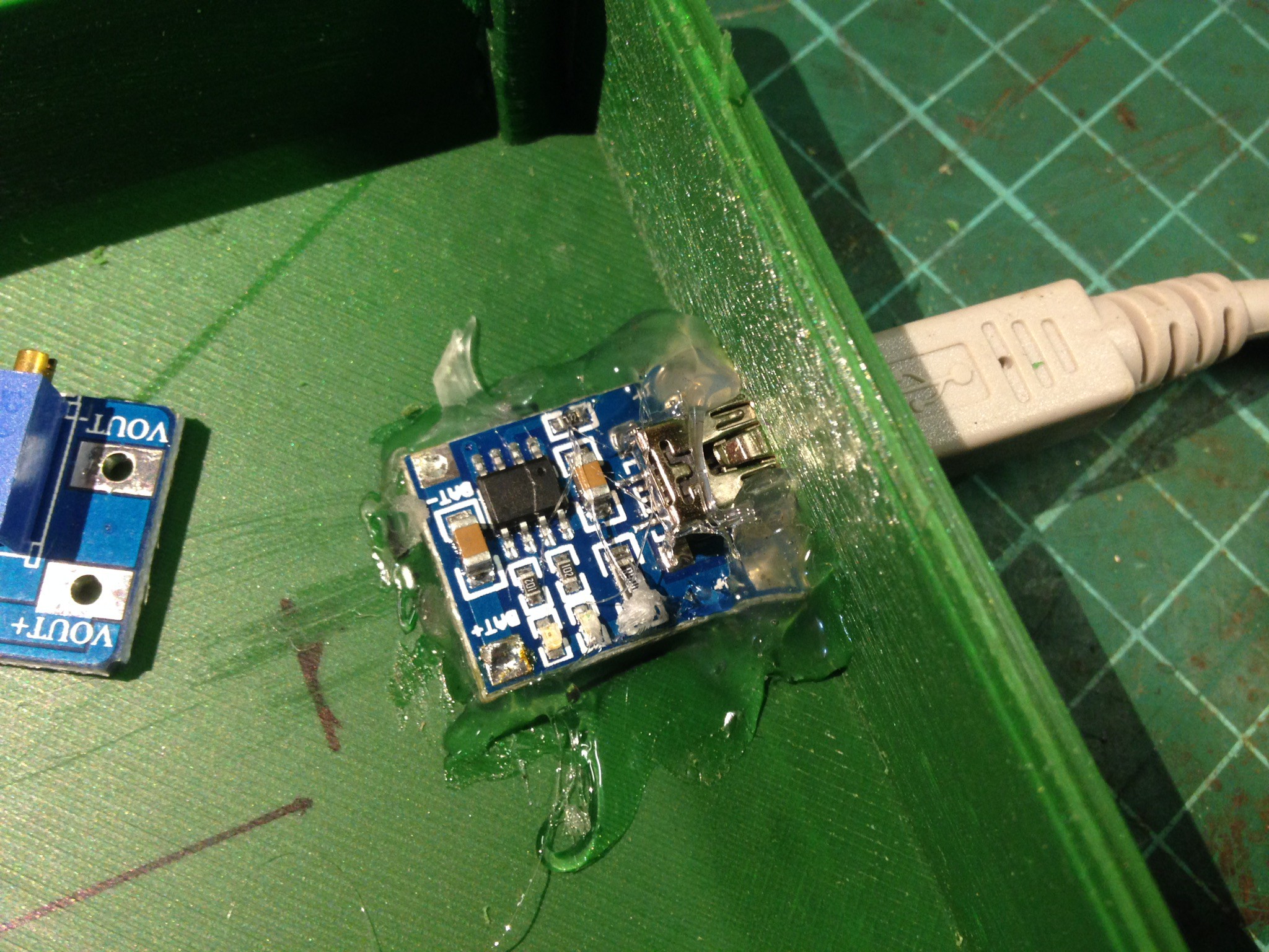
It was at this point I decided to fit some external charge indicating LEDs. But then my phone died and was unable to take photo's. So I noted the direction the surface mount LED's were fitted to the board, removed them, soldered up some wires to a 3mm bulb LED's (one red and one green), drilled some 3mm holes in the side wall just above the charge port, push the LEDs into the holes and hot glued them in place, then soldered the relevant wires of the pads of the charge board.
Before fitting the DCDC boost converter, I powered it up on the bench, loaded it up with a 100mA load in the form of a 50R resistor, and measured and set the output voltage using the trimmer to 5V
I then wired up the battery pack...
Read more »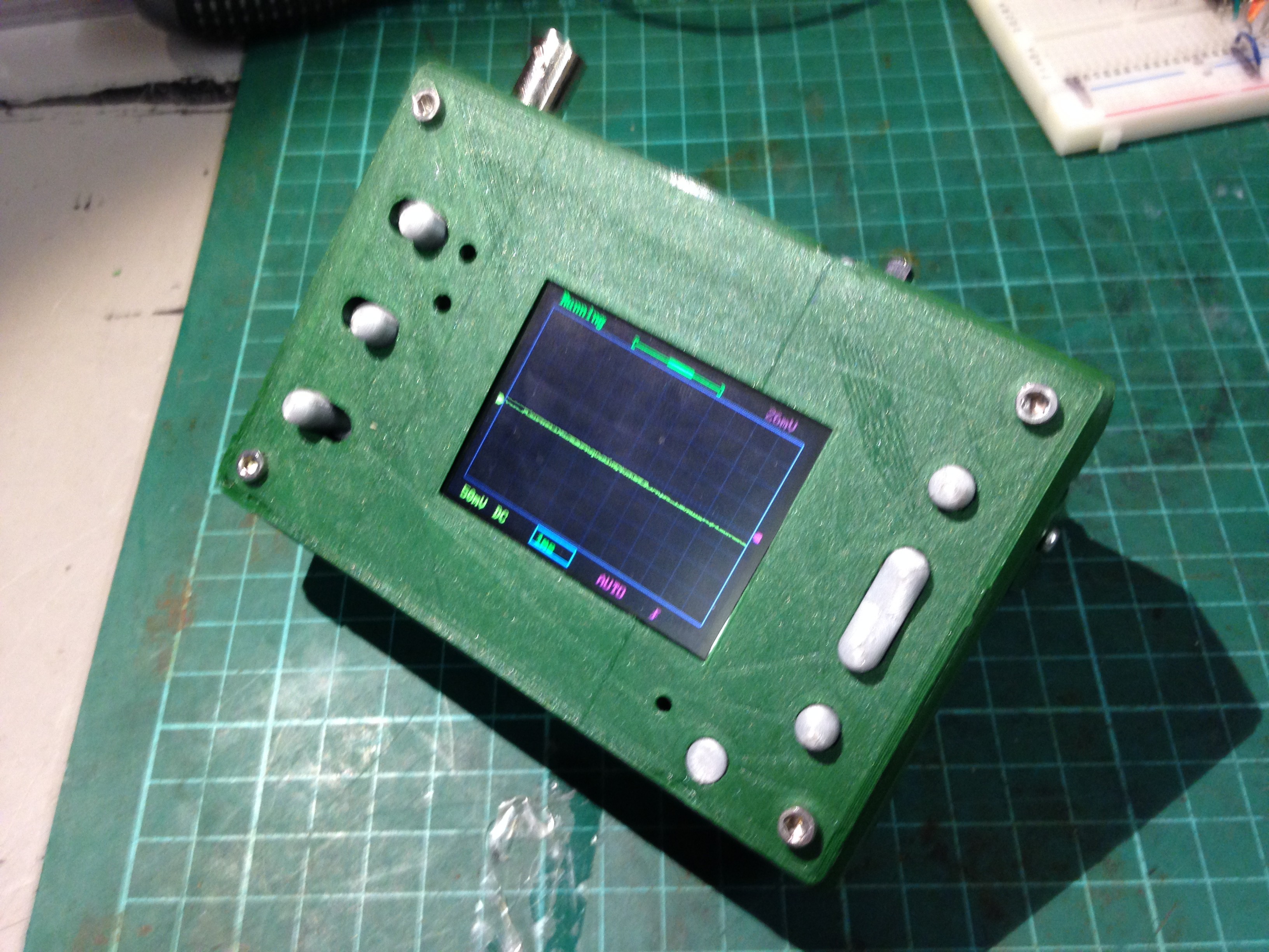


 Hulk
Hulk
 Bud Bennett
 Andrea
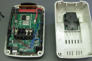
 Quinn
Quinn
I understand that this is an old post. Yet, to new readers - you can skip all that DC boost or buck converting. Just power it with 3 18650 cells.
DSO138 uses LM78L05 inside, in a plastic case. It can dissipate about 0.7W Max current 100mA
When powering with 9V it dissipates 0.1*(9-5)=0.4W
When powering with 3 18650 cells ~ 12.6 it dissipates 0.1*(12.6-5)=0.76W which is a bit over the limit, but the voltage of the cells will drop to 12V fairly quickly.