 Alan Chambers
Intro/background
This project started out with a desire to print, assemble and get working an 'Ada Hand' By Open Bionics in Bristol, an open source designer and manufacturer of prostheses. I don't think I would have embarked on this project unless I had watched this talk and visited them online so have a look here for some inspiration:
These guys have files on their website for a full robotic hand that can be downloaded and printed; this was the initial idea. I like the design because it removes a lot of fiddly mechanical parts/fixings and uses the material properties to achieve the movement.
Initial issues and project redefinition
Having read through the data sheets etc I came across a number of potential issues.
Firstly, the recommended material is called 'Ninjaflex', very cool flexible filament that you should be able to run on most quality printers. From what I gather it has a plastic like quality but is incredibly flexible and hardwearing. I couldn't get hold of this through university channels (which I had to go through if I wanted funding for the project). I could get hold of some flexible rubber filament called 45flex but although they were both flexible, that is where the similarity ends, on paper at least. The Ninjaflex is marketed as being low friction, the 45flex is marketed as a printable rubber (implying higher friction). This could be a problem with actuating cables/ribbons snagging.
Secondly, the 45flex is softer and more elastic so potentially the structural properties of the Ada Palm could be compromised.
With this in mind, and that the palm would need around 26 hours to print, I was not keen to just press on and hope for the best. My experience is that the larger the part, the higher chance of a misprint.
My thoughts at this stage were to convert the stl file for the palm to an stp file, load into solidworks, chop a finger off and do a test print. This didn't happen because of the anatomically correct nature of the palm; it was so geometrically complex that every single computer I tried it on just crashed.
The next step was to install Blender 3D (Open source modelling software used by Open Bionics) and try and amend the model in that. A quick go with blender and I realised this software was totally different to what I was used to, and maybe I would be better improving my Solidworks skills than trying to learn a whole new program.
At this point I abandoned the Ada Hand and decided to design my own hand, it will be heavily inspired by it though. One thing I would like to do is to break it down into smaller parts to mitigate the risk of misprinting a big part. This would also mean that more parts could be made solely from PLA/ABS, reducing print time and complexity.
New goals
Design goals: Design and make a working finger, then a palm, then a thumb, then the rest of the fingers. Primary focus is on mechanical performance, rather than being a coding/electronics exercise.
I had a chat with one of the technicians at uni and found that he had acquired a Makerbot 2X with 2 print heads. This was for printing dissolvable supports but having done some research it may be possible to print with PLA or ABS on one head, and 45flex on the other. I couldn't find anyone who has done this at uni, or online so it's going to be a learning exercise.
The first step will be to do some test prints to see if this can be done. If it can then I intend to design the hand to be printed as one piece, but of two materials. The benefit of this is firstly that I will get the structural properties of the PLA/ABS where I want it, and the flexible, grippy properties of 45flex where I want them (joints, palm and fingertips).
Before I get into the minutae of the design, I think it would be a good idea to work out the manufacturing process.
Combining .stl files
In order to perform a dual extrusion on a 3d printer, there needs to be 2 .stl files merged together on the build plate, the extrusion heads are then each allocated a part before printing. There are a number of ways of doing this of varying complexity, I have chosen what I think is the simplest.
I designed 2 simple parts (a finger joint when combined) then brought them into a soildworks assembly and mated them so their positions were correct, relative to each other. I then created two tabs per part separate from the main model which would be stacked on top of each other, this meant that the base and end planes of each part were the same. The next step was to suppress one part and create a .stl file of the other, for each part:
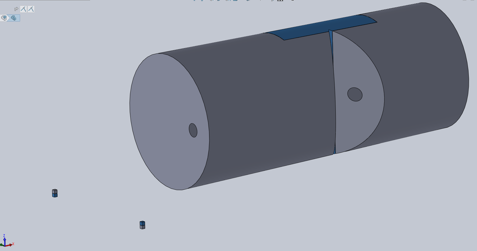
You can see the two tabs in the bottom left of the image, giving the same
datum planes for both parts.
When I loaded them into makerbot they were perfectly aligned on the build platform, meaning I can now go to print (once I have tuned the printer for the flex material).
Printer setup
If you are doing something like this then you are going to need to get your head around the custom print settings menu, and potentially making changes in text editor rather than the makerbot GUI. Do small test prints to start with and watch what happens, make one change at a time unless you are experienced at setting up printers.
It took a few goes to get the printer and the flex45 filament to work, the main issue is that it takes longer than normal for the filament to cure. This can result in the internal supports collapsing if there is not enough infill, particularly if there are small pillars/tabs etc to build. One way around this is to increase the minimum layer duration. The maximum setting on makerbot is 30s, if you want to make it longer then you need to edit the print settings in a text editor (notepad is no good, you will need something like sublime text). There will be a line that looks like this, use a find tool to speed up your search for it:
"minLayerDuration" : 30.0,
Change it to whatever you want, just be warned that it slows down the print speed so that it prints for the whole layer duration, rather than print at the preset speed and wait.
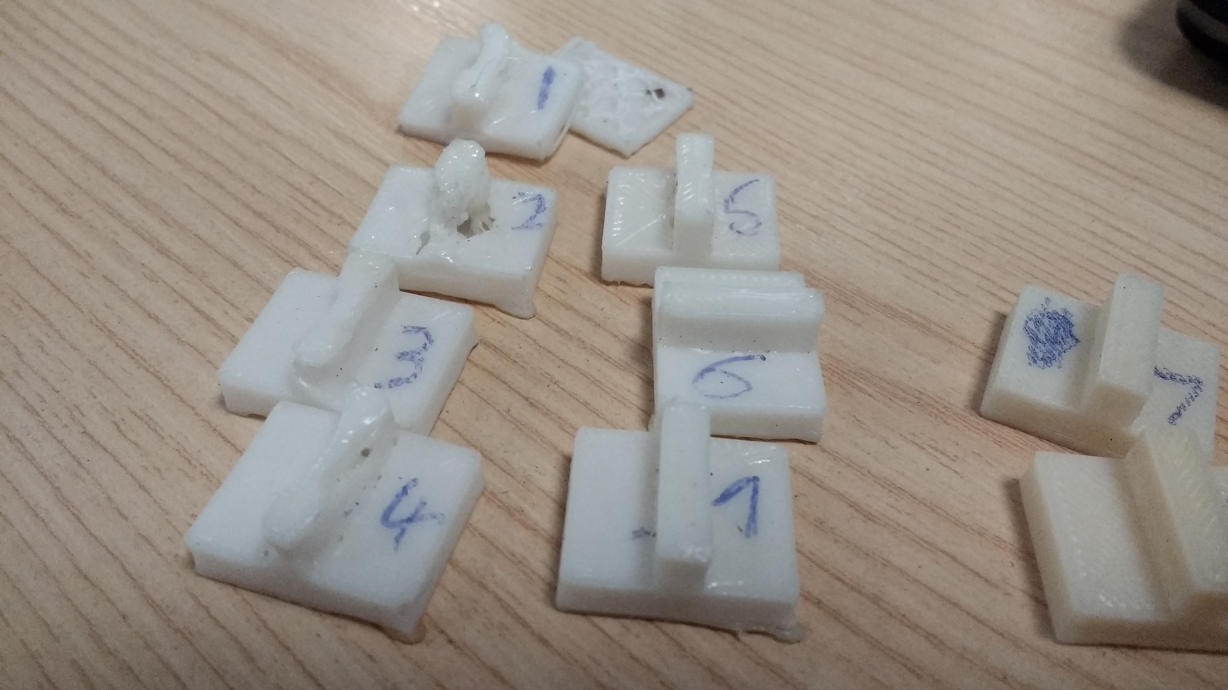
Heres a bunch of prints where you can see on parts 1,2,3 and 4 how the support structure has collapsed.
 The second issue is that there does not seem to be a practical way to set each extrusion head separately. The temperatures can be set independently but that is about it. This means that for dual extrusion, you need to optimise the printer for the most critical material (flex45 in this case) and then play around with the available settings to get your secondary material printing OK. This may result in your prints being a little less crisp than you are used to.
Dual extrusion
Once the printer was setup I thought I would try a dual extrusion of a simplified finger joint. The ABS ran out half way through and the new reel didn't seem to print as well as I would have liked. The alignment of the 2 parts was perfect though, so i'll call this print a success in that it's a proof of concept.
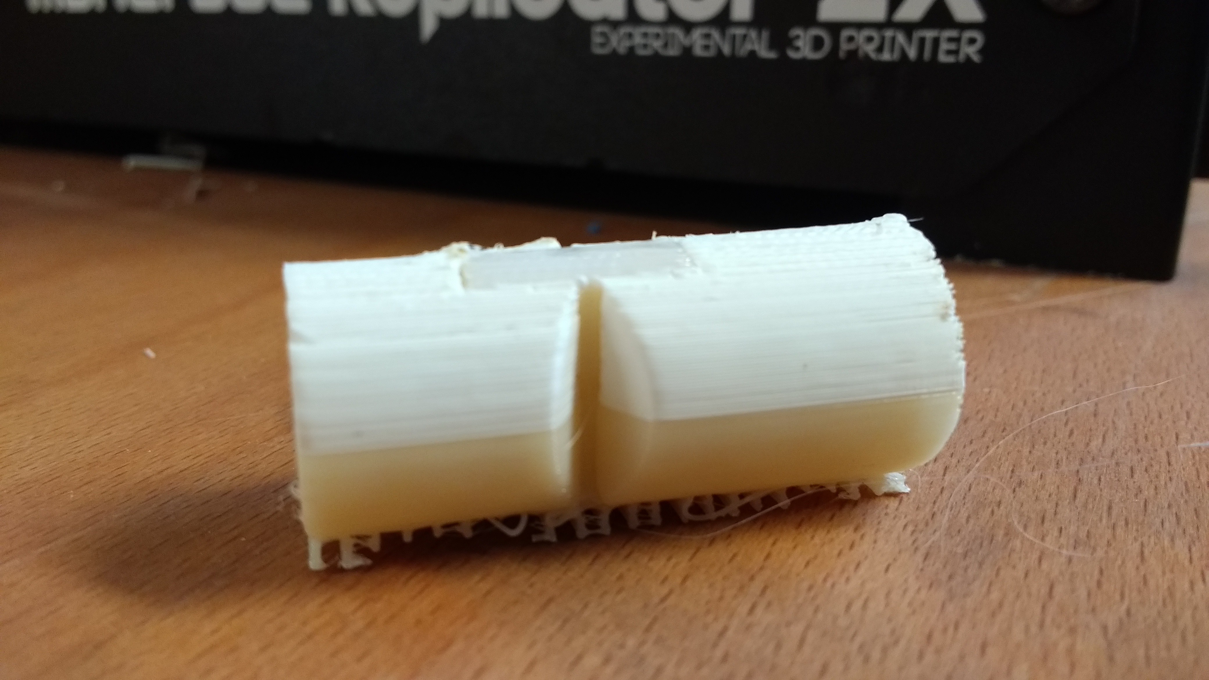 The adhesion between the different materials was not great, once the joint was bent to the point where the two ABS parts contacted each other it did not take long for one side to detach from the flexible joint. Two things will be changed for the next one. Firstly, there will be more clearance between the stiff parts. Secondly, I will shape the joint in such a way that there is a form of mechanical retention. This could be done by making it a bow tie shape with the thin bit flexing in the middle.
Here is the separated part, the joint doesnt seem to want to come out of the other side: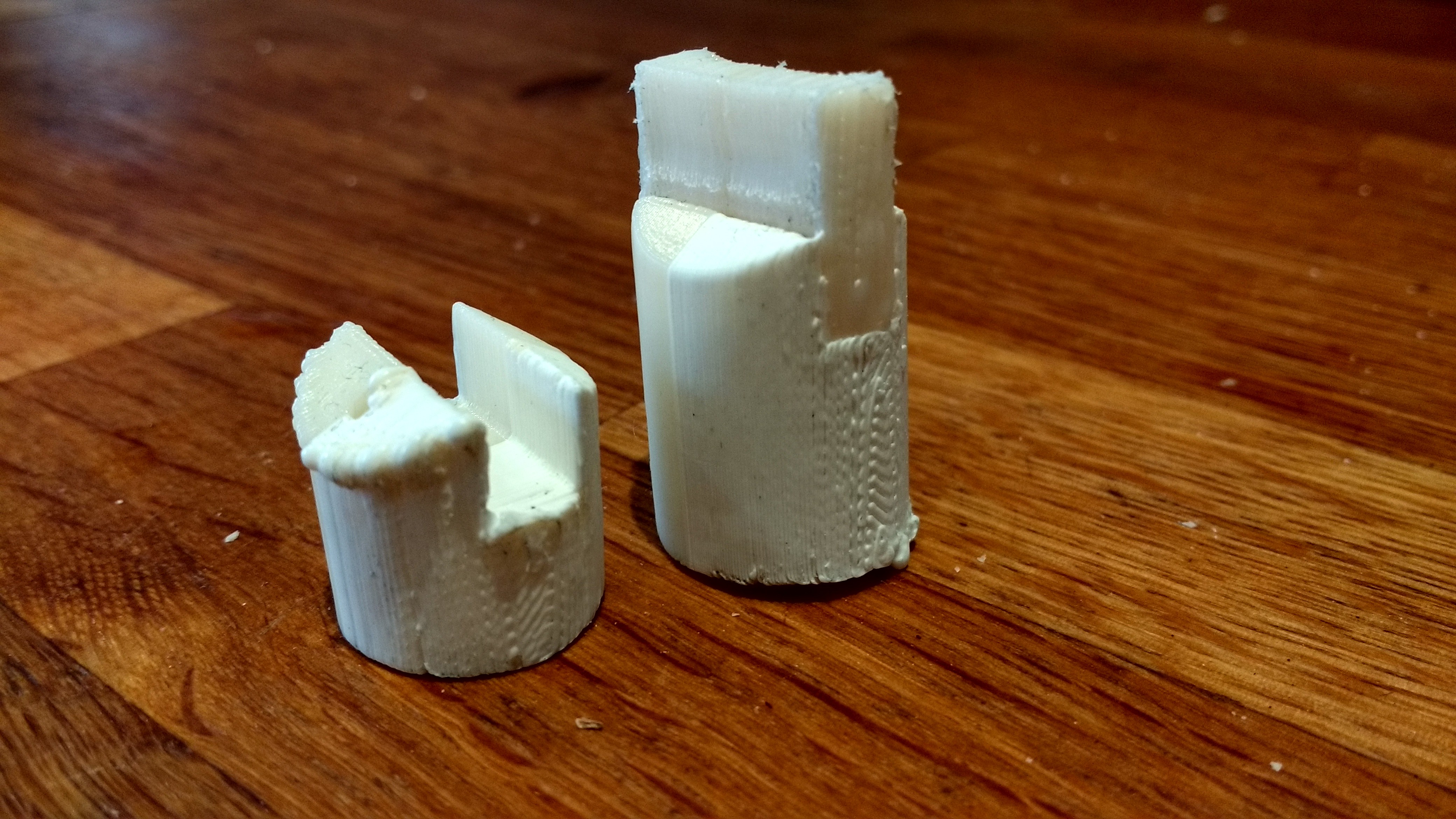 Update September 2017
After a summer using this printer and these materials for a university research project, the printer has stopped working. I have however found a Goprint3D printer that I can use with a build box of just under a cubic metre.
I have successfully printed with TPU95 flexible filament, I can't show the results here due to it being a live uni research project and it may be commercially sensitive. I'm going to call this project a wrap, because I don't have the tools I need any more.