0%
0%
Funktion Generator
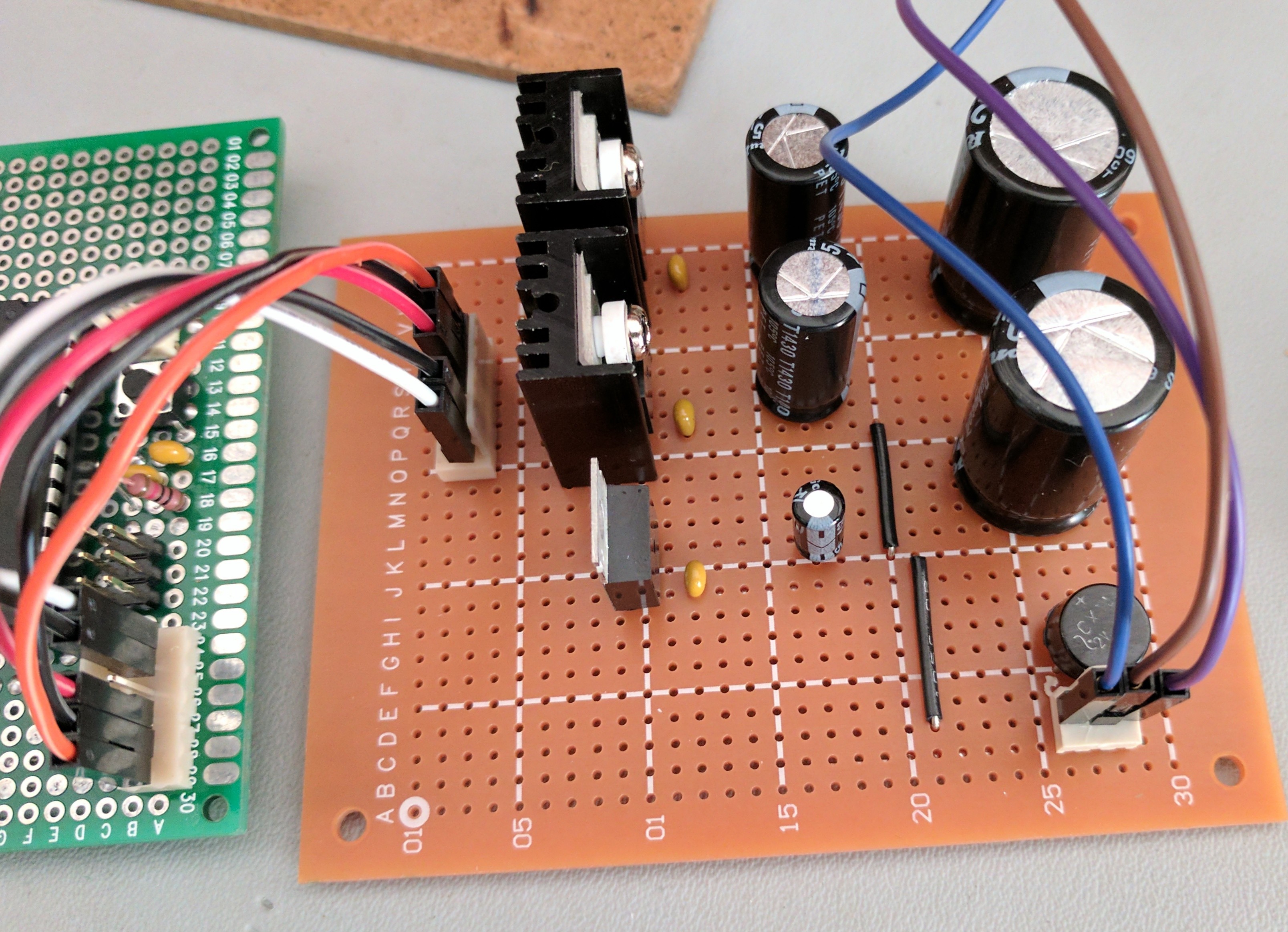
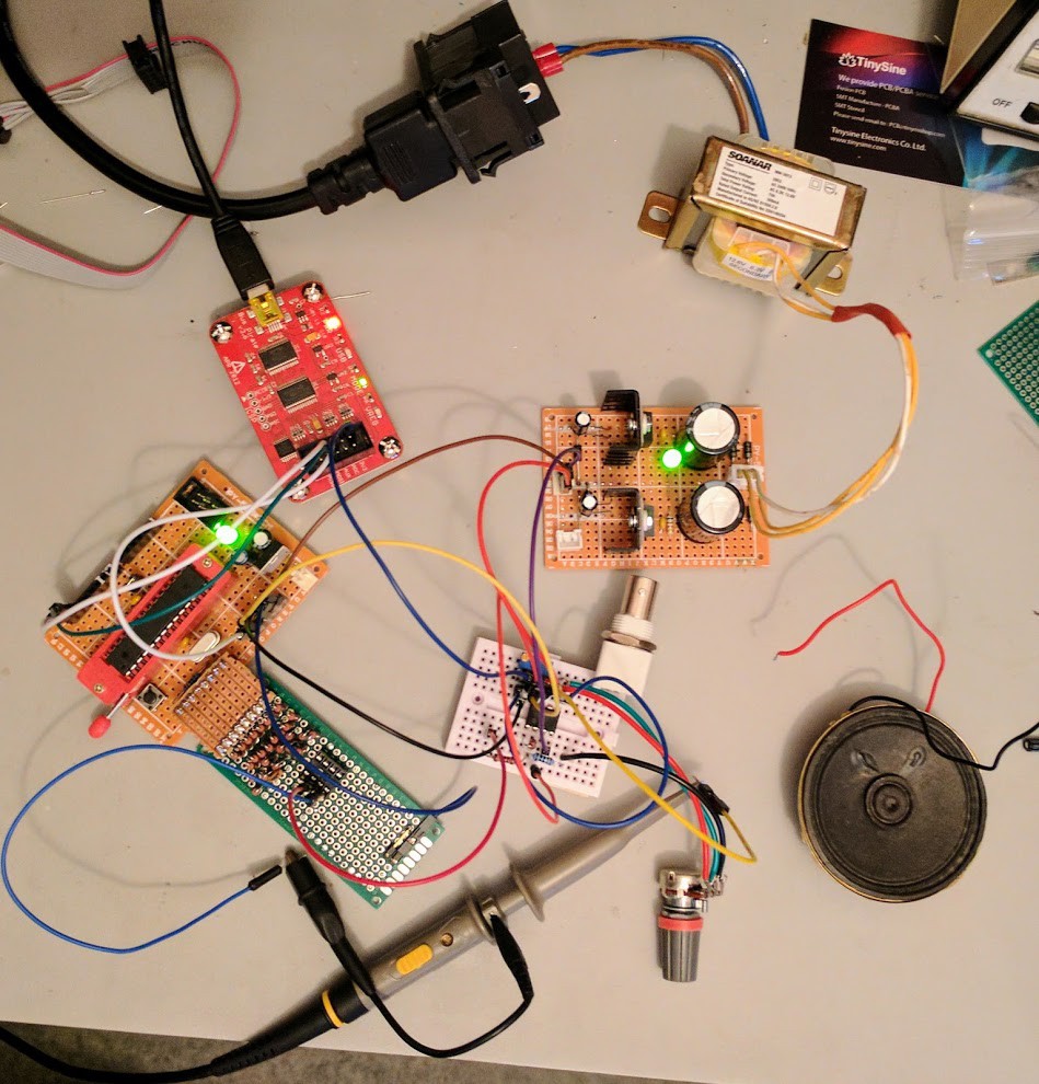
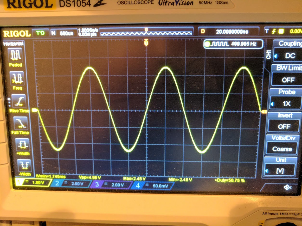
An AVR DDS function generator.
 Tim Savage
Become a Hackaday.io member
Already have an account? Log in.
Just one more thing
To make the experience fit your profile, pick a username and tell us what interests you.
Pick an awesome username
hackaday.io/
Your profile's URL: hackaday.io/username. Max 25 alphanumeric characters.
Pick a few interests
Projects that share your interests
People that share your interests


 Richard Coleman
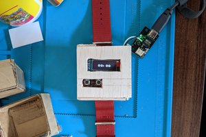
 Maso
Maso
 Denis
Denis
 Bharbour
this project it's dead??? Too bad it seems a great project and very well documented