0%
0%
Software Phase Locked Loop
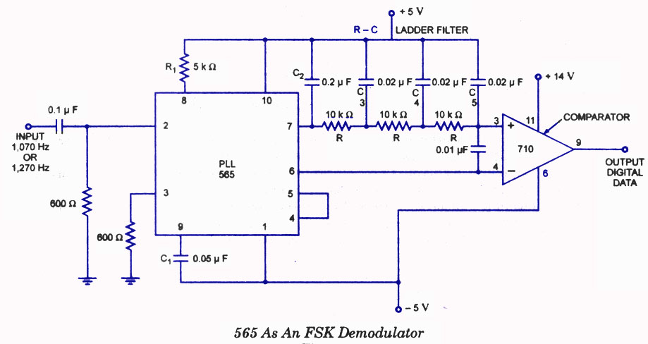
The 567 tone decoder is perhaps most famous Phase Locked Loop (PLL) chip.
This project looks at an Arduino software PLL.
 agp.cooper
Become a Hackaday.io member
Already have an account? Log in.
Just one more thing
To make the experience fit your profile, pick a username and tell us what interests you.
Pick an awesome username
hackaday.io/
Your profile's URL: hackaday.io/username. Max 25 alphanumeric characters.
Pick a few interests
Projects that share your interests
People that share your interests


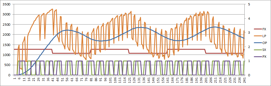
 What when wrong?


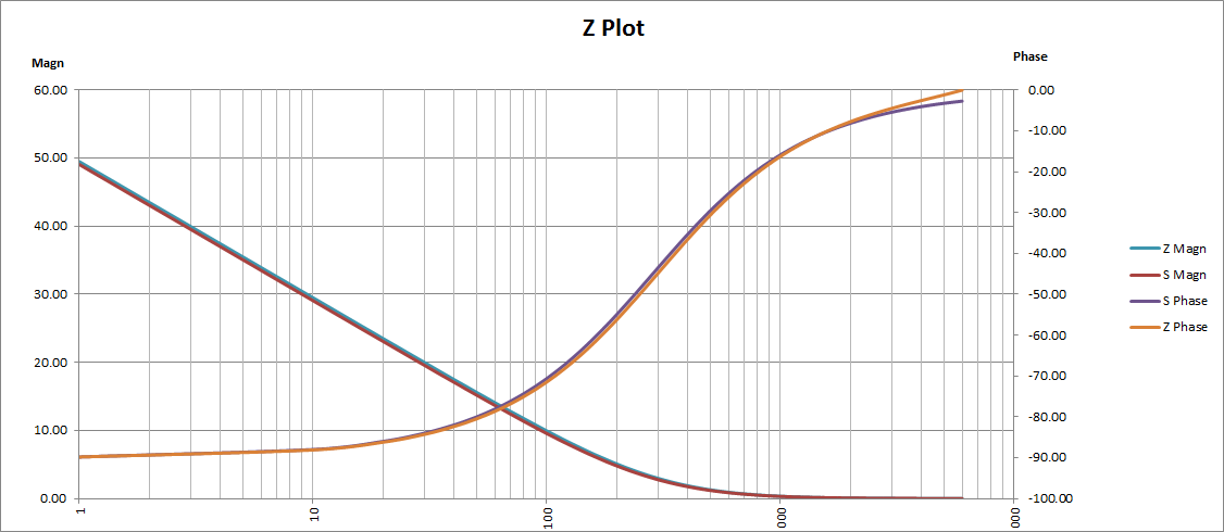
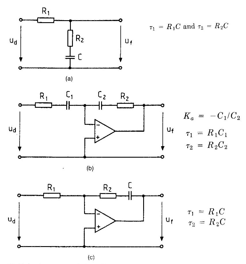
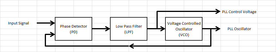
 This can be modelled as:
 (source:


 Ted Yapo
 Mark Omo
 Lilia Lobato
Your endeavor is incredible. This endeavor has given me a lot to learn. I'd want to distribute it to the gyb team so they can read it and apply something fresh to our ongoing efforts.