 Morning.Star
I've been tinkering and refining the basic design of the shells and working out a repeatable procedure that anyone can follow.
Mark was happy to volunteer as a guinea pig to build the second generation parts blind from a template without instructions. Other than following the previous design and building a set of parts, he doesnt have any prior modelling experience. Here is the result.
Mark chose the most complicated part to begin with and piled right in.
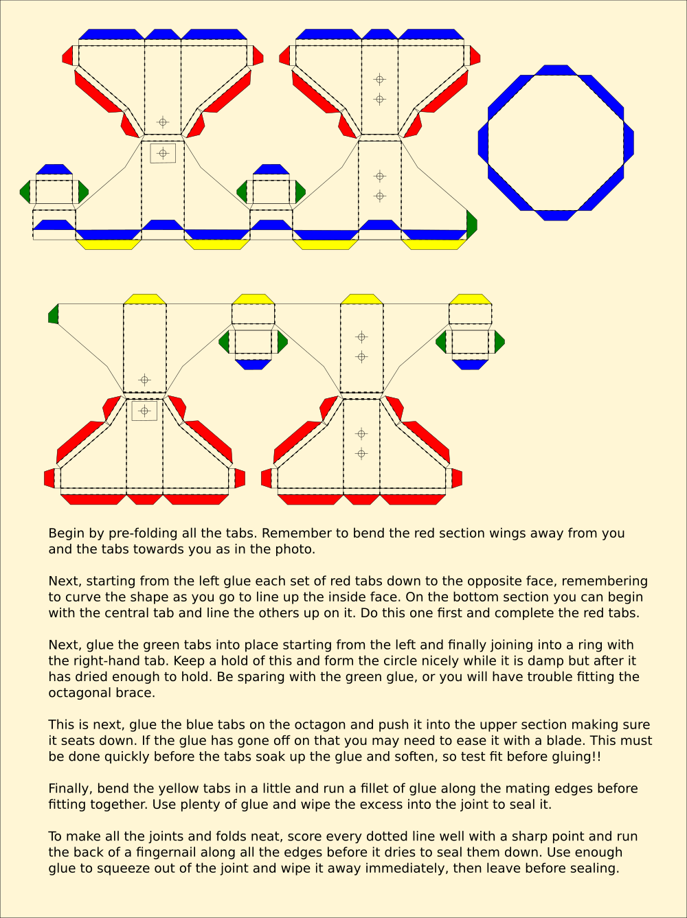
First he printed the latest set of beta templates. They have no lettering or numbering on them and just dotted lines to indicate the folds. These he scored with a sharp point, and then cut out the parts carefully with a craft knife and a rule. You can use a pair of fine craft scissors equally well, this is what I use for the bulk of the build.
These are the instructions he used.
After a while Mark managed to produce this. Not bad for a first time attempt at Origaime, I would say that the system works.
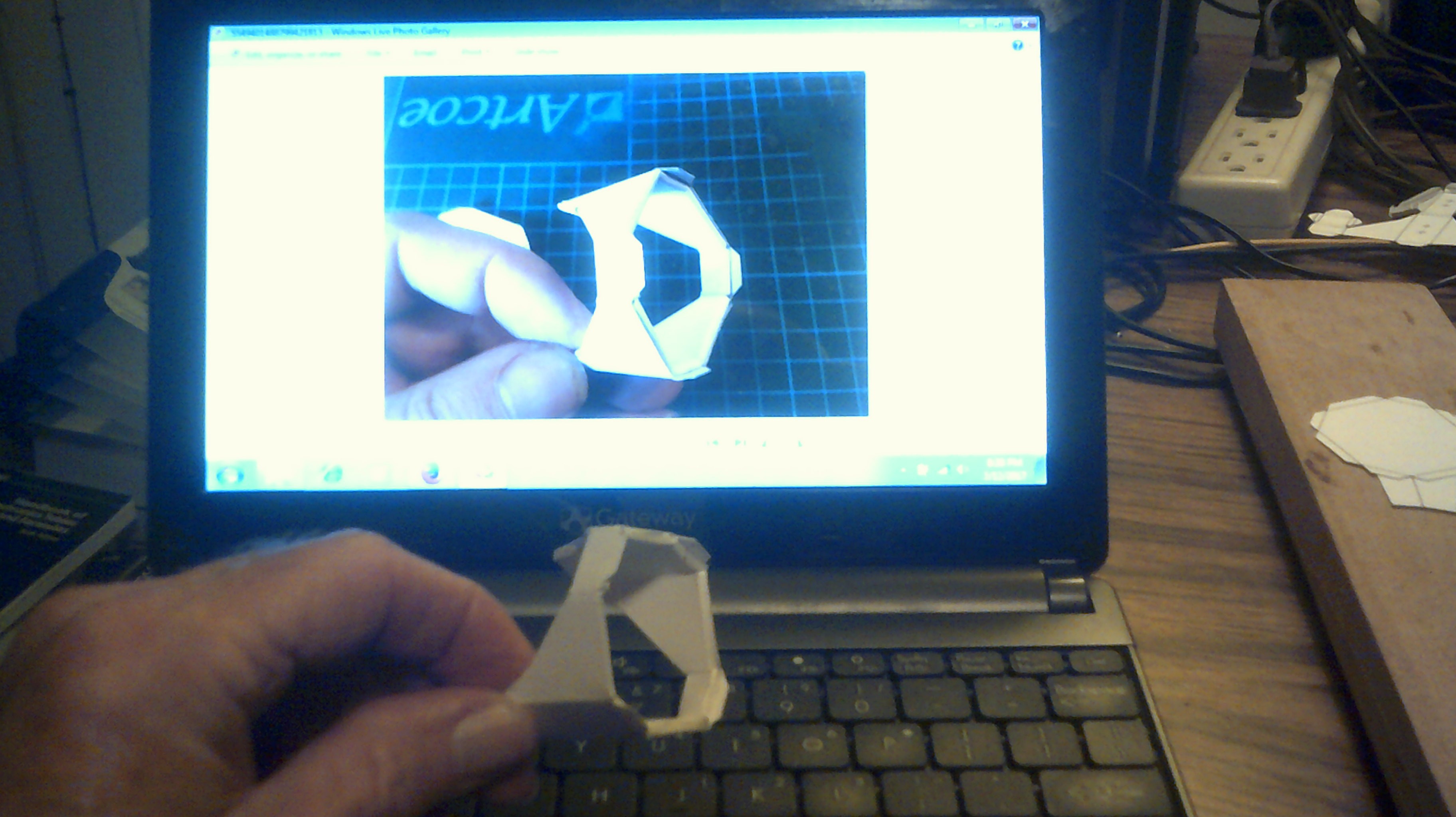
Encouraged by the success, the other section went together smoothly I gather. Mark is using a general-purpose clear contact adhesive to glue his card. This does not wet the card and make it soggy but dries faster. It is harder to keep off your fingers than the traditional PVA that I favour. This takes longer to grab the card and softens it so I can seal edges and fill small gaps. The overall strength with either is more than adequate, so it is a matter of personal choice. Superglue also works but is not recommended, as are other types of glue.
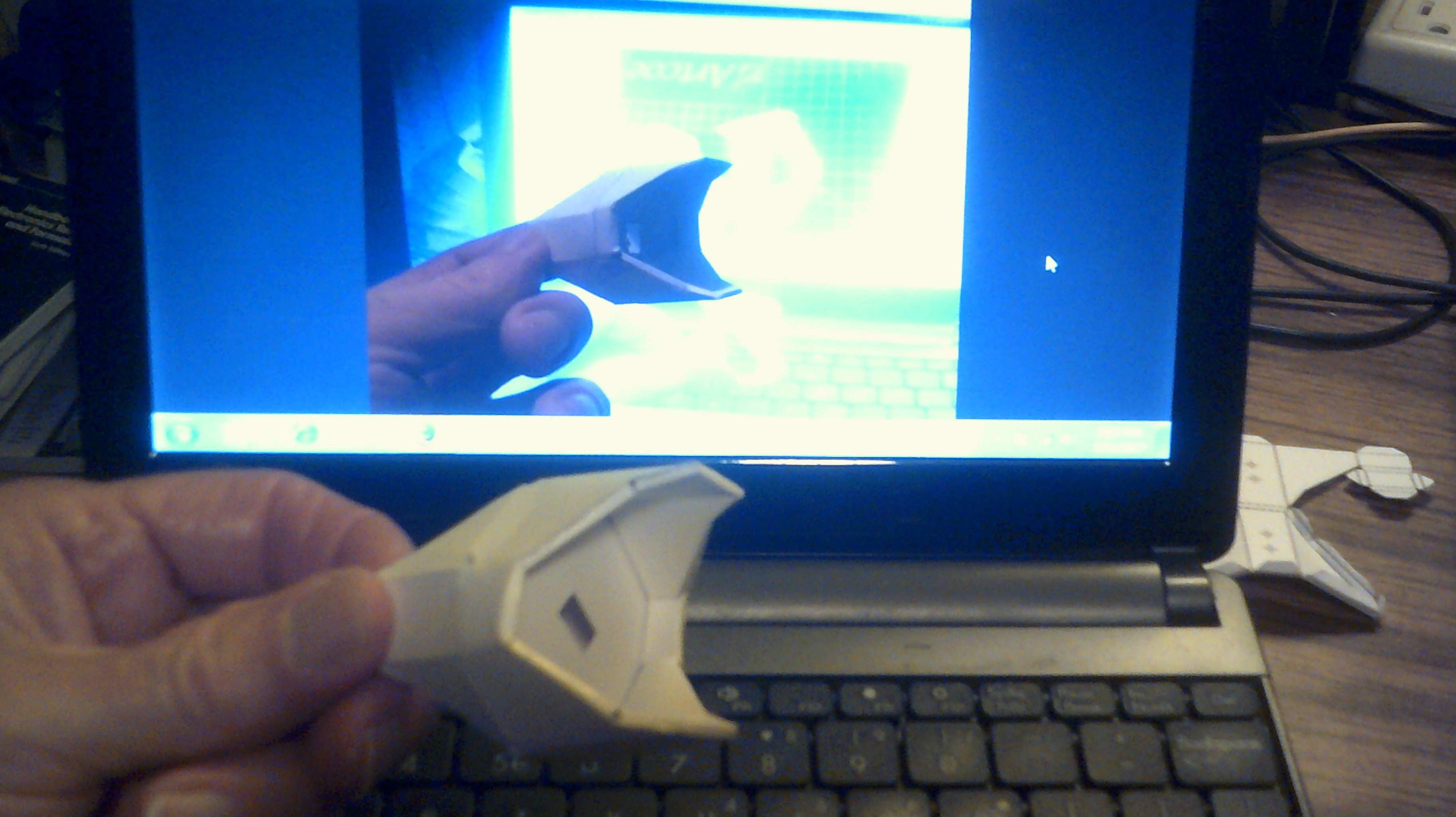
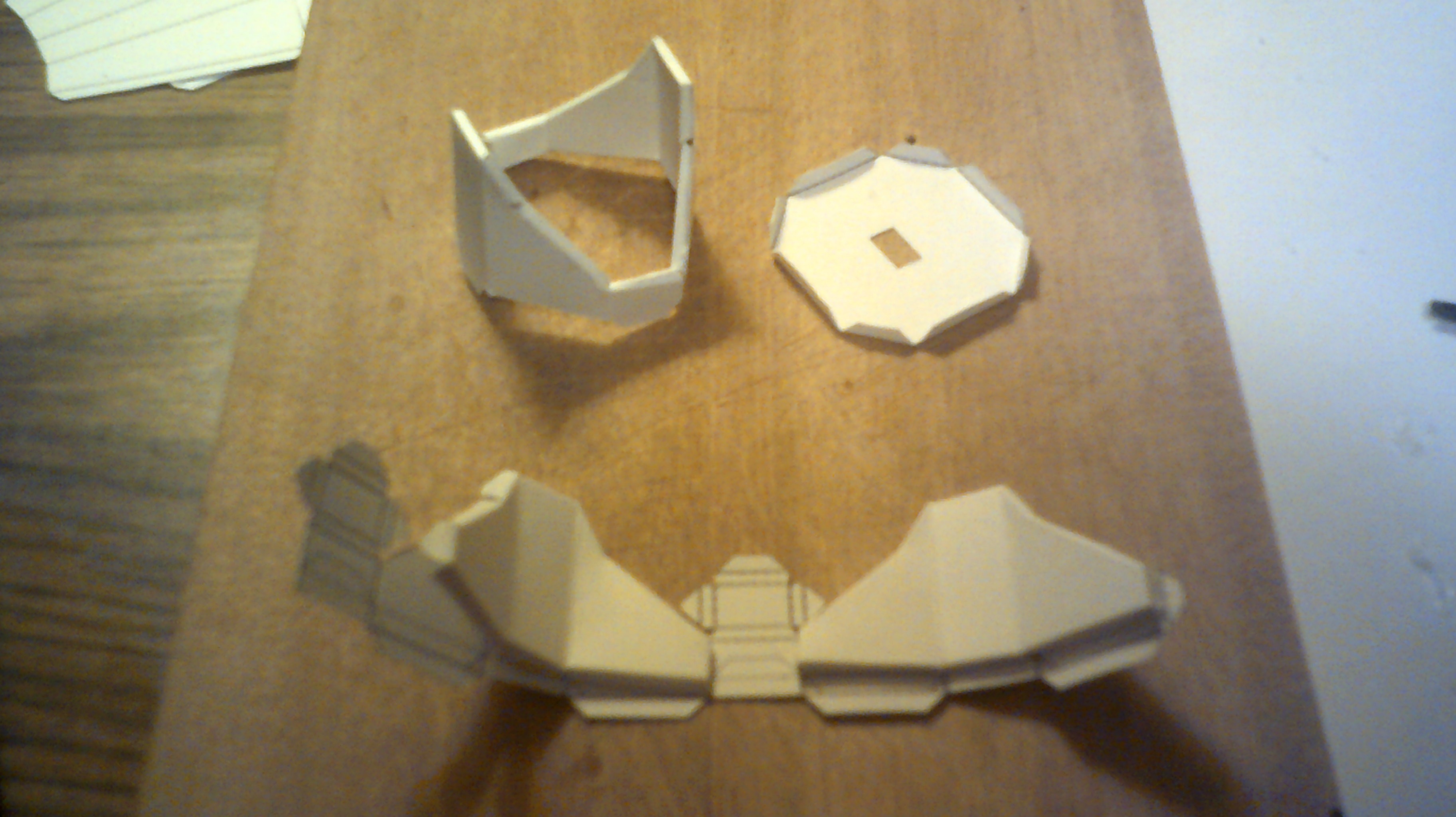
Other parts followed...
 Mark said he likes how these parts just fit together by themselves almost - the foot folds up and lines itself up as you drop it down the cone of the leg for example. This is how I'd envisioned it. The Way of Origaime means that things fit where they are supposed to either by folding or interlocking.

I've also experimented with other card out of interest. To print this, I gummed an A4 paper template to the black card before cutting and scoring. If you can buy black paper, why cant you buy white ink for your printer hmm?
Intersections
This is what is meant by Cardware being an educational system. It is a paradigm that takes minutes to learn, hours to practise, and perfect to a level where you can produce these parts from blank card as Mark has done.
A tidy exoskeleton that can be constructed cheaply and easily is only part of the story. There is also the sensory system to consider. In between redesigning the limbs, I've been trying to make the nervous system easy to construct too. After a fashion we discussed other ways of making an antenna besides sticking foil patches to the card. The layout and wiring for this became too complicated, so we looked at other topologies.
Mark has spent a good deal of time and effort tracing down grounding issues in #The Cardboard Computer - IO is my name. Due to the 'rats nest' of wiring, he needs significant decoupling to prevent misfires and false triggers in his logic chain caused by stray signals. He'd noticed it responds to the presence of his hand like a radio circuit does, and suggested using thin wire glued to card to make deliberate antennae for Cardware. What is bad for the gander is good for the goose as they say however.
This is the resulting antenna module. The generation 1 system used 1 port per patch from the MCU, so I have designed a circuit that multiplexes 8 ports into a bus. This has 5 address bits, one for each leg and one for the body, and 3 id bits so each limb has 7 distinct patches on it, as does the body.
There is no reason why the antenna cant be built to accommodate 255 distinct patches on the surface, or more by extending the bus.
The lower leg section has four of these antennae joined together to pick up motion near, and touches on, each side of the limb. There are others embedded across the shell.
I'm waiting on servos, and Mark is waiting on his system hardware before we can test it thoroughly.
If you want a complete set of templates, please ask.
Discussions
Become a Hackaday.io Member
Create an account to leave a comment. Already have an account? Log In.
Hey, I was just looking into touch sensing myself, and instead of using a general purpose pin multiplexing chip or a shift register, I found the AT42QT1070 I2C chip. This is pretty nice, because it already handles the capacitive touch sensing for you -- so your MCU can do other stuff. It gives you 7 buttons, and connects to the I2C bus, so doesn't really consume any pins. Unfortunately, it only has one hardwired i2c address, so you can only have one such device on your bus. But I think it's still an interesting alternative to consider, and I'm sure there must be more similar chips out there.
Are you sure? yes | no
Hey Radomir.
Capacitive sensors are pretty new, and the modules are basically an MCU with the same type of code plus an I2C driver. Capacitive sensing has been around for ages, see Makey-Makey for a good example, but everybody is using one pin per touch pad. I've figured out a way to stack the sensors and turn them into a bitwise multitouch bus. It also works using ribbon cable as a terminal sensor. ;-)
As it stands we're using a Mega1284P as it has enough pins for 13 servos and an 8-bit sensory bus. This is divided into a linear 5 line bus with another 3 bitwise IDs that gives us 7 touch 'pads' per limb and another 7 on the body. By wiring the sensors with 8 individual wires we can have 255 individual touch pads without any extra hardware or processor overhead. We're trying to avoid proprietary technology as much as possible.
The antenna works by measuring changes in an RC circuit. This is why it is wired zig-zag to eliminate EM response. ;-)
Are you sure? yes | no
Thanks for the explanation. I see you are going for the monolith approach, to squeeze as much as possible from the platform, which is both efficient and a fun challenge.
Personally, after trying that for several years, I now lean more towards separate subsystems with dedicated functions -- for instance, a separate servo controller board. This lets me develop and test the subsystems independently, and also replace them if I want to try a different approach, without having to rebuild the whole thing.
In any case, I can't wait to see it move!
Are you sure? yes | no
Radomir, thats a good plan for an individual system.
I wouldnt say this was monolithic, the 1284 is a subsystem for the Pi network sitting on top of it. One or two inside the shell, hopefully thousands of others in other robots. That's so I dont have to use the Pi for the donkey work of controlling the servos and clocking the sensor bus. We've also got audio and video input hence having a number of processors. It's there to simplify the hardware at the bottom level...
Cardware is the transport for a distributed sensory computing system, not a single robot. ;-)
Are you sure? yes | no