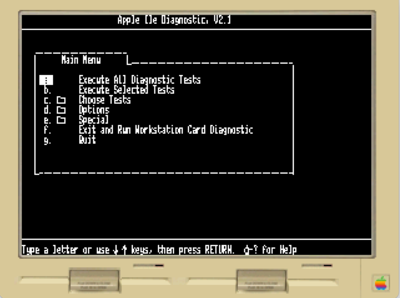
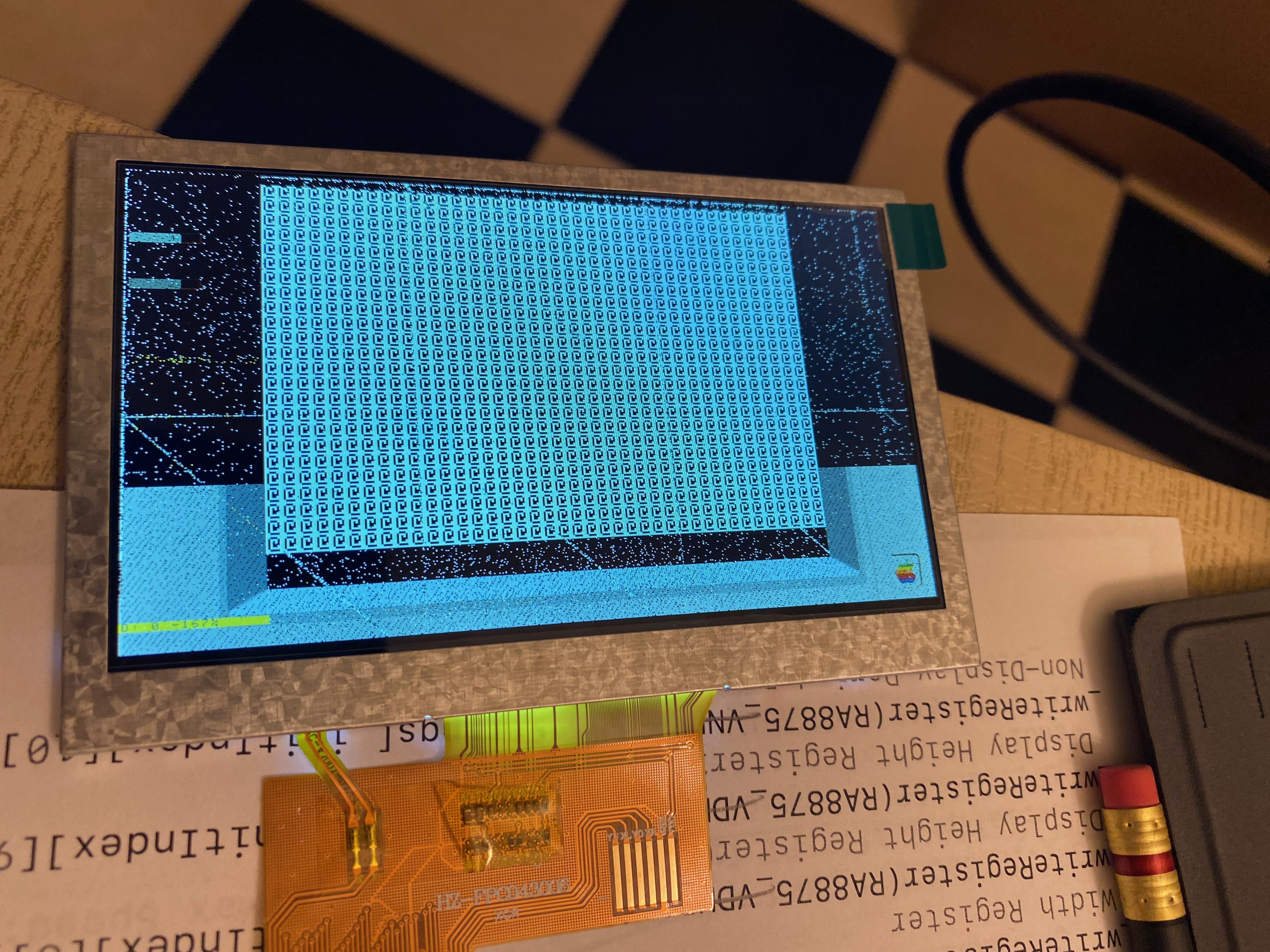
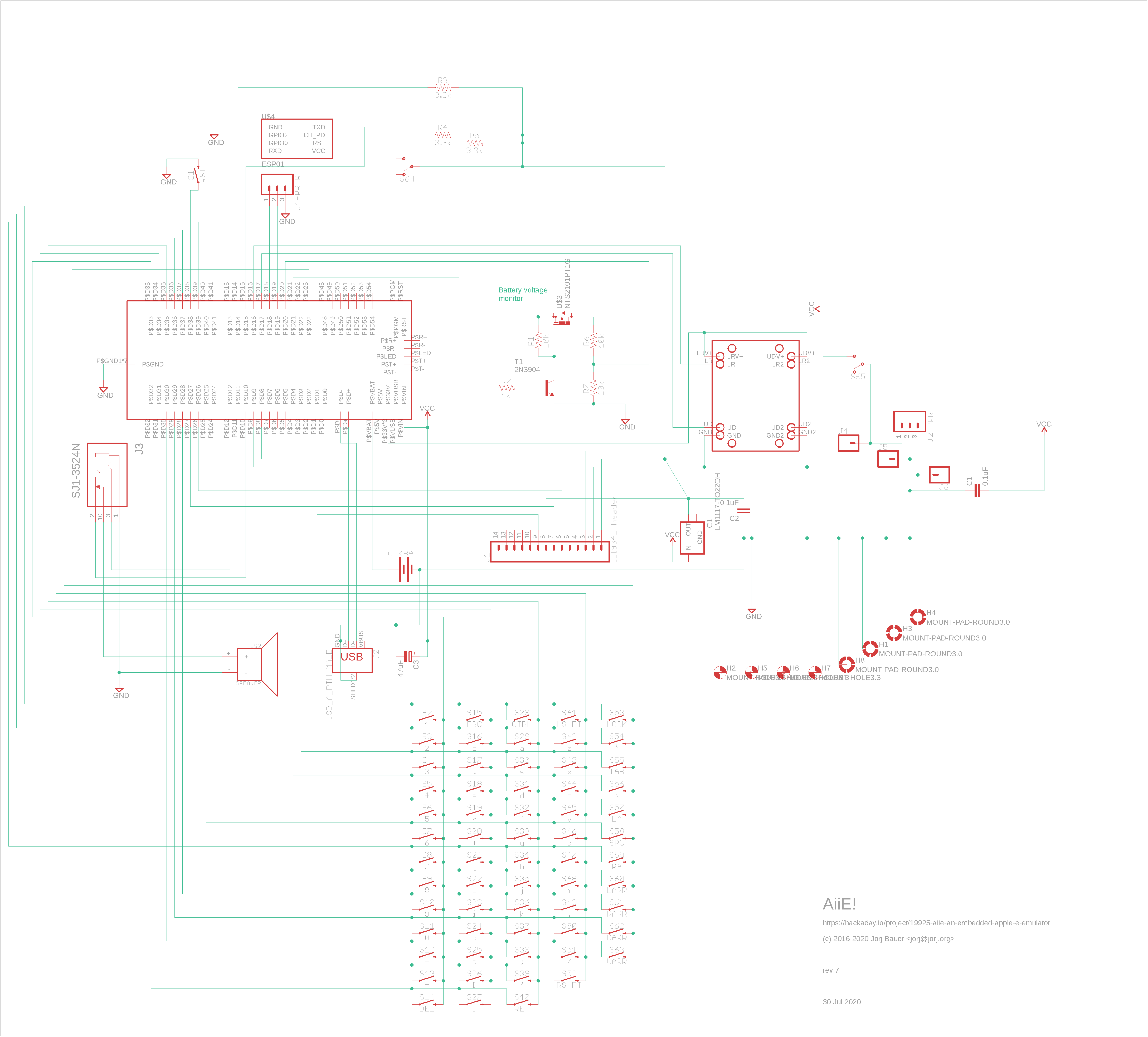
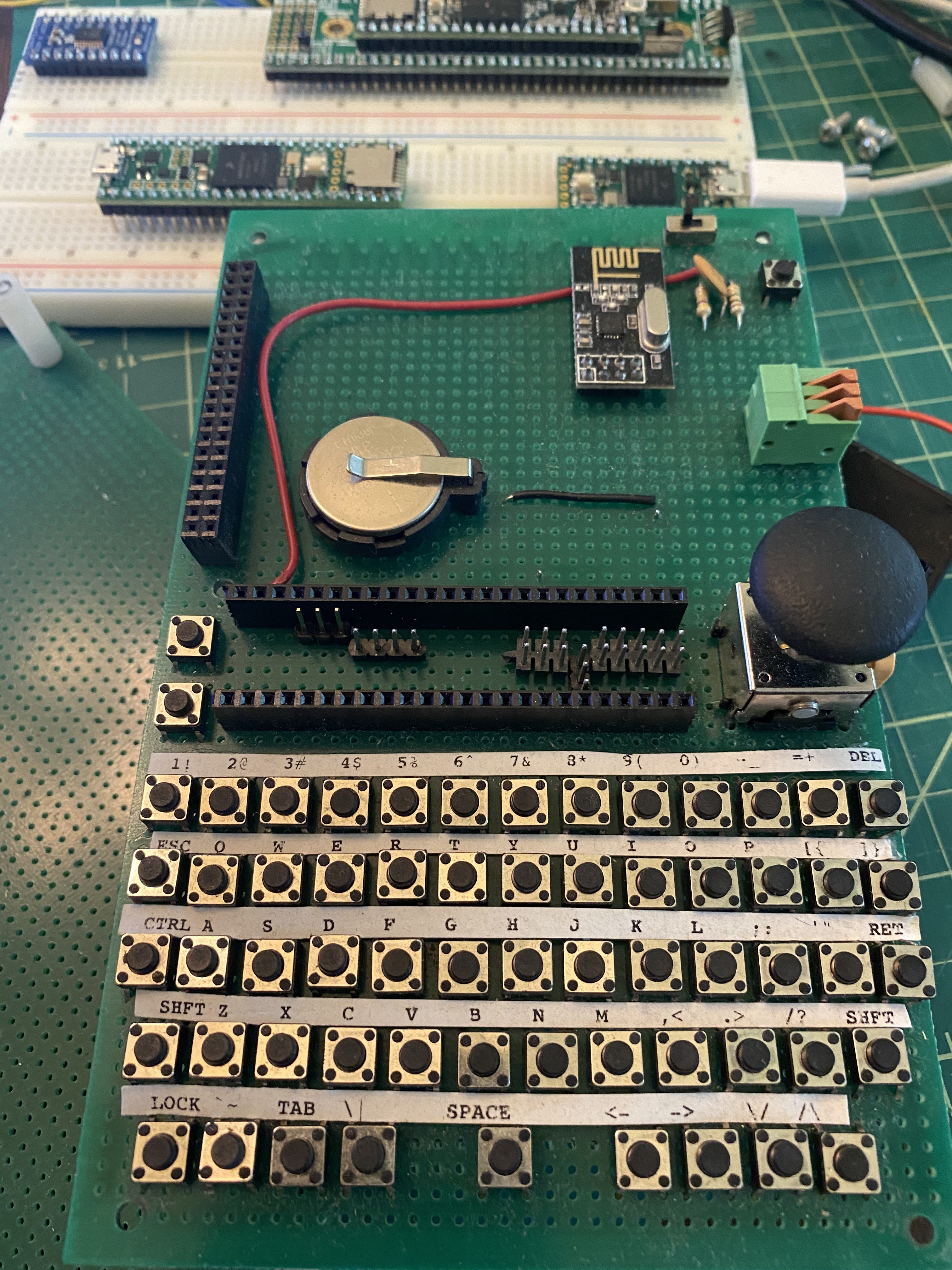
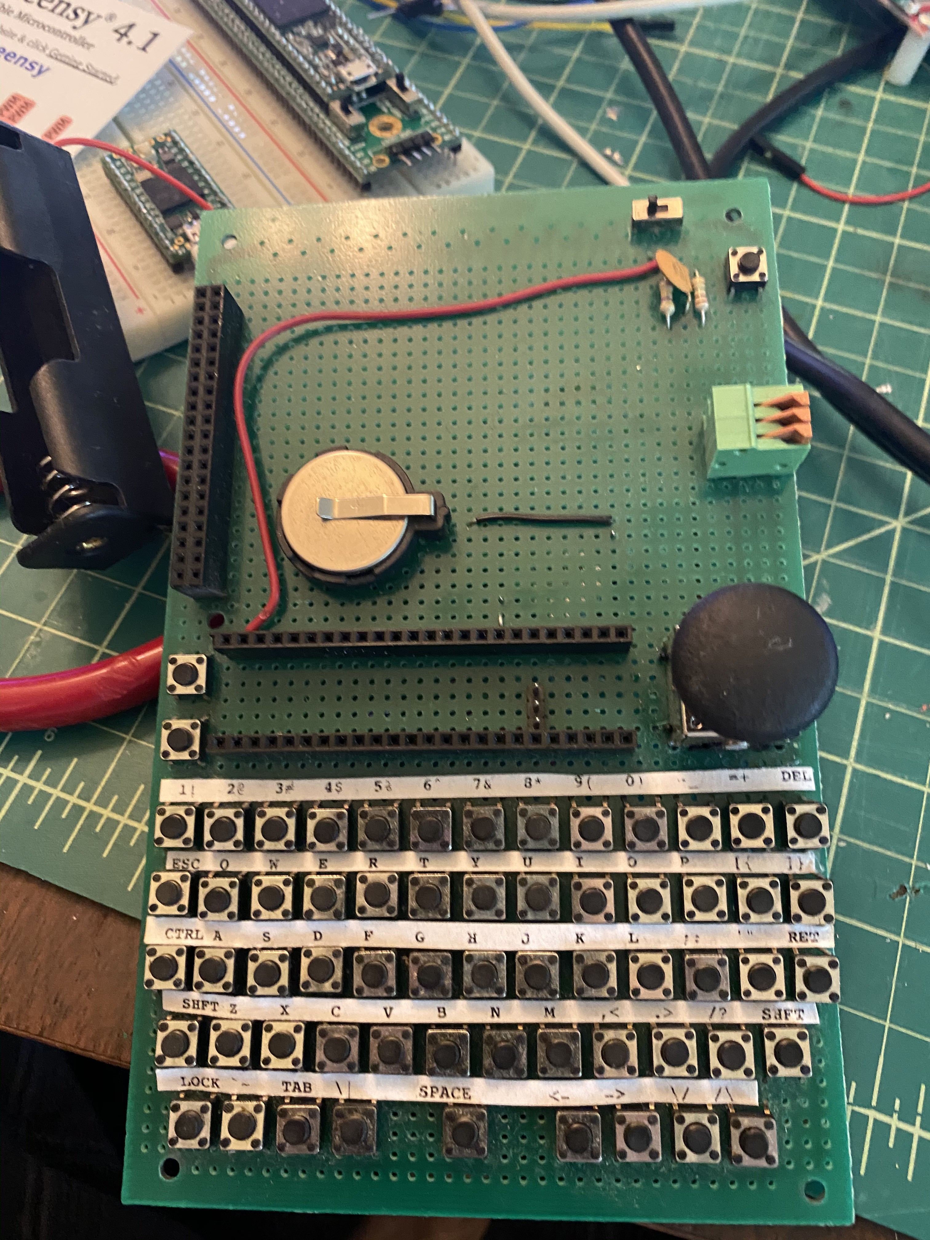
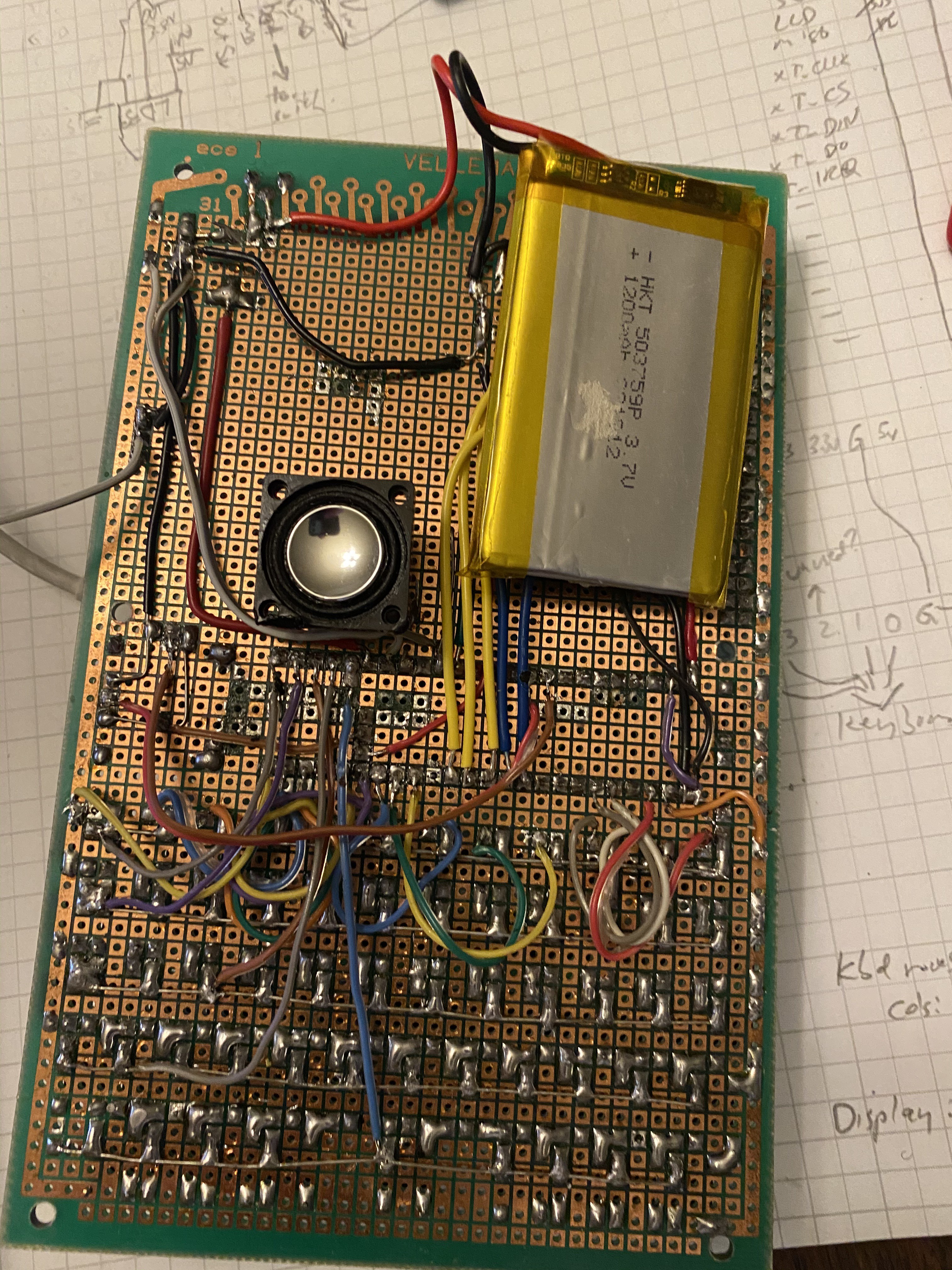
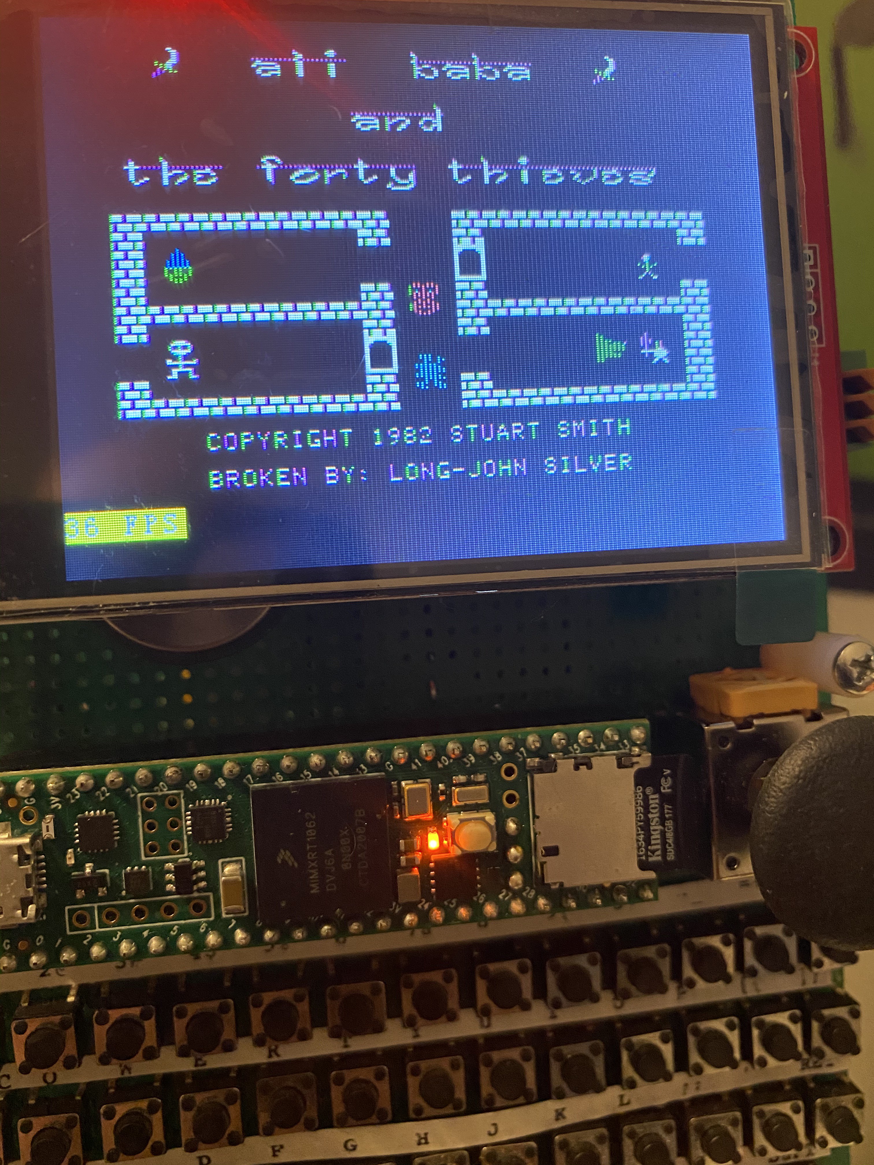
• Entry 29: A Little Bit of This, and a Little Bit of That...

    Jorj Bauer02/10/2022 at 21:45 0 comments

    As I've been writing in the last few updates: I've been working on support for the RA8875 display - so the next generation of the Aiie will have a display that can accommodate the 560 pixels wide that the Apple //e has in "double hi-res" modes (80-column text, double-low-res and double-hi-res graphics). That's all because without it, AIie has been doing some janky hacks to display those graphics modes on a panel that's only 320 pixels wide.

    Most of what I'd think someone uses a handheld //e emulator for doesn't involve 80-column text, so until now I've sort of ignored the problem. It wasn't until I heard from Alexander Jacocks about how he was building an Aiie that the topic came back to the fore. I opened up a discord for us to chat, and we've been talking about what's lacking in the current build... and of course the display was the number one hot item.

    We've spent a couple months talking about the hardware and software with a few other people that have also joined our discord, and (as I've written) we've got the 800x480 panel up and running at about 14 frames per second.

    It's looking like we won't get past that point. We're pushing the display's (single) SPI bus as fast as it will go. It's possible that some hack can get a little more out of it (if we abandon the display outside of the "apple" screen area then it might be possible to only update the 560x192x2 pixels of the "Apple Screen"); and I've got some framework for only updating the parts of a screen that have been modified by the Apple emulator... but when all is said and done, if a full-screen game is updating the whole screen, there's not much you can do about the lack of bandwidth.

    I think that's kinda okay. If I rebuild the PCB so it can accommodate either the ILI9341 320x240 display *or* the HA8875 driver from Adafruit with a 4.3" 800x480 display, then the user can choose -- do I want 30 frames per second with the smaller display and some graphics issues at higher resolution, or do I want all the pixels at half the speed? Putting the choice back to the builder feels like a reasonable trade-off to me.

    Which brought me to the next crossroad. I don't want to abandon the folks that have already built an Aiie. The original Mk 1 is a dead end, unfortunately, because of lack of CPU to do what I wanted. But the Mk 2 has plenty of capacity and I really don't want the addition of a new display to strand folks; I still haven't taken advantage of everything those have to offer! How can I continue to support the Mk2 platform without having to fork the software?

    Well, that's not too hard actually. Since there is plenty of space in the Teensy, it doesn't mind having two copies of the graphics and two display drivers built in. Take one of the unused pins from the Mk2, turn it in to a jumper or switch, and /Voila/ you've got selectable displays. Buy both if you want, and swap them as necessary. (This may not be ideal when we get to having an actual case, but for now at least it's plausible.)

    From there I dropped back to the *nix variants of Aiie. I do most of my development and debugging on a Mac, using SDL libraries to abstract the windowing. It had been doubling the resolution of the ILI panel... but I've undone that. Now that the Teensy code supports two different displays with different resolutions, the SDL wrapper does the same... and when you're running it with the ILI ratio, it's natively 320x240 and not 640x480. Which means that, among other things, it became very ugly very quickly... and now this problem that has existed on Aiie since the start suddenly became a priority for me.

    My first take at this was to logically "or" every two pixels together. If either of them is on, then the result is "on".

    The text is sort of legible... but that white rectangle with the three dots in it is the letter 'a', inverted. As long as we're talking about black-on-white text it's... meh, probably okay.

    Next up we have straight linear average: average...

    Read more »

  • Entry 28: Collaboration via Discord

    Jorj Bauer01/23/2022 at 00:32 0 comments

    I've been collaborating with a few individuals on Discord the last month or so. I've got bits of development and a lot of discussion going on over there, and if you're interested, drop on by. I don't know if this will work out long term but it's at least an interesting experiment...

    Discord server invite: https://discord.gg/NRhMS6fRgZ

  • Entry 27: on DMA with the Teensy 4.1

    Jorj Bauer01/22/2022 at 20:10 0 comments

    As part of the RA8875 display work, I had to build a new framebuffer and use the Teensy's eDMA system to automatically shuffle bytes out the SPI interface. In doing that I learned quite a lot about how the eDMA interface works, and what the magic code in the ILI9341 and ST7735 libraries does. I left a lot of those comments in my RA8875_t4.cpp module but I thought an out-of-band write-up would be really useful (for me for later, if not for others trying to do the same thing).

    To begin with: download the IMXRT 1060 Manual from PJRC. The inner workings of all of this is documented in there, but it's not all in one place and can take a while to find (in the 1100-whatever pages of documentation). Eventually you'll be looking for data from it.

    For me, the general path of getting this all working was:

    1. Get the display initialization working by reading other sources and duplicating what they did.
    2. Implement synchronous transfers on-demand to draw pixels, clear the screen, and whatnot.
    3. Build a framebuffer and update that instead of calling the synchronous methods.
    4. Build a synchronous update from the framebuffer.
    5. Implement a one-time DMA-to-SPI transfer that reads from the framebuffer and then stops.
    6. Turn on continuous asynchronous updates from the framebuffer.
    7. Remove all of the (now-unused) synchronous code.

    The display initialization and LCD workings I'm not going to talk about too much - mostly it was a combination of looking at the RA8875 module distributed with Teensyduino 1.56 and looking up constants in the official display manual. The same is true of synchronous transfers -- a lot of copy/paste/delete/rewrite as I began to understand how the display itself works.

    The framebuffer code itself is pretty straightforward. I needed an array for 8bpp 800x480, and declaring it is relatively straightforward:

    DMAMEM uint8_t dmaBuffer[RA8875_HEIGHT][RA8875_WIDTH] __attribute__((aligned(32)));
    

    A refresher from my last log entry: DMAMEM tells the Teensy to put it in RAM2, which is perfect for DMA to use; the height and width constants are 800 and 480 respectively. That just leaves the attribute, which is important for DMA -- it can apparently be picky about the alignment of the buffer it's copying out of. (I didn't have any problems with this, but then again I was forewarned and added the attribute. YMMV.)

    From there it's just a matter of doing some pixel math -- whenever something needs to be drawn to the screen, calculate the proper index in to the array and store the pixel instead of pushing a command to the LCD to do the same work. Taking that buffer of data and feeding it to a synchronous update proves that I know how to interact with the display itself - initializing its display window, starting a new SPI transaction, telling it I'm sending memory data, and ending the transaction when done. Nothing difficult so far, just very very slow to perform its work. This is how I'd transfer all of the data to the display in a synchronous function:

      _writeRegister(RA8875_CURV0, 0);
      _writeRegister(RA8875_CURV0+1, 0);
      _writeRegister(RA8875_CURH0, 0);
      _writeRegister(RA8875_CURH0+1, 0);
    
      // Start it sending data                                                                                                                    
      writeCommand(RA8875_MRWC);
      _startSend();
      _pspi->transfer(RA8875_DATAWRITE);
    
      for (int idx=0; idx<800*480; idx++) {
        _pspi->transfer(dmaBuffer[idx]);
      }
      _endSend();
    

    Those first four writes tell the display we're starting in the upper-left corner (Vertical and Horizontal cursor position at 0). Then send a memory write command; begin an SPI transaction with _startSend(); tell the display we're going to stream the pixel data; actually stream te pixel data; then end the transaction and we're done.

    All we have to do is repeat that from a DMA handler!

    Arr, but here there be dragons. Or maybe that's the wrong metaphor. Here there be performers of the dark arts? Certainly poorly documented capabilities that are hard to figure out from scratch. Which is why I leaned a lot on the ILI and ST code.

    A lot of the...

    Read more »

  • Entry 26: Harder, Better, Faster, Stronger

    Jorj Bauer01/22/2022 at 18:23 0 comments

    When I was a freshman at university studying electrical engineering, one of my professors laid this out pretty plainly for us: engineering tolerance is important. If you're designing a system that needs 1 amp of current, your power supply better support at least 2 amps. You want room for failure - particularly when you're first designing something and have no idea how all the pieces will interact. 

    That often means that, if you know what you're doing, you can push past the stated limits of systems as long as you're willing to accept some risks. In the last log entry, you saw me push a 20MHz SPI bus over 26 MHz before it broke. Will every copy of that display get 26 MHz? I don't know, but it's possible. Will something be damaged by pushing it that far? Possibly, but it's not likely (in this case).

    In the quest to get beyond 7 frames per second, this is the realm I'm visiting. What kinds of limits can I bend or break, without causing any significant damage? is there a way to get an 800x480 SPI display over 12 frames per second? Or maybe as far as 30 frames per second?

    The first step is to consult ye olde manuals. What are the variables here and how do they interplay?

    We've got the SPI bus speed. On the Teensy side of things, I see reports of people getting that up to 80 MHz. I've certainly driven it up to 50 MHz. We're not near those potential maximums yet - and the current failure is on the RA8875 side anyway. So what are the limits there?

    According to the RA8875 specification, page 62, the SPI clock is governed by the System Clock - where the SPI clock frequency maximum is the system clock divided by 3 (for writes) or divided by 6 (for reads). The system clock, in turn, is governed by the PLL configuration that's set via PLL control registers 1 and 2 (p. 39). The PLL's input frequency is the external crystal (on the Adafruit board that's 20MHz), and twiddling PLLDIVM, PLLDIVN, and PLLDIVK configures the multipliers and dividers for the PLL to generate its final frequency.

    The system clock frequency is

    SYS_CLK = FIN * ( PLLDIVN [4:0] +1 ) / (( PLLDIVM+1 ) * ( 2^PLLDIVK [2:0] )) 

    and looking at the DC Characteristic Table on page 174, we see that it's "typically" 20-30 MHz with a max of 60 MHz.

    Now, the RA8875 driver (as distributed with the Teensy) sets all of this as PLLC1 = 0x0B and PLLC2 = 0x02, which means sys_clk is 60MHz. Right at the maximum limit specified in the datasheet.

    Will it go faster? If we make it go faster, what else will be affected?

    Looking for all of the references to the system clock, I see that the two PWMs use it. PWM1 is being used to drive the backlight, so that might be important at some point, but probably isn't critical. More importantly: the pixel clock is derived from the system clock.

    The pixel clock is how the data is being driven out to the display. While I see various generalities about the pixel clock required for different sized displays that suggests 30-33MHz for a 800x480 display, I don't have the numbers for the actual display I'm using. And looking at the RA8875 manual and doing the math, it looks like the pixel clock is actually 15MHz here, so those "normal" values are either unimportant or wrong. Either way there's not much to do be done about it until we understand more of what's going on.

    So, let's jump in the deep end! What happens if we maximize PLLDIVN (set it to 31), minimize PLLDIVM (set it to 0) and minimize PLLDIVK (set it to 0 also)? Short answer: nothing. A black screen. So we can't just set it all the way to the maximum. But a little bit of binary searching shows that we can actually set it to other values in the middle and it works with our 26MHz SPI bus just fine, and a sys_clk that's over 60MHz. How far? As far as 150MHz. Along the way I found that the display would break down in very interesting ways... like this, when pushing the SPI bus faster than the clock wanted:

    Or this, when the pixel clock started drifting too far out from what...

    Read more »

  • Entry 25: ONCE MORE INTO THE ABYSS (of displays)

    Jorj Bauer01/22/2022 at 15:04 0 comments

    _Alternate title: "BRING ON THE HACKS"... strap in, it's gonna be a ride.

    When we started brainstorming about Aiie! v10, one of the first questions asked was, "why can't we just use an 800x600 display and show the whole display instead of hacking around it on a 320x240 display?"

    What a lovely, simple, innocuous question. And oh boy what a road it's been.

    Let's start with the physical... what 800x600-like displays exist for embedded systems? There aren't many, and they tend to be fairly pricey. There are NTSC, VGA, and HDMI panels (obviously requiring those kinds of output from your project, which I don't have; I've toyed with NTSC and VGA so either of those would be feasible). If I'm looking for SPI, though - there is basically just the RA8875 chip which supports 800x600 and 800x480, which are both good resolutions for Aiie v10 as discussed in my last log entry.

    I'd like this to be as cheap as possible, though. Which means understanding the parts really well and ultimately deciding if I'm using someone else's carrier board or making my own. The 800x480 40-pin displays are cheaper than the 800x600 displays. And buydisplay.com has them for under $18.

    So some digging later,  I'd bought a 4.3" 800x480 display from buydisplay.com. Yes, it's cheap... but doesn't include the RA8875 driver. Pair it with the $40 Adafruit RA8875 driver board and we should be good to go. Can I make this display work in any reasonable way?

    Well, maybe. Let's look at the software side. There is an RA8875 driver for the Teensy, that's good! But it doesn't support DMA transfers to the SPI bus. That's bad.

    What exactly does that mean? It means excruciatingly slow screen draws. Like, 1 frame every 6 seconds if we're drawing one pixel at a time. This is the actual RA8875 drawing that way...

    That may be terrible, but it gets worse.

    The first version of Aiie used a similar direct-draw model and was always fighting for enough (Teensy) CPU time to emulate the (Apple) CPU in real-time, because it was spending so much time sending data to the display. Not to mention the real-time requirements of Apple 1-bit sound. It was a bad enough set of conflicts that I added a configuration option at some point to either prioritize the audio or the display; you could have good audio or good video but not both. And if you picked video, then the CPU was running in bursts significantly faster than the normal CPU followed by a total pause while the display updated.

    All of that was solved when I converted to a DMA-driven SPI display. The background DMA transfers don't interfere with the CPU or sound infrastructure at all. So I definitely, absolutely, completely want to use eDMA-to-SPI transfers to avoid this bucket of grossness.

    So let's start somewhere real... let's change teensy-display.cpp so it will be able to drive this thing, and see how it goes. Here's one line that's a great starting place in teensy-display.cpp:

    DMAMEM uint16_t dmaBuffer[TEENSYDISPLAY_HEIGHT][TEENSYDISPLAY_WIDTH];
    

    That's the memory buffer where the display data is stored. TEENSYDISPLAY_HEIGHT and WIDTH are 320 and 240, respectively - matching the 16-bit display v9 uses. The DMA driver for the ILI9341 automagically picks up changes there and squirts them over SPI to the display at 40-ish frames per second.

    What happens when we change TEENSYDISPLAY_HEIGHT and TEENSYDISPLAY_WIDTH to be 800x480 instead of 320x240? We get our first disappointment, that's what!

    arm-none-eabi/bin/ld: region `RAM' overflowed by 450688 bytes

    Simply put, there just isn't enough memory on the Teensy to be able to hold the display data. Let's dive in to that a bit.

    The Apple //e has 128k of RAM. The Teensy 4.1 has 1MB of RAM. I would seem, on the face of it, that there should be enough RAM for a 480x480x16-bit display buffer - that's 750k. Yes, there's more overhead in the rest of Aiie... but a rough calculation says that for us...

    Read more »

  • Entry 24: Look at these 53760 pixels that the world doesn't want you to see!

    Jorj Bauer01/22/2022 at 06:50 0 comments

    In 2021, a friend of mine gave me an Apple //e that he'd had sitting in a garage for years. He'd rescued it from a place where another one of my friends had been working, probably around 1996. I've spent a few months cleaning and fixing it up; part of that effort lead me to build the Apple ProFile 10MB Hard Drive reader. It's also gotten me playing Nor Archaist - which my wife bought me for Christmas 2020 - on the actual //e.

    But that's not what I'm here to write about. I'm here to write about how all of this pushed me back to working on Aiie!

    Just as I was thinking about how the //e was going to come back together, someone reached out to me on Twitter with questions about their own Aiie v9 build. Some of the components are no longer avaialble. I never listed why I picked the voltage regulator circuit I'd used (because it's a 1A boost). The PCB pads for the battery aren't labeled (J6 is +B and J5 is GND, but I'd left it flexible for the boost circuit). The version of HDDRVR.BIN (from AppleWin) has changed. The parallel card ROM is one of a pair, so if you have the actual card, it's not clear which one to dump (it's the Apple Parallel ROM, not the Centronix ROM).

    This all got us talking about what else I'd forgotten to finish (sigh, woz disk support; Mockingboard emulation; WiFi). And then we started talking about what else we could do with a new revision of the hardware. Design a case, maybe. Update the parts list. Integrate a charger.

    And update the display.

    Now, most of that was on my roadmap... but I'd convinced myself to forget completely about the display. It's a hack that I'd optimized and considered "done."

    The display on the Aiie! v9 is a 320x240 SPI display (the ILI9341). It's the second display I've used for this project. The original was a parallel interface that required a lot of CPU time to drive; I think I managed to get it up around 12 frames per second. The SPI interface for the ILI9341 not only uses fewer pins, but it can also be run directly from the Teensy's eDMA (extended? expanded? direct memory access) hardware, directly sending the data out the SPI bus without the program manually doing the work. eDMA does a block transfer; when it ends, it automatically starts another one. The frame rate went through the roof. I think I saw it up around 40fps... where anything over 30 is overkill. (Hmmm... the black magic of the ARM IMXRT 1062 eDMA system would be a good topic for another log entry...)

    Fine, that explains why I chose an SPI bus driven display. But why is the display resolution 320x240?

    The Apple II video is really low resolution. The plain text screens are 40x24 characters, where each character is 7 pixels wide and 8 pixels tall - resulting in a 280x192 display. Lo-res graphics chop each character vertically in half, giving you 40x48 blobs that use 280x192 pixels. Hi-res graphics are, not surprisingly, 280x192 pixels. Fits fine in a 320x240 display, no problem! They're cheap, one's for sale right at PJRC along side the Teensy, and it's got a well supported driver that's been optimized by the Teensy community. It's a slam dunk

    But with the //e's 80-column card, Apple made it weird. (I know, that's not a big stretch. The whole machine is built around engineering miracles, which is part of what I find so endearing.)

    In 80-column mode, the horizontal resolution doubles but the vertical does not. Basically data gets shoveled out the NTSC (or PAL) generator twice as fast so it's twice as dense - but the number of scan lines aren't affected. So you wind up with the really awkward 560x192 pixel size for 80-column text, double-low-resolution, and double-high-resolution graphics.

    So I wrote the core of Aiie! to support 560x192. There are three builds of the core code - one for SDL (which is what I primarily use for development under MacOS); one for a Linux framebuffer (which I've used in passing on a RaspPi Zero as a toy); and the Teensy build for my custom hardware. Under SDL and the framebuffer,...

    Read more »

  • Entry 23: Here mousie mousie mousie

    Jorj Bauer01/11/2021 at 22:56 0 comments

    On my list for a good while has been mouse support - mostly because I'd like to add networking support, but most of the programs that have Uthernet card support (which is what I want to emulate) also require a mouse card. So, quite some time ago I started working on the mouse for Aiie, and was stymied with the lack of CPU power on the Teensy 3 (mostly architectural, based on how I'd designed it).

    With the Teensy 4.1 running the show, things are looking pretty good - I'm running the CPU at 396 MHz, downclocked from the stock 600 Mhz and well lower than the 816 MHz it can run at without cooling... so I shouldn't have any problems there. Which means it's just a matter of time and understanding.

    The time has presented itself, and here's the understanding. Let's start with how the mouse works on the //e.

    The AppleMouse II was the same mouse used on the Mac 128/512/Plus. The card it used on the //e interfaced with the system bus via a 6521 PIA ("Peripheral Interface Adapter") chip. It was glued together with a fairly substantial ROM, which not only used the standard 256 bytes of peripheral card space but also page-swapped in another 2k of extended ROM on demand.

    My first thought was to implement a soft 6521 and glue it in to the bus; then use the real ROM images to provide a driver. It seemed a tedious, but likely robust, way to build it out.

    The 6521 code wasn't hard to write, but testing it is a different story; the only way I have of testing it is by booting something that has mouse support, and seeing what happens. Which means blindly interfacing the mouse card on top of the untested 6521, and figuring out which problems are bugs in the 6521 vs. which are problems in my interface to the program running on the Aiie.

    I figured that GEOS would be a good way to test the mouse itself. I'd used GEOS back in the 80s, so I knew what to expect - particularly that it used quite a lot of what the Apple //e was capable of back in the day. Double-high-res graphics, all 128k of RAM, all on top of PRODOS. But when I booted it, the mouse didn't work, and I couldn't quite figure out how to debug it.

    Which is approximately where I put it down in 2019, waiting for some stroke of inspiration. Or fortitude.

    So when I picked up the mouse driver again, I wanted to do it another way. I've spent some time bringing the SDL build up to snuff, working from the same code base as the Teensy 4.1 so I can directly debug on my Mac. So to find out how the mouse was supposed to work, I started reading all the AppleMouse documentation I could find.

    Which isn't much. There's the AppleMouse II User's Manual; the related Addendum; a smattering of old usenet (as far as I can tell) the exists in various forms around the Internet. A few other dribs and drabs but nothing substantial.

    At that point, I figured I'd start disassembling the original ROM and building my own. But I had some substantial questions.

    How is the mouse card identified?

    I'd already decided I'd put the mouse in slot 4, so booting up the machine it's straightforward to look at the basic 256 bytes of ROM directly in the system monitor as disassembly or raw data. I went for disassembly.

    ] CALL -151
    * C400L
    

    But this was all built in the days before anyone had hardware you could interrogate - there's no handshake to ask the board what it is, so it's not the code that's important right now. The OS detected the hardware by reading bytes out of its ROM and guessing at what made it a mouse. Over years of hardware appearing, patterns emerged and it became standard practice to look for certain fingerprints of data. Eventually Apple released the 1988 specification "Pascal 1.1 Firmware Protocol ID Bytes". It says that the bytes at offsets $05, $07, and $0B must be $38, $18, and $01 respectively. And all of that is true in this firmware. It also says that byte at offset $0C is the hardware identifier - in this case, its value is $20....

    Read more »

  • Entry 22: Introducing the Mk 2!

    Jorj Bauer08/19/2020 at 12:58 2 comments

    The OSH Park boards arrived, and I spent some time Monday assembling! Here's a time lapse of the build, which took me shy of 3 hours (mostly because I hadn't organized any of the parts and had to hunt for several).

    The build didn't actually work right away - I'd installed the power boost module upside-down (if you use the same board, don't install it with the components facing up - they should face down). After re-soldering it, everything just booted up fine!

    A couple quick thoughts about this new build.

    1. The speaker/headphone jack works, but it drives the headphones very heavily. Full volume is *really* loud, and since I haven't implemented the volume control yet, it's not very useful.
    2. The backup battery holder I had isn't exactly the one from Mouser, and I'm not sure the one I listed from Mouser is actually correct. I need to check that out.
    3. The Mk 1 ran directly from the battery, which seemed fine - but really isn't. As the battery runs down the backlight flickers, and if you're using a lower capacity battery, it doesn't really hold up well. The Mk 2 uses a boost circuit to pop it up to 5v, and then a dedicated 3.3v linear regulator for the display. Much nicer.
    4. The battery voltage tester for the Mk 1 was just a simple resistive divider, and I never quite got it working the way I wanted. I've embellished a little on the Mk 2; it's using a MOSFET and 2n3904 transistor to switch on and off the check, and I'm hoping I'll get better results (when that piece of code is eventually written).
    5. I decided to stick with the 18650 removable battery concept, rather than embedding a charger.
    6. The ESP-01 still doesn't do anything, so there's no reason for anyone to add one of those immediately. With the Mk 1 I spent a little time building an ethernet driver, but the CPU bottlenecks I ran in to caused me to abandon that path. I'm hopeful that there's enough CPU overhead in the Mk 2 - between moving to the Teensy 4.1 and moving the display to DMA - that I'll be able to pull it off with the Mk 2.
    7. The Teensy 4.1 is supposed to draw about 100mA at 600MHz, and the display is also rated at 100mA. The ESP-01 needs 400mA in bursts when using Wi-Fi, and probably more like 80mA when quiescent. So I've added a power switch specifically to turn off the ESP-01 -- it's not likely something anyone will use constantly, so there's no reason for it to take up a third of the power of the device!
    8. Speaking of power draw: I'm explicitly using the Teensy 4.1 at 528 MHz, rather than the default 600MHz. By stepping down one notch, it drops the core voltage which should significantly reduce its power draw. And in the testing I've done so far, I could probably drop it down to 396MHz (down two more steps) without affecting performance at all.
    9. The USB port should give me a way to add an external keyboard, which makes this more usable for non-games. I was dithering about how to deal with possible video out solutions (building a FlexIO VGA or composite output driver) but I decided I'd rather have a working handheld unit sooner, rather than waiting for a potential future that might not come to fruition. My ARM-specific FlexIO knowledge is nascent, so I'll have to spend a lot of time on this, and I don't have a lot of time to spend. And then there's the pin requirement - I'm bumping up against the number of I/O pins available! Maybe a future Mk 3 will have a video output option as a replacement for the display (like the Teensy64 does - and if the underlying uVGA project builds in Teensy 4 support, then all the more likely I'll be able to hack this together).
    10. The ESP-01 doesn't have a way to be reprogrammed once installed, so I installed mine on a header for easy removal. There's just enough space to do so, but I'm concerned about the WiFi antenna being right up against the back of the LCD panel. I bet this will become a problem later - but time will tell!
    11. I still don't have an enclosure, and if someone's interested in designing one, I'd...
    Read more »

  • Entry 21: Here We Go Round Again!

    Jorj Bauer07/31/2020 at 04:01 0 comments

    Well, it's official - the r7 (or "v7" as I apparently named it, since I'm mostly doing software stuff these days) Aiie board is off to OSH Park for prototype manufacturing.

    There are some substantial changes in there. Amongst them:

    1. Serial display, of course, is a huge change. Performance continues to look great during initial development (huzzah for DMA transfers).
    2. I got rid of the Tall Dog adapter. As I mentioned before, I'd been using it because of the pins I needed from the Teensy 3.6. Now that it's a serial display, there's less need for the pins (which is good, seeing how the Teensy 4.1 has fewer pins than the 3.6).
    3. I added an audio jack that cuts off the speaker (mechanically).
    4. The battery voltage monitor is redesigned. The old version was just a voltage divider going to an analog pin; it's now fed by a P-channel MOSFET so I'm not draining the battery constantly while monitoring its voltage. Maybe I'll actually get it coded up and working the way I want this time.
    5. A USB jack for plugging in a keyboard. I've done basic testing and it works, although modifier keys behave a little unexpectedly. I opted to not add a lot of protection circuitry here, not sure if that's going to come back to bite me later...
    6. The ESP-01 now has its own power switch. And the correct pull-ups to be able to boot. I never got to the ESP-01 development I wanted on the old board because of CPU issues; I'm hoping that won't be a problem here. Regardless I figured I'd rather not have it draining the battery when I'm not using it - especially since the ESP-01 has a higher current draw than the Teensy 4.1 and display put together.
    7. I'm using a boost power module to run off of +5v, and regulate it back down to 3.3v where necessary. The old board ran straight off of the battery which lead to some issues with fluttering display brightness as the battery ran down.

    I've also been playing with VGA output on the Teensy 4.1, trying to build a FlexIO output with the right timing. However, there aren't enough free pins for me to do that with this layout, and I've been delaying having prototype boards made while I'm fiddling with the VGA stuff - so I've put that on the back burner for now. Maybe v8 will have a serial display-or-VGA hardware option, or maybe the VGA version will wind up being something completely different. Or maybe I'll never get back to it! Who knows. :)

    By the end of August, I expect I'll have three prototype boards in my hands with a pile of new components to populate. Then it's back to the software!

  • Entry 20: Redesigns 'R Us

    Jorj Bauer07/09/2020 at 14:27 0 comments

    Welcome to Redesigns 'R Us, where we come up with new ways to do old things!

    Over the last few years, my Aiie has mostly been sitting collecting dust. Sure, I spent some time working on WOZ disk format (which I love), and I've got a half dozen private branches of the code repo where I've been working on various features - but there are two major obstacles that I've talked about before that have kept me from really pursuing any of them:

    1. There's only so much RAM. When I'm working on code that's timing-critical, and then have to read a new track from the virtual floppy, the interaction with the MicroSD card is really a killer. I'd rather cache floppy images in RAM and forget about it - but there just isn't enough RAM to do that.
    2. There's only so much CPU. In some of my branches, I've been working on peripherals that have complicated timing interactions with the 65C02 - which lead to increasingly complex hoops I've been jumping through to try to keep them working. In the end this became too complex and I had to put it down for a while.

    But now there's the Teensy 4.1! It's a nice bump, from 180 MHz to 600 MHz; and it has pads for an additional 16MB of PSRAM. Those sound enticing - but come at a cost; there are fewer pins available.

    The Teensy 3.6 had a boatload of pins available via pads on the underside of the board. Aiie v1 used many of those (lazily, via the Tall Dog breakout board). But with something like 17 fewer pins (if I've counted rightly) on the Teensy 4.1, I've got a problem.

    So, redesign decision 1: how do I squeeze the same hardware in to a smaller footprint?

    Well, back in Entry 17, I faced the same general question when I experimented with adding external SRAM. My choice then is the same as it is now - swap out the display. I originally picked a 16-bit parallel display because I wanted to throw data at it very quickly. And it did, at first, until I wound up complicating the codebase which dropped the framerate to a sad 6FPS. (This is on my list of "things that bug me about Aiie v1" - as it became more Apple //e-correct, it became much less responsive.)

    So the 16-bit nature of the display isn't the problem. It's the code (primarily) and the available CPU (to a lesser extent). The display I picked then is the same one I'm picking now - the ILI9341, an SPI-driven display. In theory I can run it via DMA which will reduce the CPU overhead too. My only beef here is that the version of the ILI9341 that's in the Teensy store is a 2.8" display, where I picked a 3.2" display for Aiie v1 - but there are 3.2" versions of the ILI9341 available, and I have one of them, so I'm pretty satisfied on that front.

    And with that much information, it's time to try it out! I've still got the original Aiie prototype board sitting around, and it doesn't seem too daunting to rewire it for this. First step, remove all the stuff I don't need, like that nRF24L01 serial interface that I wound up replacing with an ESP-01 in the final v1 circuit and all of those extra pins broken out from the bottom of the Teensy 3.6...

    ... not too hard.

    There's also this rat's nest on the backside that has to go.

    And then I need to figure out how I'm powering it. Lately I've been liking these MakerFocus battery charger / boost modules - they're obviously intended as the core of a battery booster pack, and fairly elegantly handle the charging of the battery, boost to 5v, and display of the battery's state. Single presses of the button turn it on, and a double-press turns it off. So adding one of those and a 3.3v linear regulator to safely drive the display...

    Re-add the rat's nest of wiring underneath...

    use some velcro to tape the battery in place...

    and what do you know, if we hand-wave through the little bit of code that needed adjusting, we wind up with

    36 frames per second on mostly-unoptimized code. Oh yeah, I like this.

    The new code is in my Github repo, in the 'teensy41' branch. If you look at the timestamps you'll...

    Read more »