agp.cooper
Plywood Construction
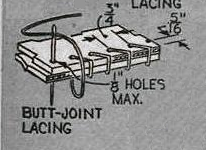
The canoe uses stick and glue plywood construction. This is how it is done:
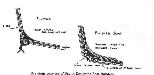 The main trick is to use copper wire as it can be removed when heated with a gas blow torch. You buy the fibre-glass tap, epoxy and epoxy filler (micro balloons) from a boating shop.
I hate fibre-glass so for this project I bought a roll of rather expensive dynel tape. Not as strong (about 40%) but sure nicer to work with.
Here is another method that I really like that I have only just discovered:
 (source: www.westsystem.com/ss/assets/project-images/_resampled/ResizedImage480262-09Dowel.jpg)
Some Canoe Construction Photos
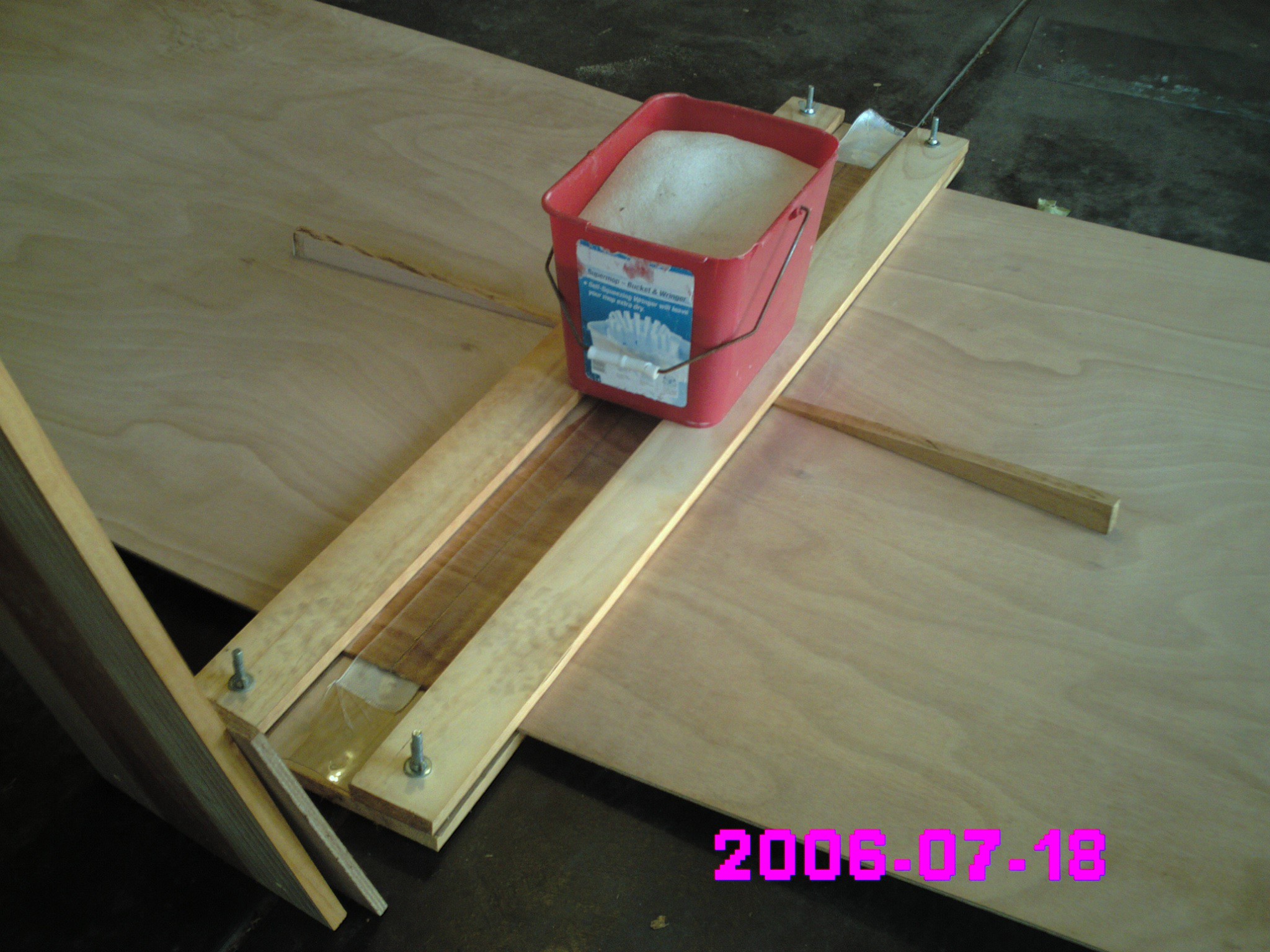
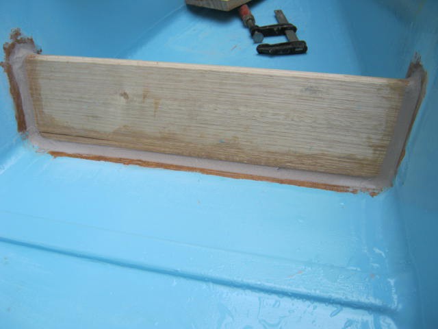
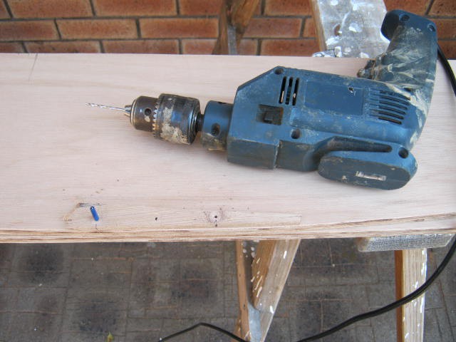
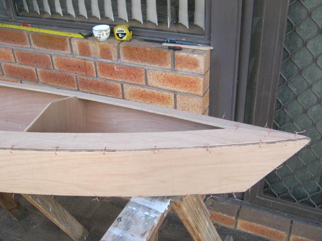
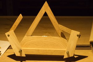
Here is the initial butt join of two sheets of 6 mm plywood. The wooden clamp just makes life a bit easier, but it is not the only way:
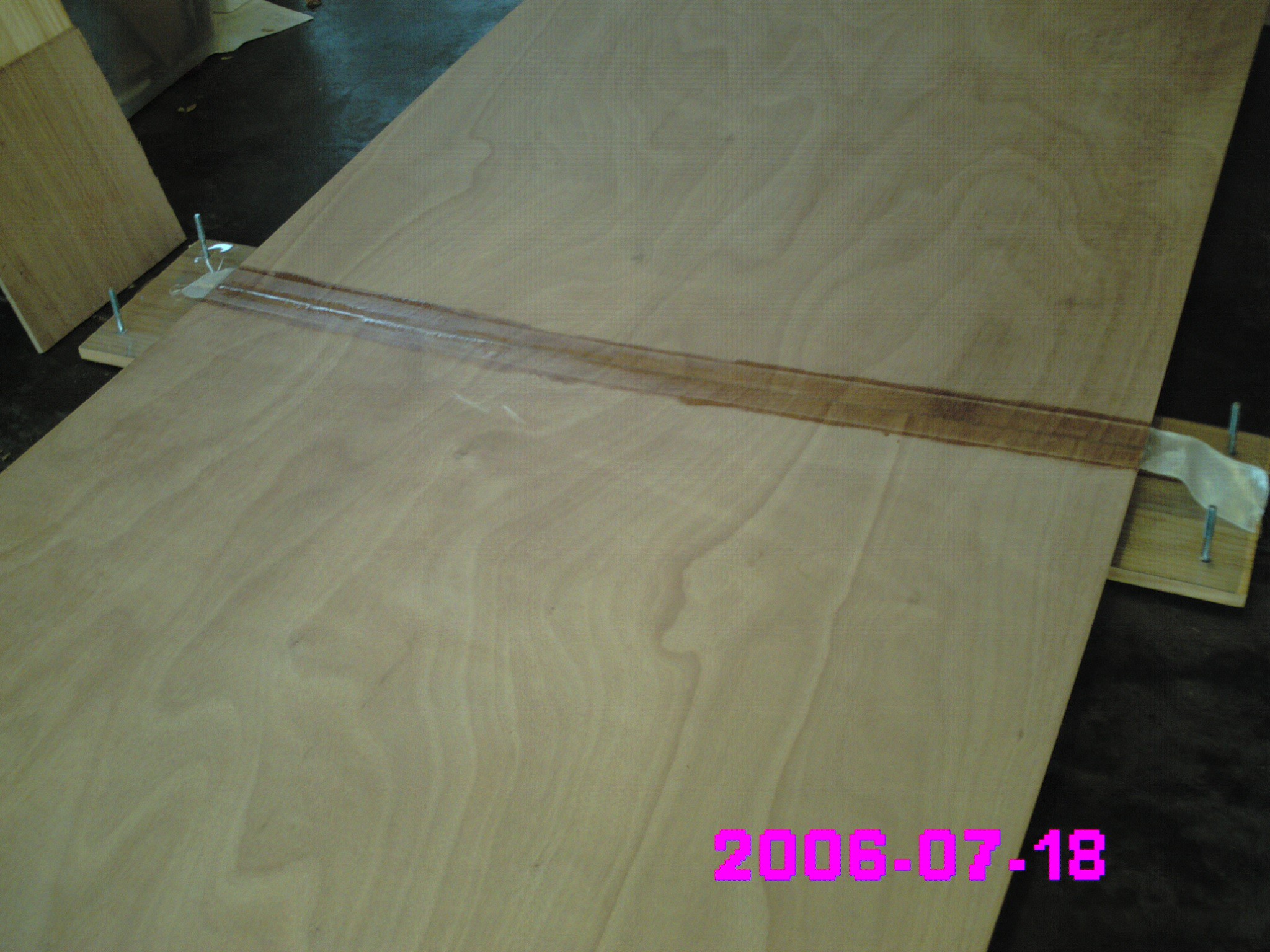
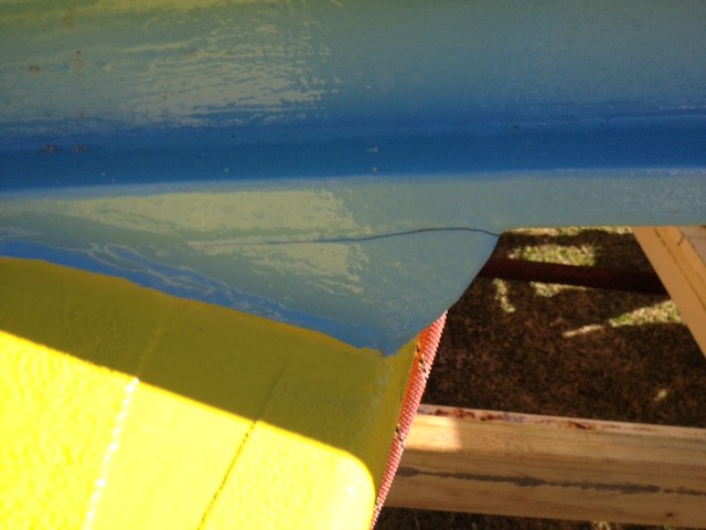
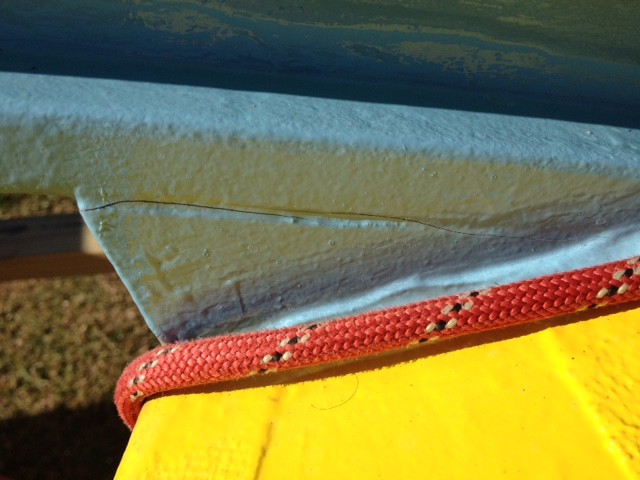
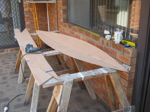
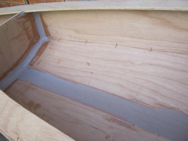
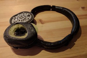
 Here is the finished join (before sanding off the sharp fibre-glass tap edges):
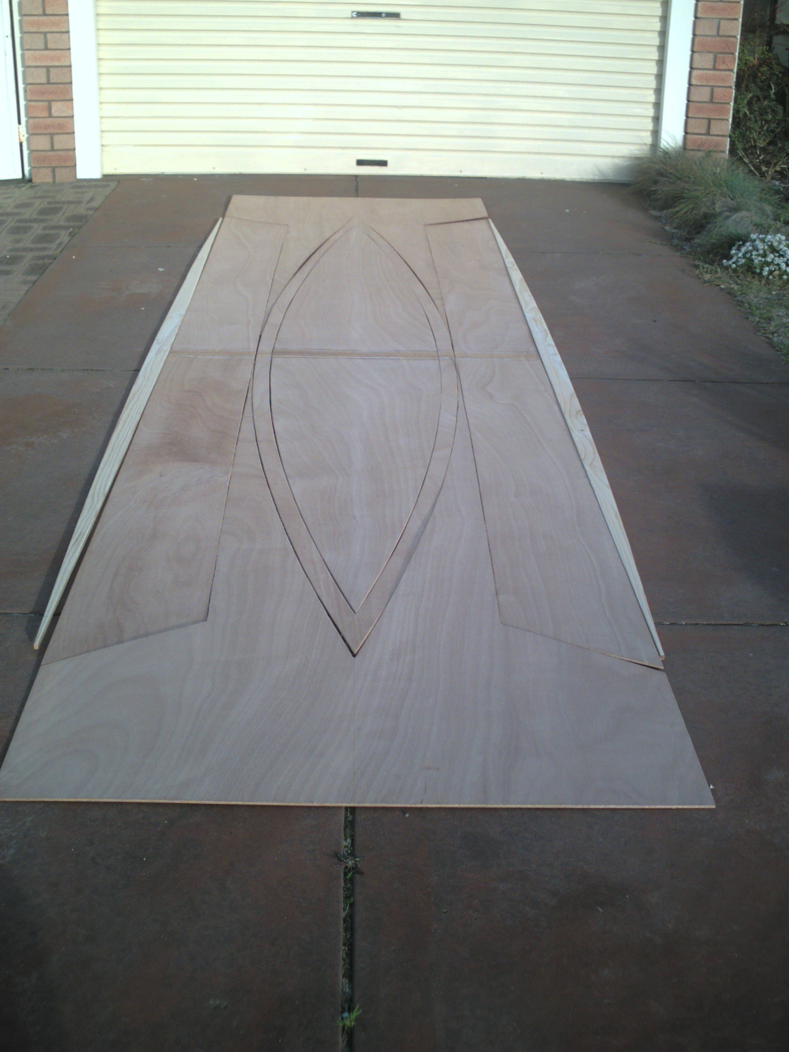
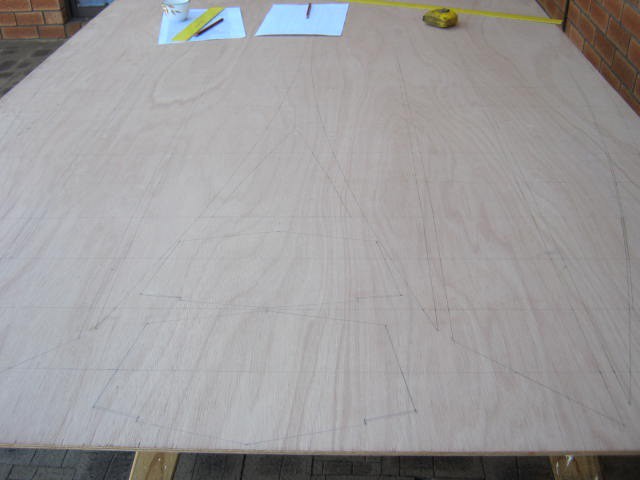
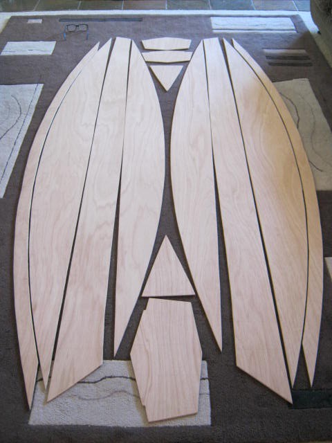
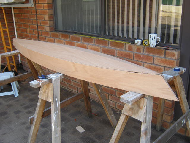
After sanding, marking and cutting out the pieces:
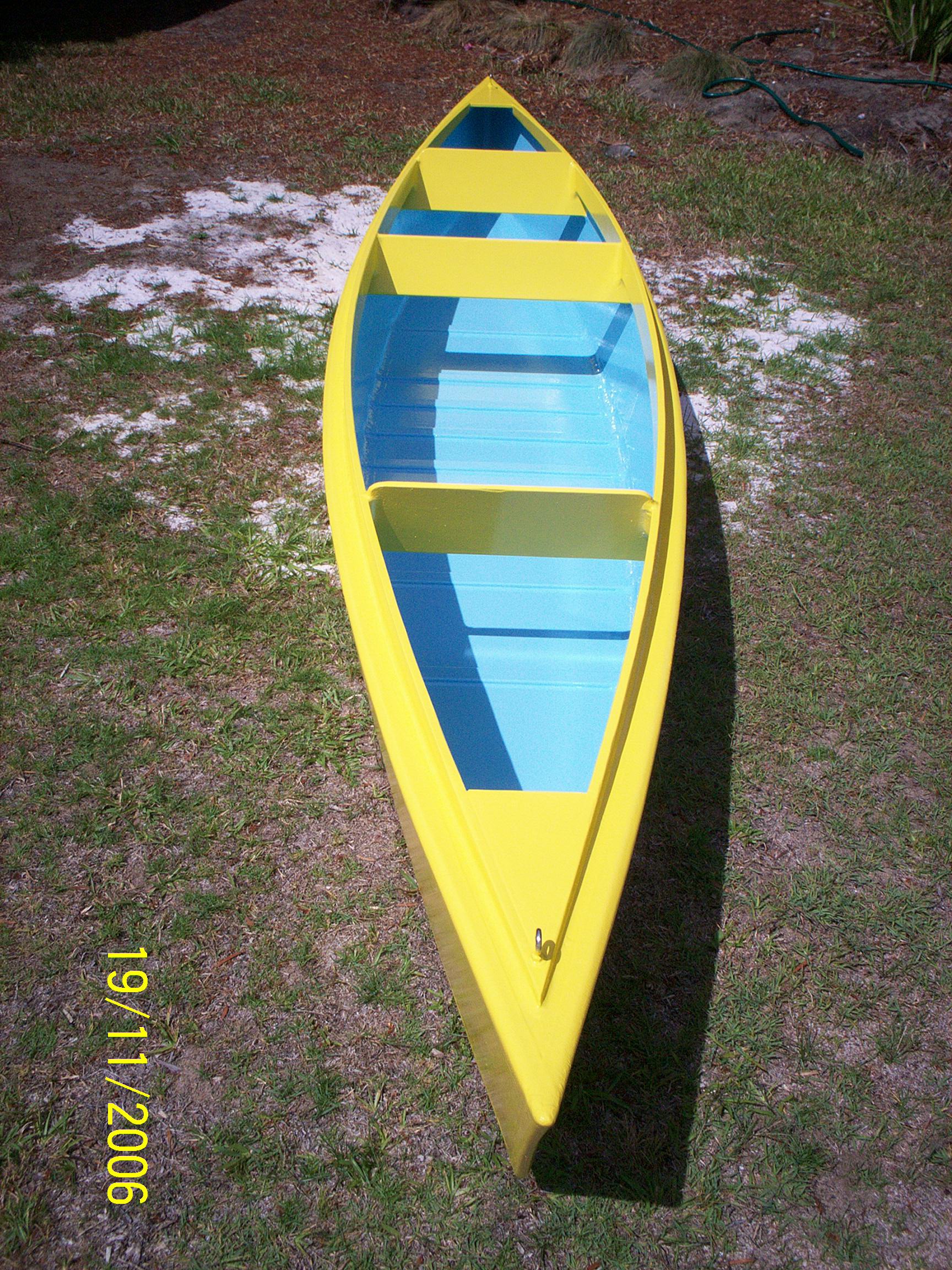
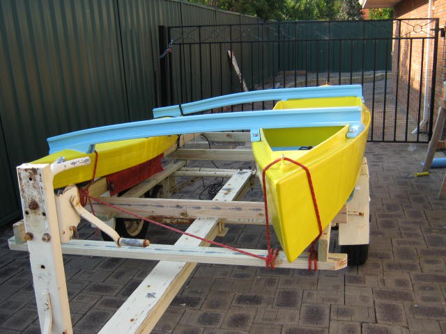
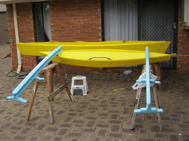
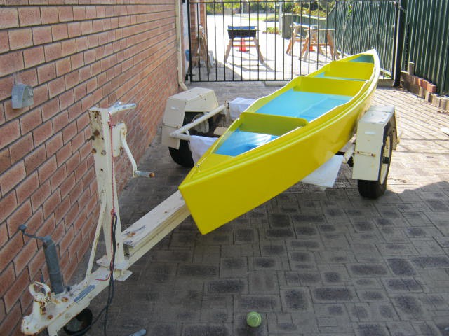
And the finally painted:
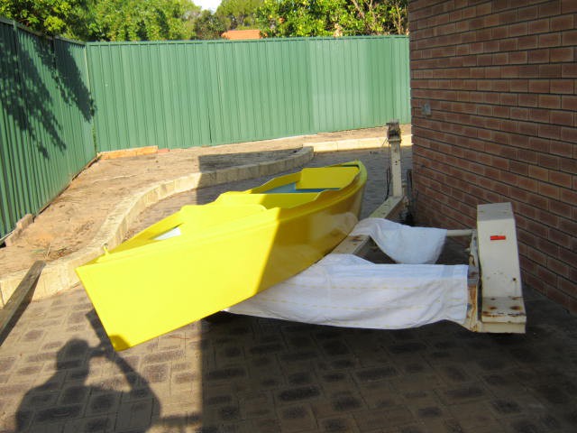
Design Flaws
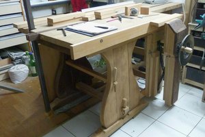
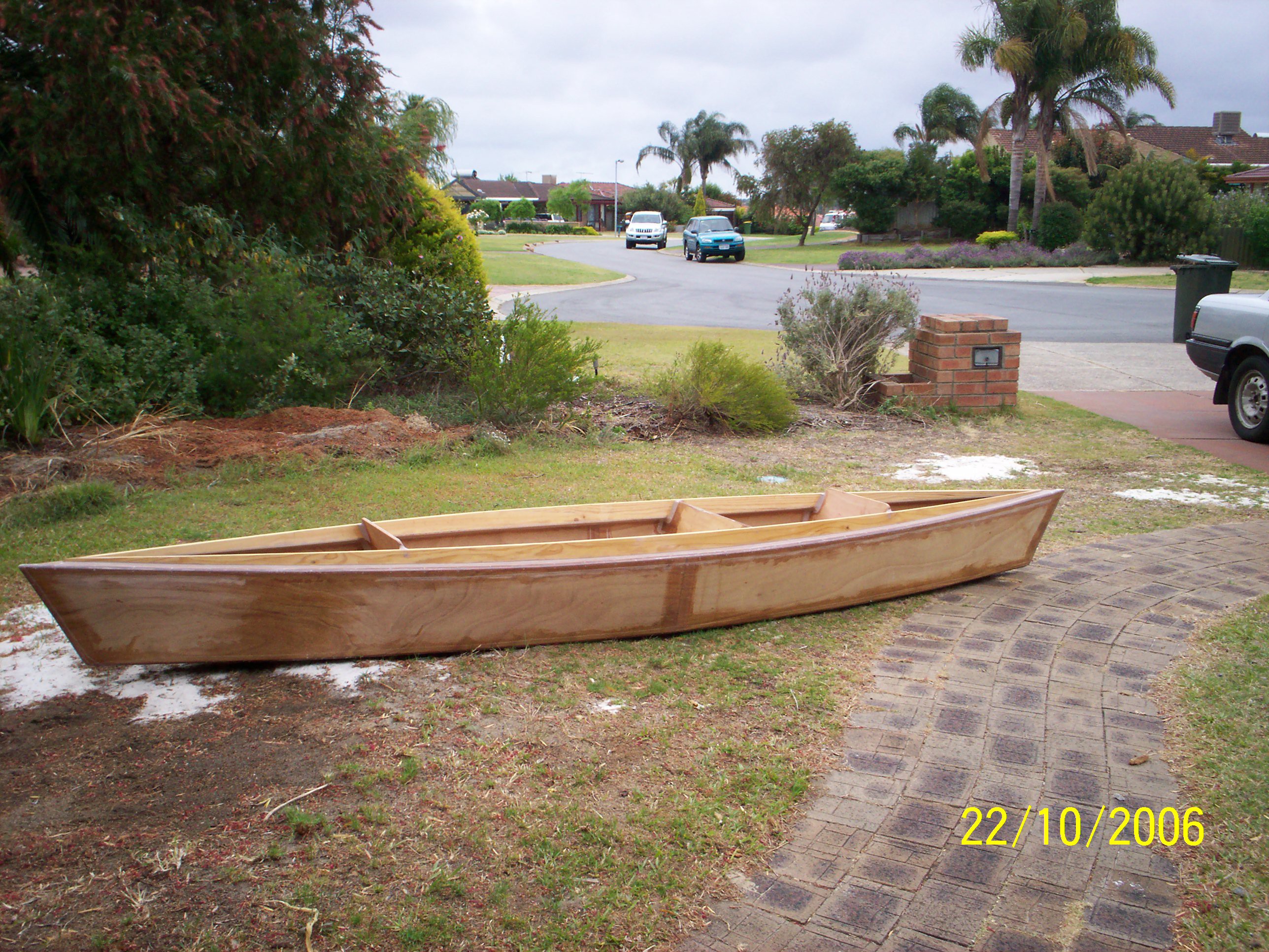
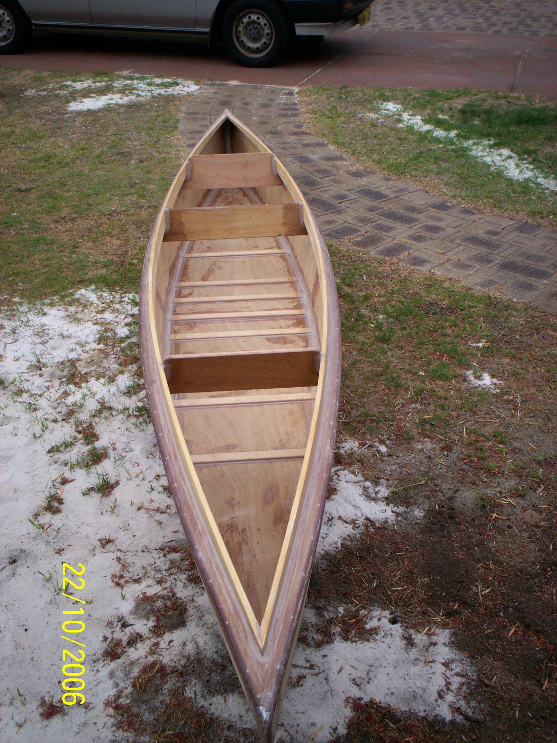
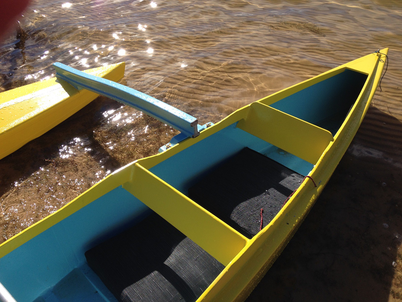
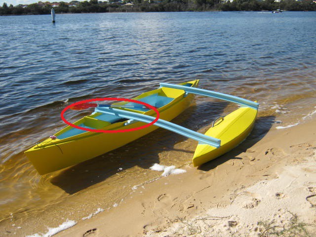
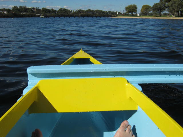
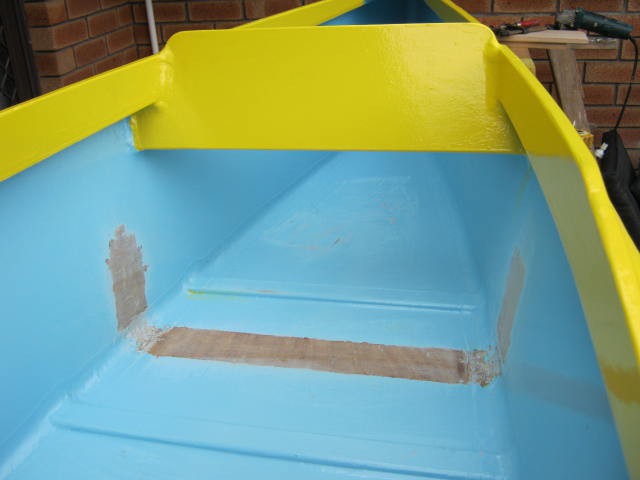
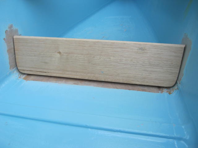
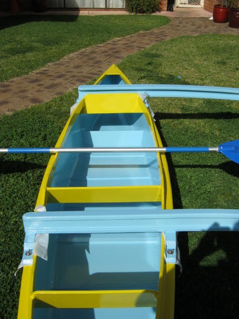
The first issue is that because the bottom of the canoe is wide, if you slide to one side you will tip! It would have been better to have a narrower sole that helps center your "seat" like this one:
The second issue that there is no foot rest to help move your weight around to maintain balance. Not ideal.
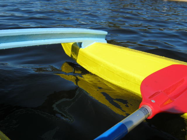
The final issue is that because canoe rides higher in the water (less than 2" displacement) it is less stable. You cannot use an elevated seat. Not ideal.
The Big Fix
Fixes:
- foot rests
- buoyancy tanks
- an elevated seat
- and an outrigger
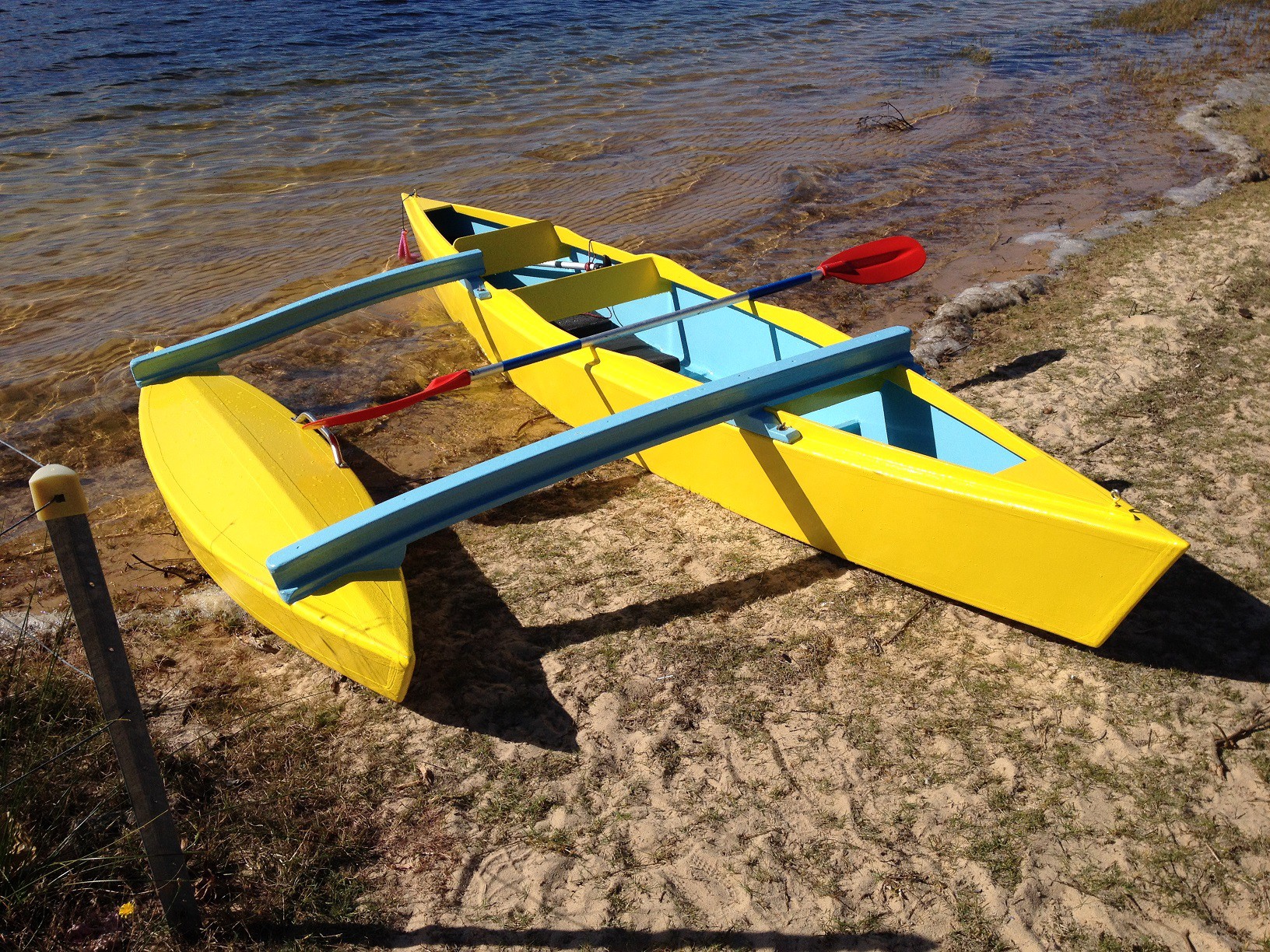
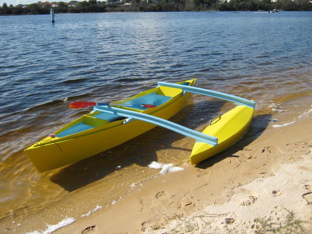
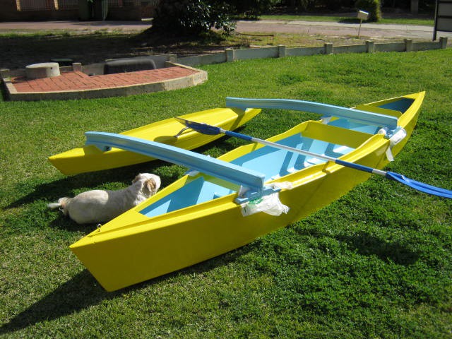
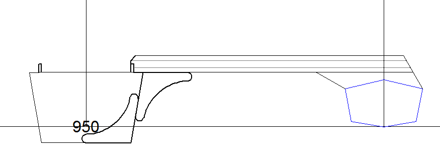
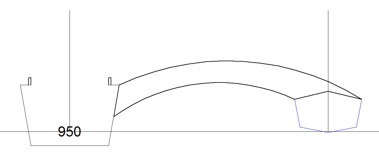
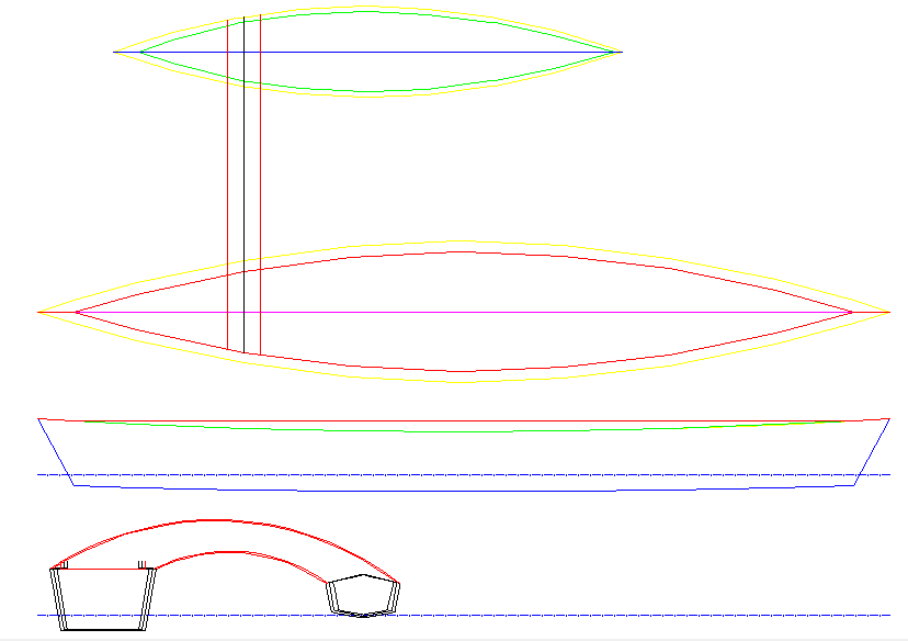
The Outrigger
I am going to use a 1/2 size mini-version of the canoe.
The bridge(s)/spar(s) will be detachable.
Here an image of a trimaran to give you an idea of what I have in mind (but less one outrigger):
 (source: www.duckworksbbs.com/plans/gumprecht/drifterfotos/drifter1.jpg)
AlanX

 He says "Give it a try - it is easier than you would think."
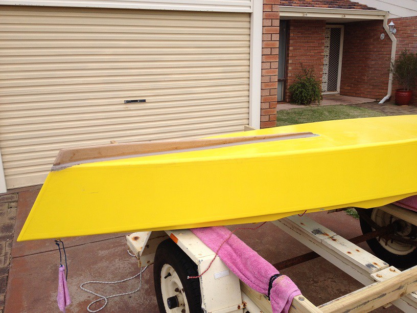

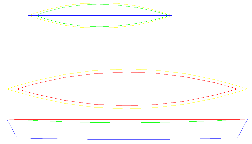

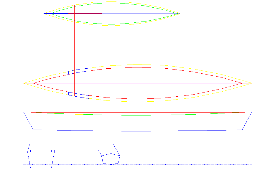


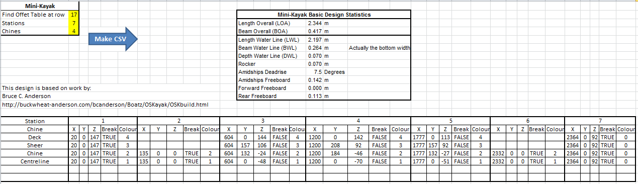
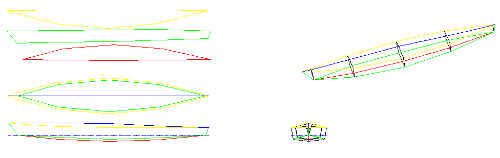
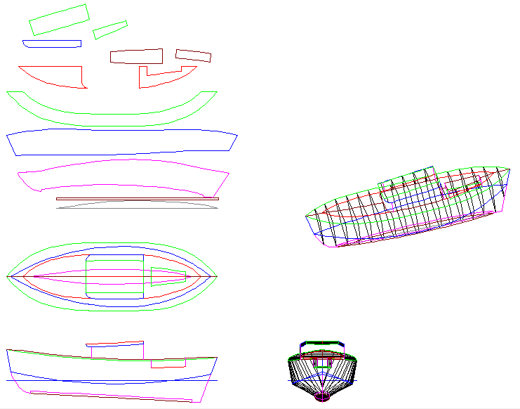


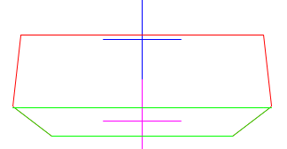
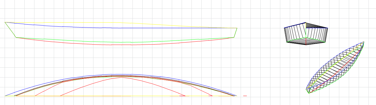
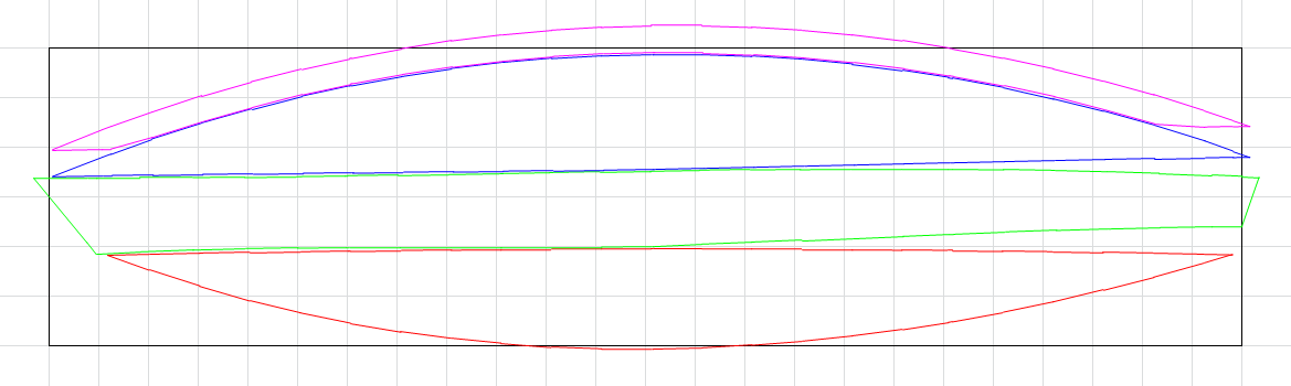 The magenta panel is a copy of the blue (top) panel but shifted 50 mm up and trimmed to the blue panel. Instead of using the blue (top) panel, the magenta panel is used instead. After all the inside seams are done, the blue (top) panel is glued/screwed over the magenta panel.

 [zit] Olivier Gade
 Magnus Selin