 agp.cooper
The Pontoon Bridge/Spar(s)
I have been playing with various options. The torsion maths says a single 6 mm plywood box (bridge) about 150 mm x 150 mm square will work (also 180 mm x 100 mm). The plywood can also be designed to take a curve. Otherwise a single 90 mm x 90 mm solid wood spar. Attaching the bridge/spar to the pontoon is straight forward. Attaching to the canoe is problematic. I am considering a wooden knee(s) (i.e. angle bracket) between the canoe outside and the bridge/spar.
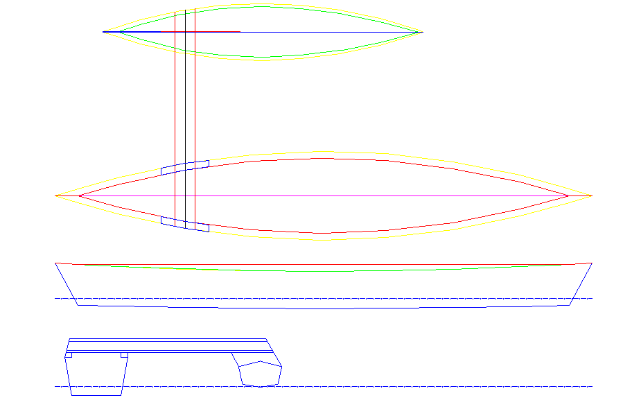
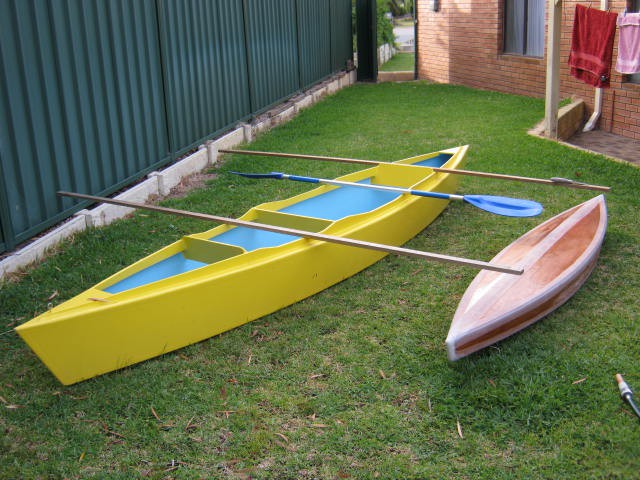
At the moment the bridge/spare is forward of the paddler (on the right) but I think it would be more out of the way on the left. The pontoon has to be clear of the paddle stroke which I calculate as about 1 m from the canoe sheer and 1.5m forward of the paddler:
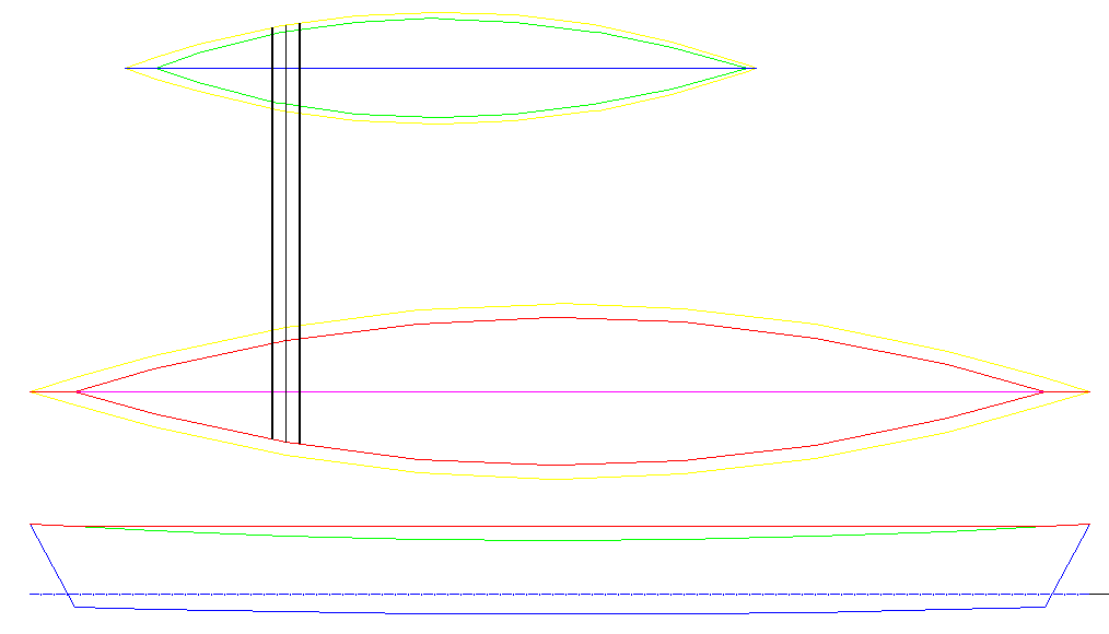
The knee(s) will require longitudinal reinforcement on the canoe inside/outside (perhaps another set of knees):
I will have to look at the option for the bridge/spar behind the paddler, and the lighter twin spar options as well.
Plywood Bridge
I had trouble finding suitable timber for the spars and knees. The plywood box is relative easy to make and would be attached with fibreglass tape. The box section is 180 mm wide and 100 mm deep with a minimum thickness of 6 mm. Likely I will use 18 mm thick pine for the side faces and 6mm plywood for the top and bottom:
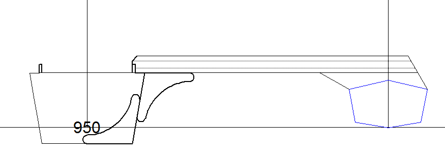
I am still having design problems with the plywood bridge. The main problem is the stress levels on the canoe hull (circled red below) are far too high:

Basically the bridge is like a can opener on the side of the canoe hull. I think I will have to go over the top like I did for the pontoon.
Basically I need to get the stresses directly to the outer skin.
I was a bit worried that I was over-designing the bridge so I checked out (reverse engineered) some designs on the Internet. The keyword here is "cross-beam" rather than bridge or spar. There are a number of designs (for bigger boats) that match my loading estimates after scaling.
I have been trying to rationalise why most of the design on the Internet don't have the stress problems that I have. I did notice that some designs did have pretty heavy duty saddles for the cross-beams. Eventually I noticed that the wale and skin thickness for most of the designs are pretty heavy duty! More than enough to just boat or lash on (with a cross-member and bulkhead backup).
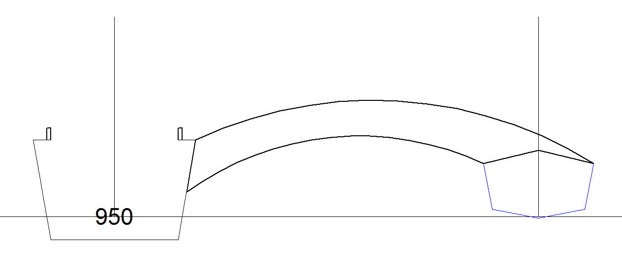
I have gone back to a hardwood cross-beam with a saddle for distributing the load:
I have been going around in circles with the cross-beam design. The problem is that I am trying to avoid the need to sanding the interior paint back to wood for epoxy joins. My fingers will not like me if I go down this path. Still the best option is to install a bulkhead or two to bolt the cross-beam to.
Checking the Internet the method of choice seams to be a heat gun and a scraper. I am not going back to chemical strippers (the modern stuff is pretty useless and the stuff is just as awful). Not keen to use screwed in frames/brackets. The heat gun may also work with removal of the copper tie wires. For A$65 worth a try. I have a bathroom ceiling that needs stripping anyway (I stripped it with paint stripper a few years ago and never again).
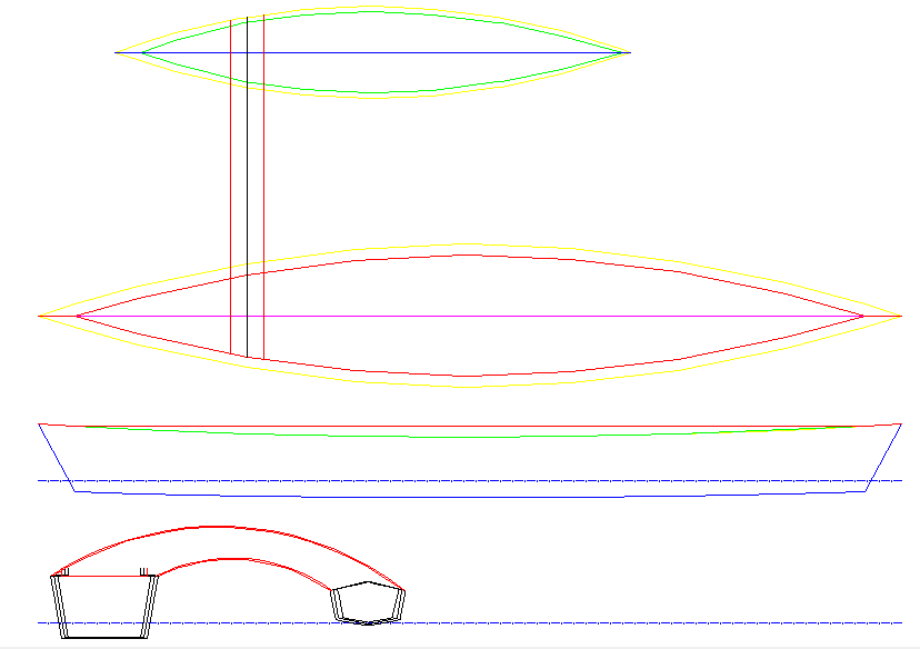
Here is the next proposal:

I have reduced the cross-beam to 100 mm x 64 mm using four 64 mm x 18 mm hardwood DAR. I have added two 12 mm plywood bulkheads to attach the cross-beam to the canoe. They are only 75% of the required design strength so rather than increase the thickness I will sheath them in fibre-glass.
I have looked at some designs on the Internet and the bulkhead seems to be the preferred method although I did see two half frames (similar to my orignal knee design).
The bulkhead options allows me to add a buoyancy tank (or two).
Before painting I have to attach the cross-beam and I am still struggling to determine the easiest way of doing this. I had a look at some timber at the hardware store yesterday. Not cheap! The simplest solution is a 90 mm x 90 mm solid pine but it really looks heavy compared to the pontoon!
The nominal load is 100 kg on the middle of the pontoon as the pontoon displaces 97 kg. I should have designed a thinner pontoon with less buoyancy! This results in bending moments and torsion. The minimum size solid wooden beam is 90 mm x 90 mm, the limiting factor is torsion (shear stress). If I use twin cross-beams (of solid wood) then the beams can be smaller (55 mm x 55 mm) and the torsion issue disappears. The Michael Storer Design looks good:
 (source: http://www.storerboatplans.com/Canoebits/canoeoutriggers.html)
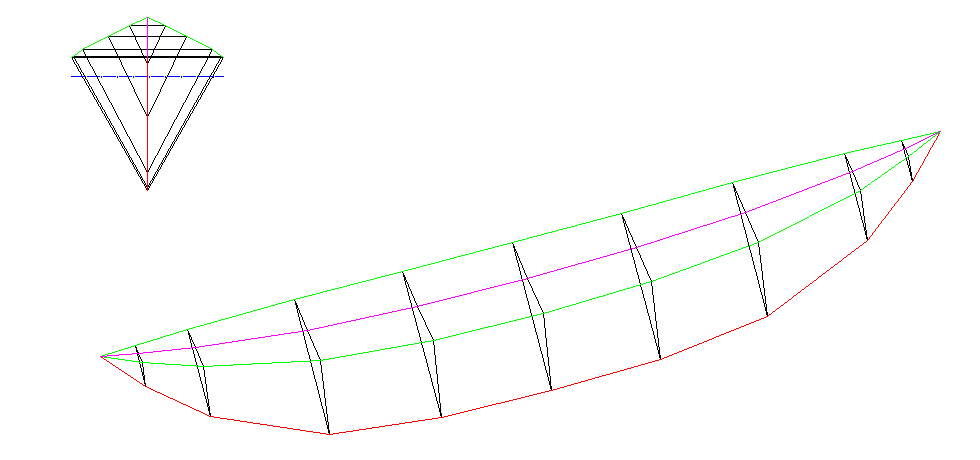
I while back I did design a "banana" pontoon as above:
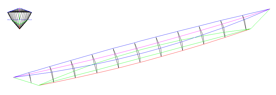
 But I prefer this one:
Something else I could have done was design the pylon for the cross-beam in the hull design.
Anyway, here is an I-beam for a twin cross beam:
The flanges (the outside edges) are 42 mm x 19 mm hardwood DAR and the web (the inside) is cut out of a 90 mm x 19 mm hardwood DAR (1.8 m long). The flanges will need to soaked in boiling water to take the curve. The cross-beams will sit on a saddle on the canoe (not shown).
Updated Twin "I" Cross-Beam
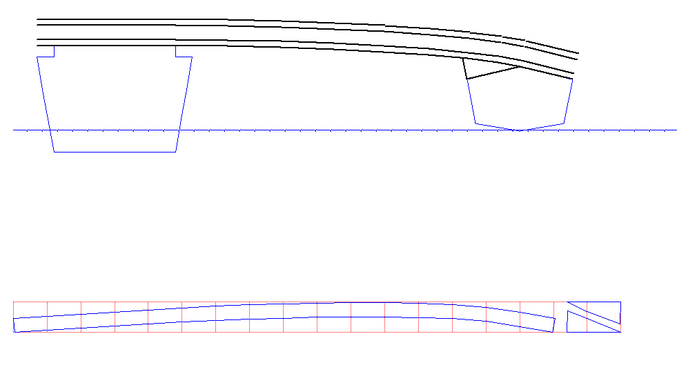
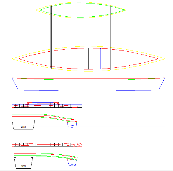
Here is a design with the new cross-beam locations considered:
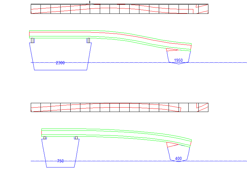
Looks pretty doable.
Taping the Seams
This time I used Dynel Tape instead of fiber-glass tape. One good thing about fiber-glass tape is that it almost invisible when epoxied, no so with Dynel:
Al close up:
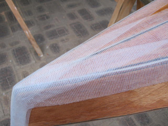
It is also thicker. But no problem it will be painted anyway.
The epoxy mix includes wood preservative this time around and I have coated the plywood.
Next is to trim the tape at the ends and then tape the top of the pontoon.
I-Beam Calculations
Here are the I-Beam calculations:
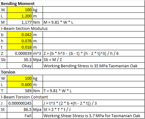
A single cross-beam is strong enough in bending but fails in torsion. We can solve this by (1) adding a second cross-beam to remove the torsion or (2) increasing the size of the beam to meet the torsion stress limits. The cross-beam is just too big for case (2).
Mock-up
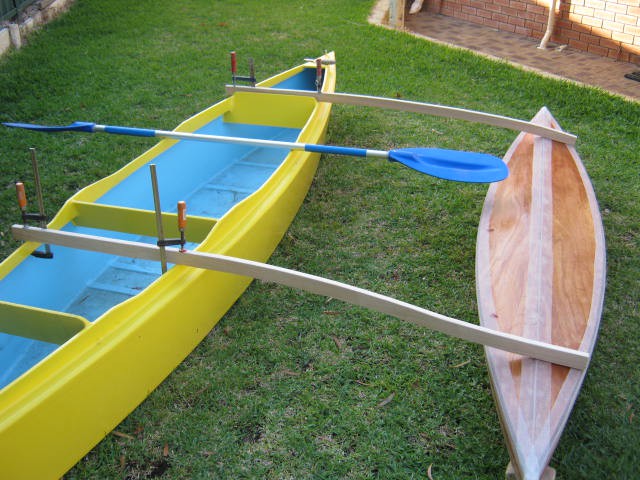
Here is a muck up of the out-rigger. After trying it out (lawn paddling?) I moved the cross-beams aft 250 mm. The 1.2 m centre-line offset was okay but I bumped out an extra 50 mm.
Updated the design:
I am going to either use 90 mm wide DAR (bottom) or laminate 42 mm x 19 mm DAR to the width I need (top):

Finally I exported the shapes to excel for lofting.
I will epoxy glue the beams to the pontoon but also use fibre-glass to reinforce (i.e. spread the load of) the join.
Cross-Beam Webs Cut Out
Cut out the webs of the two cross-beams. Here is the lofting of the forward beam:
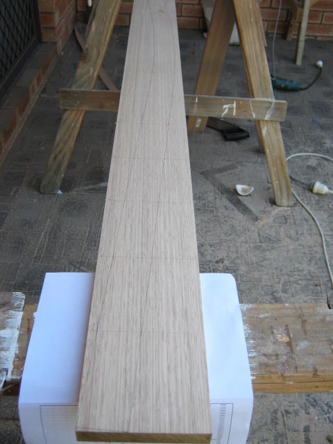
Another hardware store had both 90 mm and 110 mm wide planks so no need to laminate a wider plank. Mock fitted them to the canoe:
Checked the sideways cross-beam strength and decided to use 65 mm wide flanges (rather than 42 mm).
The bending radius for the forward cross-beam is about 2.5 m and the rear cross-beam is about 3.0 m. Very unlikely I can bend Tasmanian Oak along the grain that much (e.g. 19 mm plywood along the face has a bending radius of 6.7 m) without steaming or laminating thinner strips (i.e. 9 mm). I will have to see what I can find.
Steam Bending
That was not hard, a wallpaper steamer (A$100):
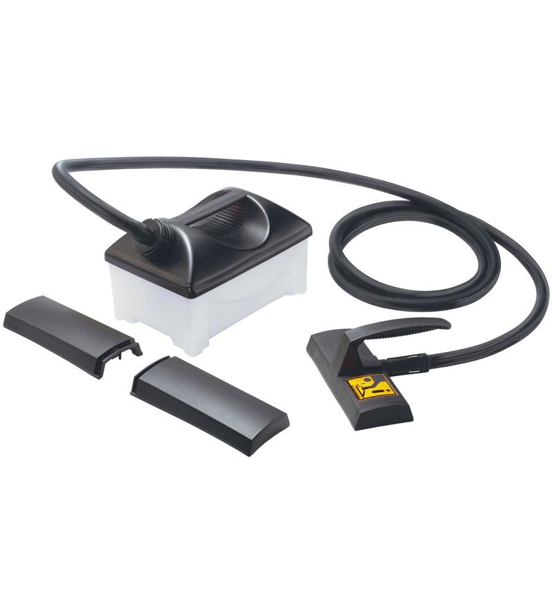
Add 4 litres of water (80 minutes of steam), plug it in (2000W) and let her rip. Just need a simple steam box. I think I only need something that can take two 65 mm x 19 mm DAR and steam a length of up to 1.2 m. A length of 100 mm diameter PVC pipe?
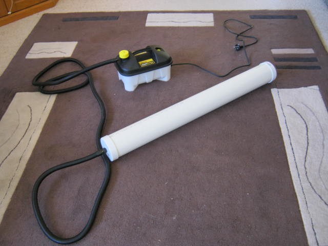
Well here it is, a 1 m length of 100 mm heavy duty PVC pipe, two end caps and the wallpaper steamer (about A$115 all up):
I cut down one of the steam "cups" provided and bolted it inside one of the end cap:
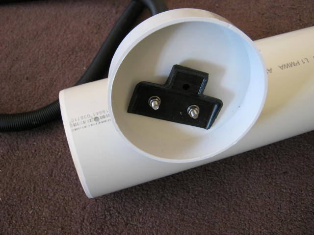
I also drilled two small holes at each end to let the water out (and to stop the end caps from being blown off. I can replace the 1 m tube with a longer one at anytime. About the only other thing that could be done is to add wooden dowels across the tube to suspend the wood. A 1 m tube will work as I only have to bend one half of the wood for the cross-beam.
Here is the steamer in action:
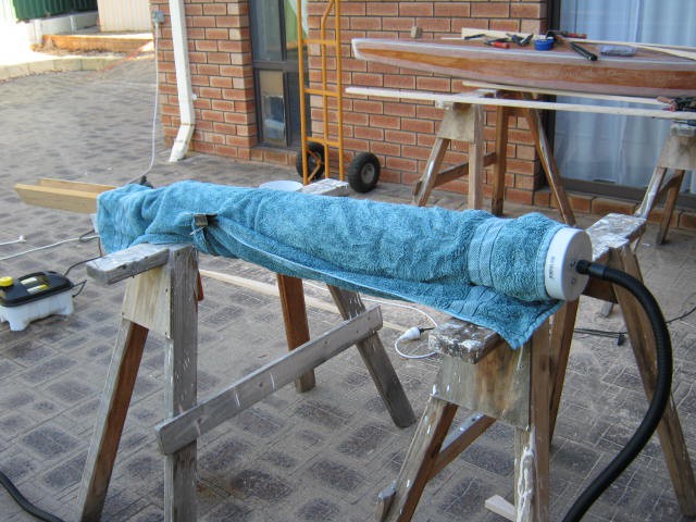
And here is the first cross-beam (note how the tube has basically lost its shape):
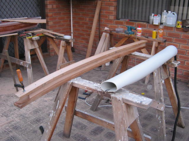
PVC tube is pretty hopeless in this application. I will have to build a wooden box.
The steamer however worked fine. With hot water it took about 5 minutes to start boiling and the steam box took another 5 minutes to blow a full head of steam.
The idea of clamp, check/adjust, drill and screw is just too slow. It took 15 minutes and by then the wood had cooled. Still I only need to epoxy glue the web to the flanges and the cross beam is done. The beam itself is has a pretty solid feel.
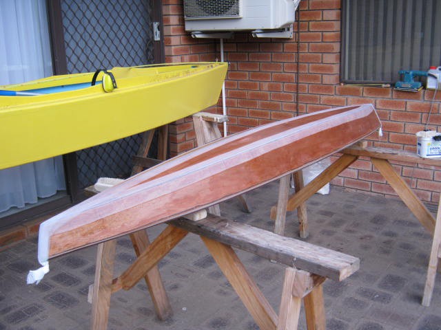
First Beam Done
Well done excluding finishing. Here it is:
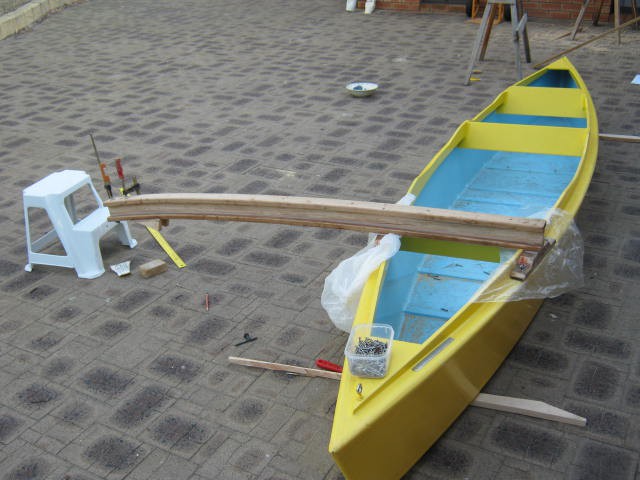
The plastic is to stop the epoxy gluing the beam to the canoe. The saddle is glued and screwed to the beam and bolted to the canoe deck/chine. Here is another view:
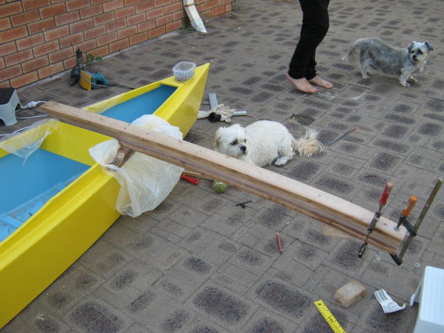
Here is the rear cross-beam:
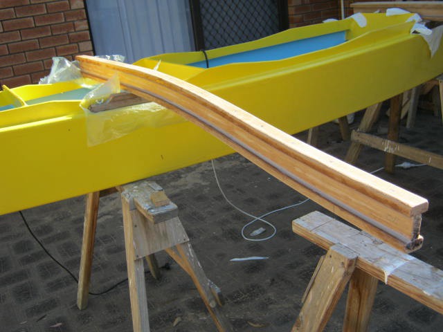
You may be wondering how the cross-beam is connected to the saddle? It is glued:
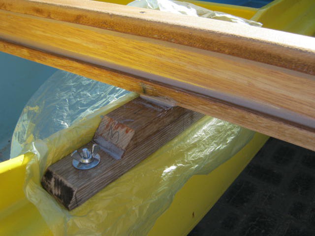
Now it sure looks like a weak spot! The limiting factor is the strength of the wood in tension perpendicular to the grain (not the glue). This is not usually specified for wood because that say "don't do it!". Anyway I have done it so is it strong enough? An estimate for the tensile strength perpendicular to the grain is 1/10 to 1/20 of the tension parallel to the grain. So I will use 1/15 as an estimate. Here are my calculations:
| Glued Cross-Beam Strength Estimate | Value | Units | Comment |
| Parallel | 60 | MPa | Ultimate Tensile Strength Estimate |
| Perpendicular | 4.0 | MPa | Approx. 1/15 |
| Width | 0.042 | m | |
| Breath | 0.042 | m | |
| Area | 0.00176 | m^2 | |
| Ultimate Load | 7056 | N | |
| Spacing (gunwale to gunwale) | 0.5 | m | |
| Lever Arm (gunwale to pontoon centre) | 1.0 | m | |
| Maximum Load (at pontoon) | 3528 | N | |
| Safety Factor | 3 | Very uncertain strength parameter | |
| Working Load (at pontoon) | 1176 | N | |
| Working Load (at pontoon) | 120 | kg | Okay! |
So it seems to be strong enough. Maybe I will add some fibre-glass tape for insurance.
Attaching the Pontoon
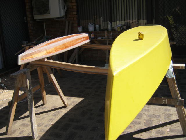
I turned the canoe upside down so that gravity would settle the pontoon onto the cross-beams with minimal stress (i.e. twist):
A view of one of the glue joins:
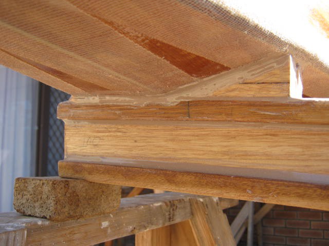
The area of the glue join is five times the saddle so no need for any strength calculations.
---
If I was doing this again I would have installed two long bolts sticking out of the pontoon. That way I could just bolt the cross-beam to the pontoon.
---
Some remedial epoxy work, a good sanding, a coat of epoxy/preservative and a paint job remains.
AlanX
Discussions
Become a Hackaday.io Member
Create an account to leave a comment. Already have an account? Log In.