 Ramón Calvo
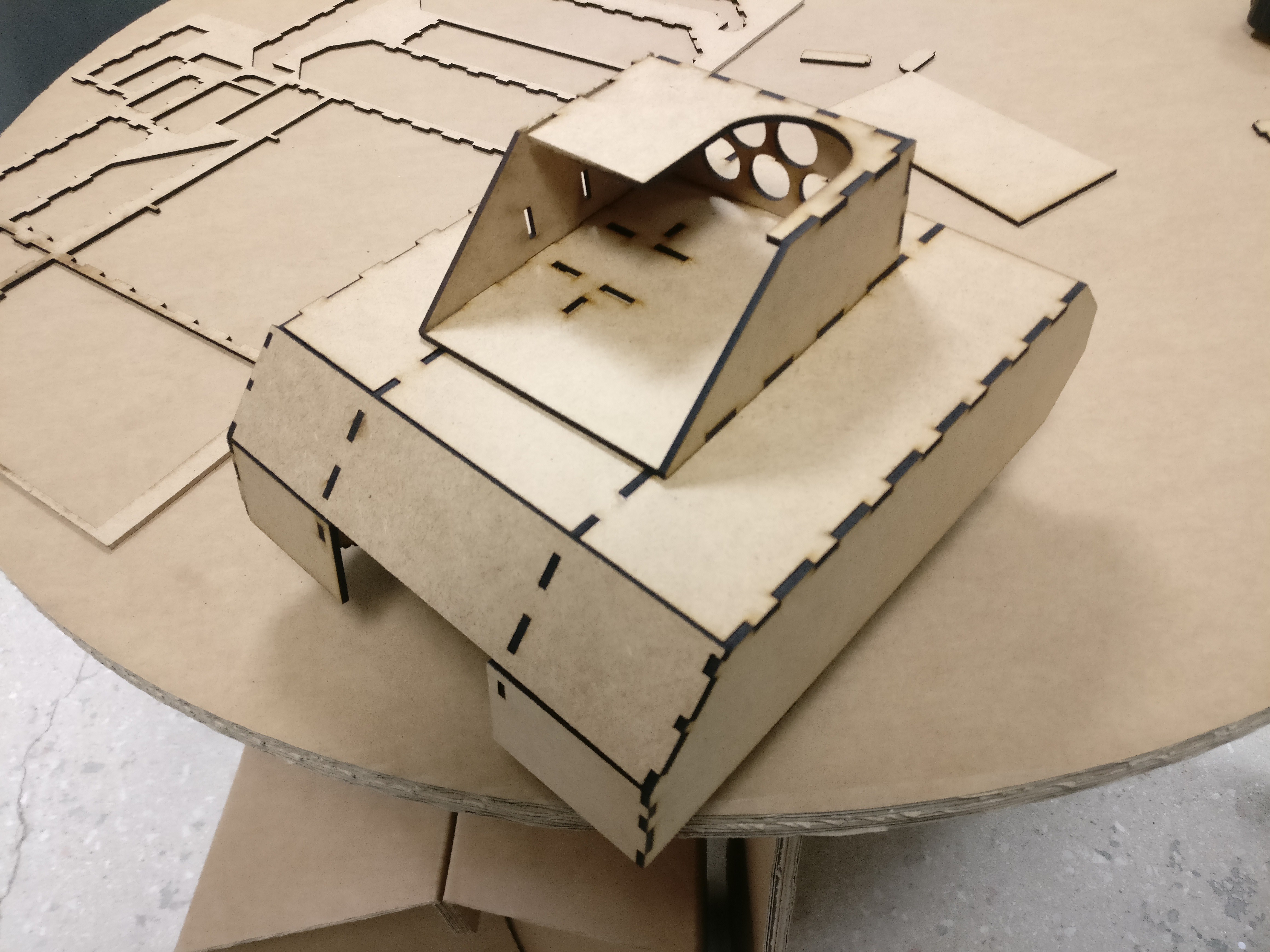
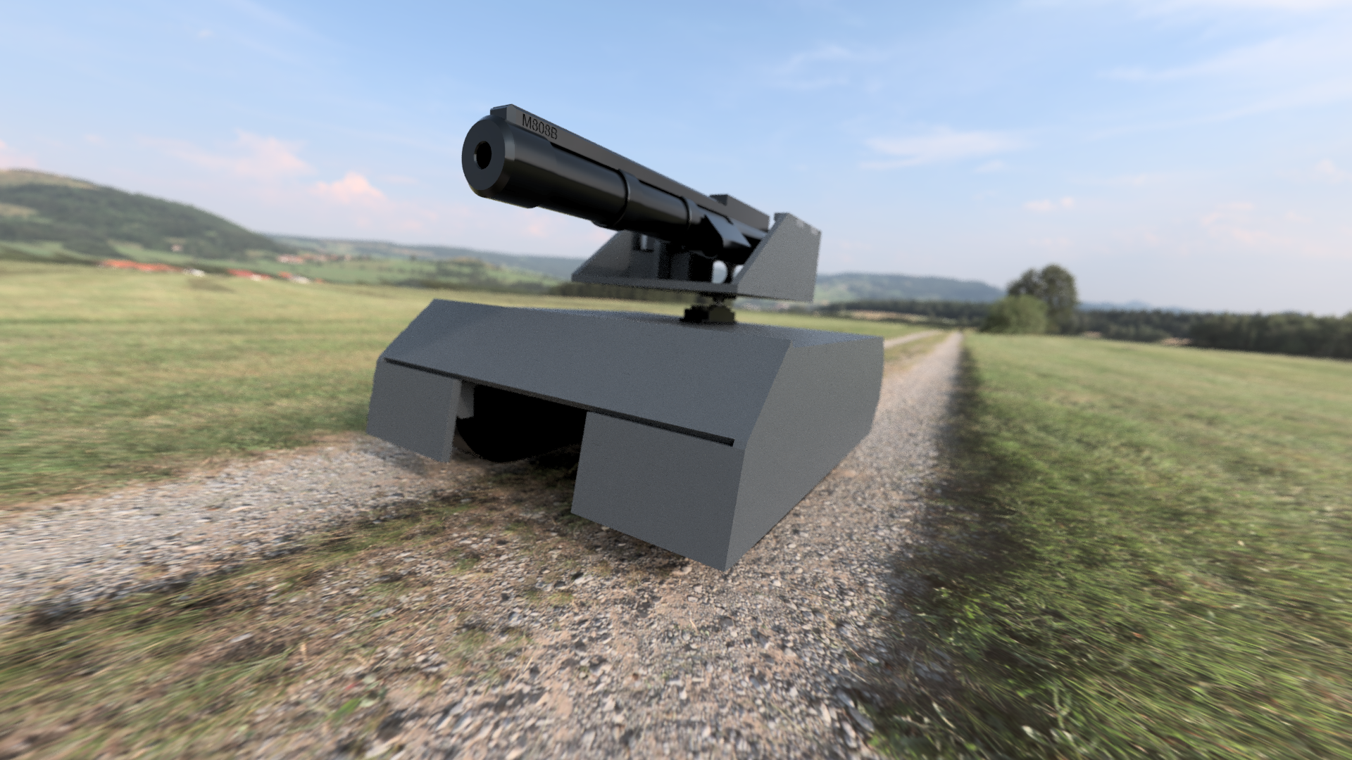
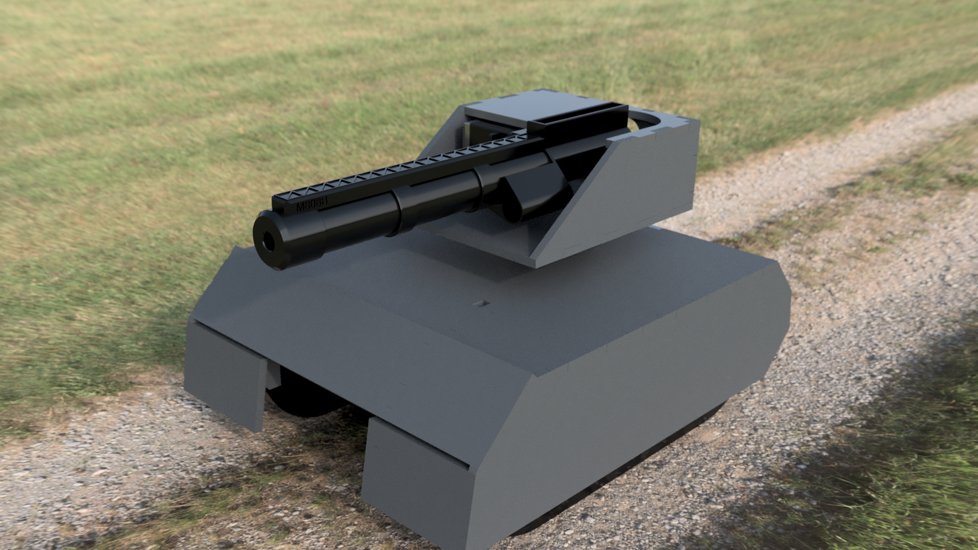
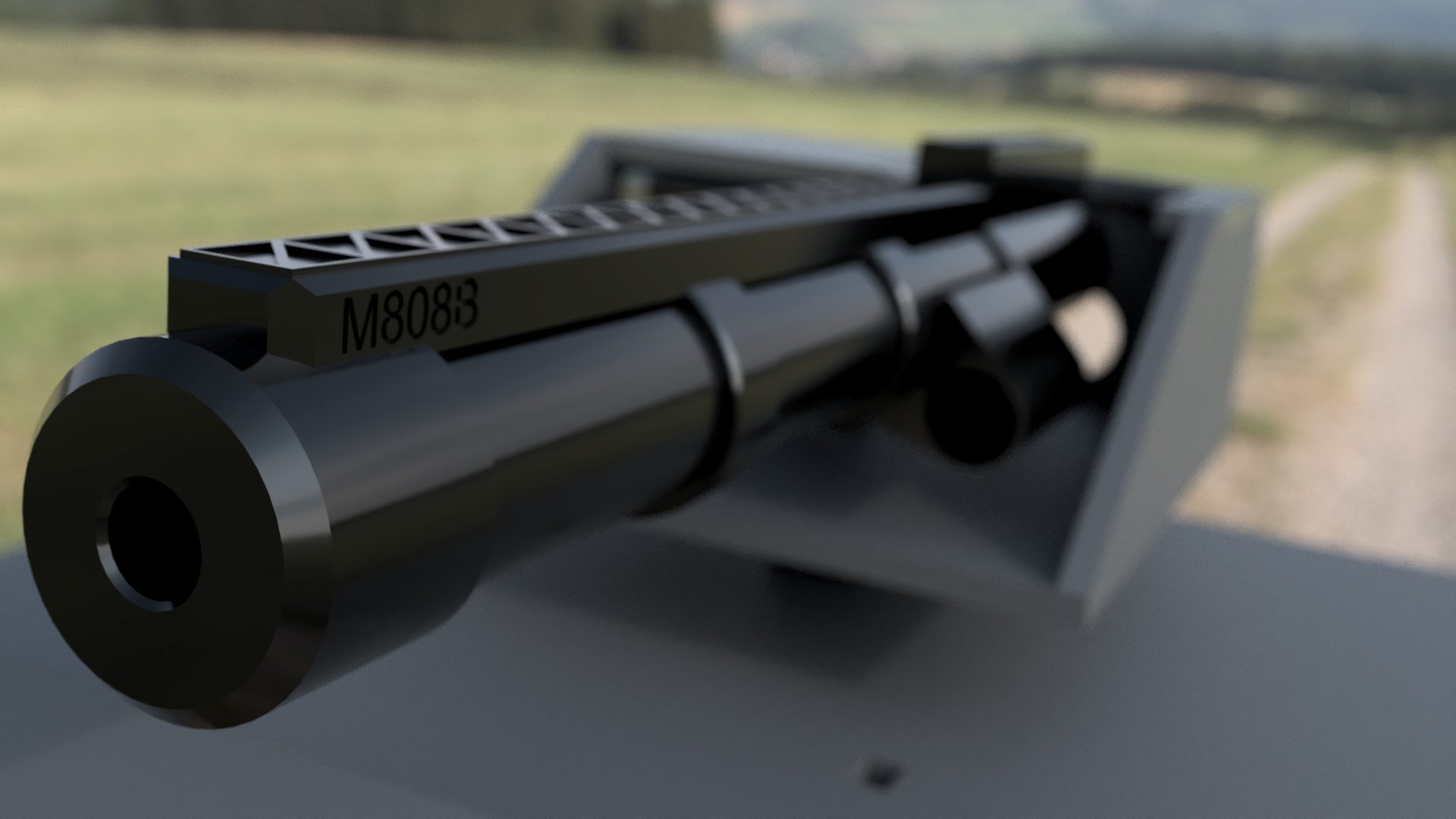
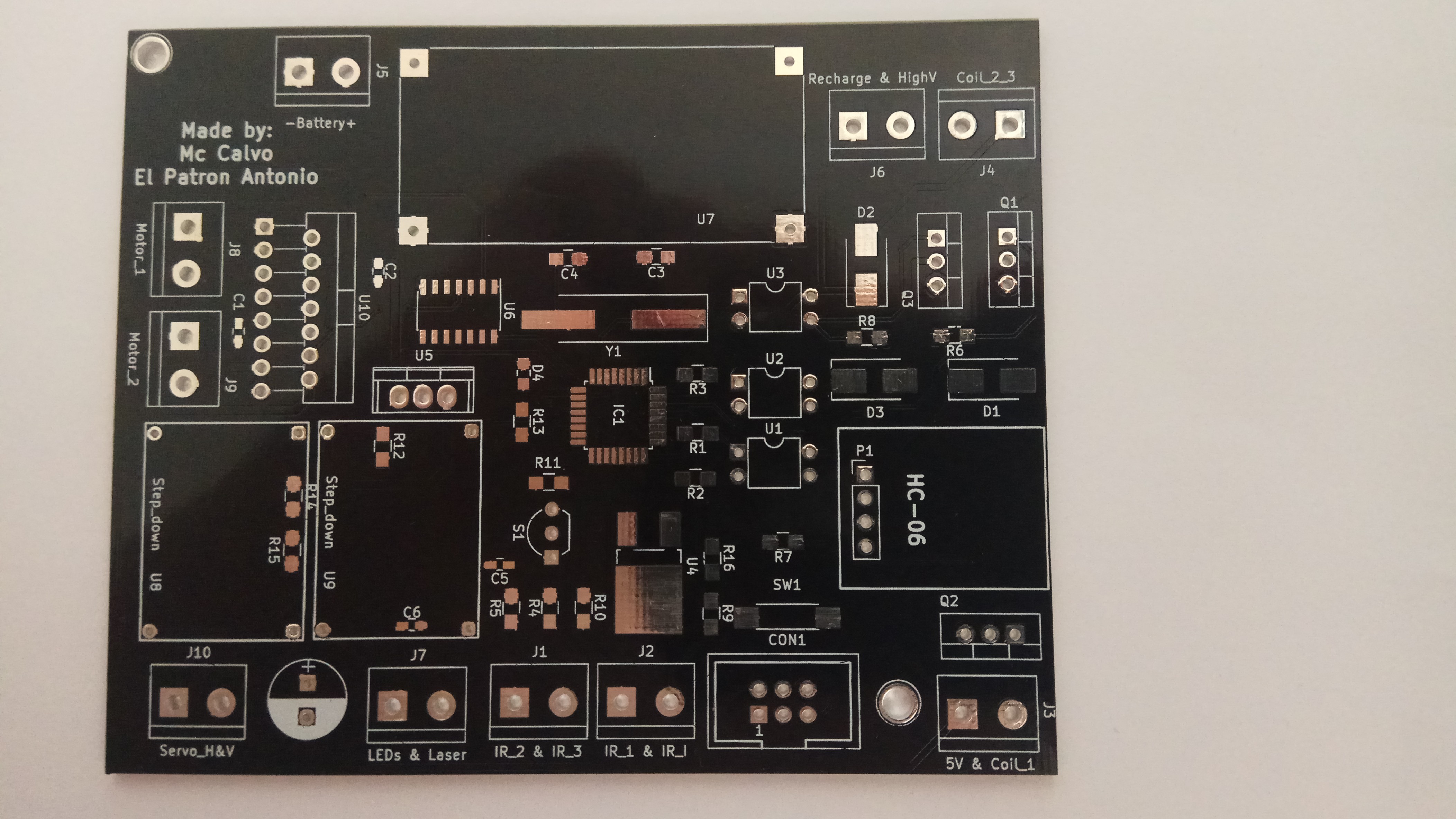
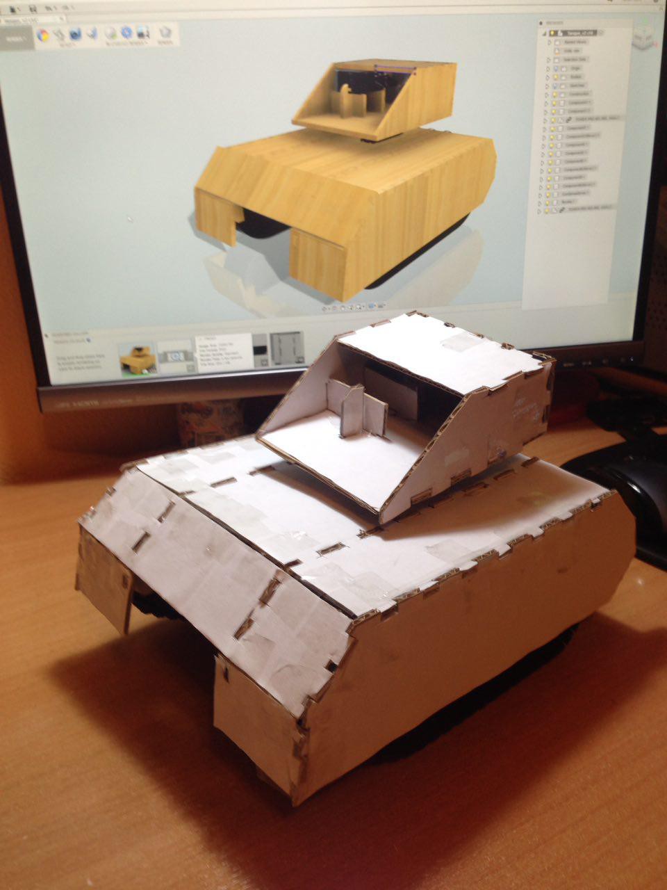
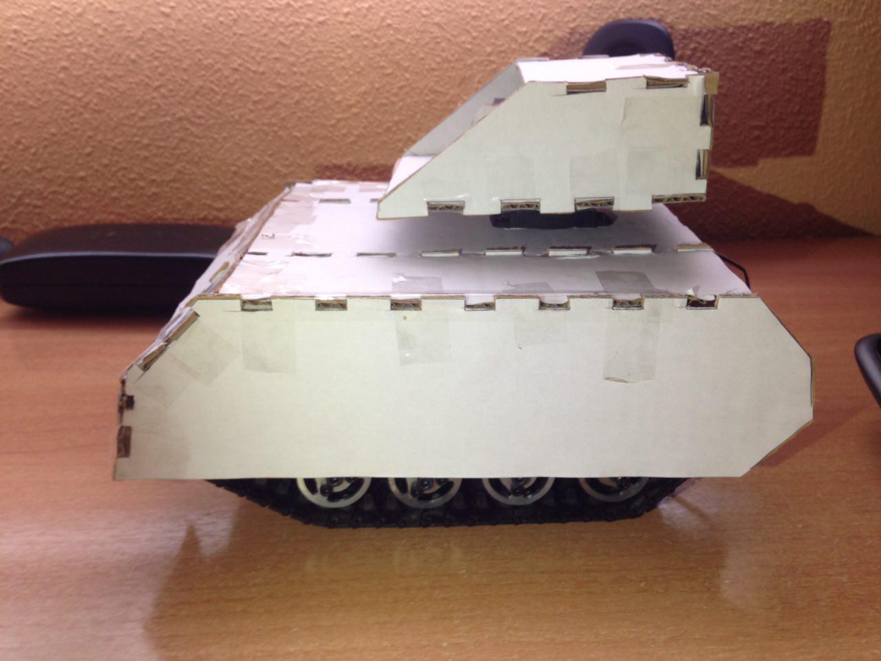
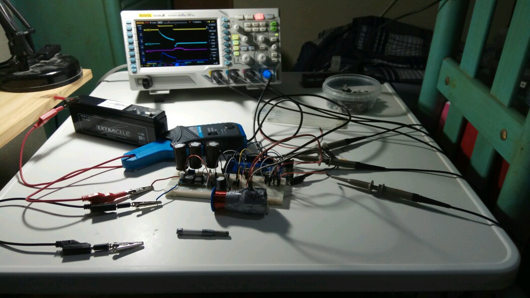
To do this project we divided the work in hardware and software. Antonio will do all the harware related stuff (designing the circuit, testing the coilgun, ...) and I'll write all the software (both the microcontroller and Android app), design the 3D model of the cannon and the tank itself and mount it.
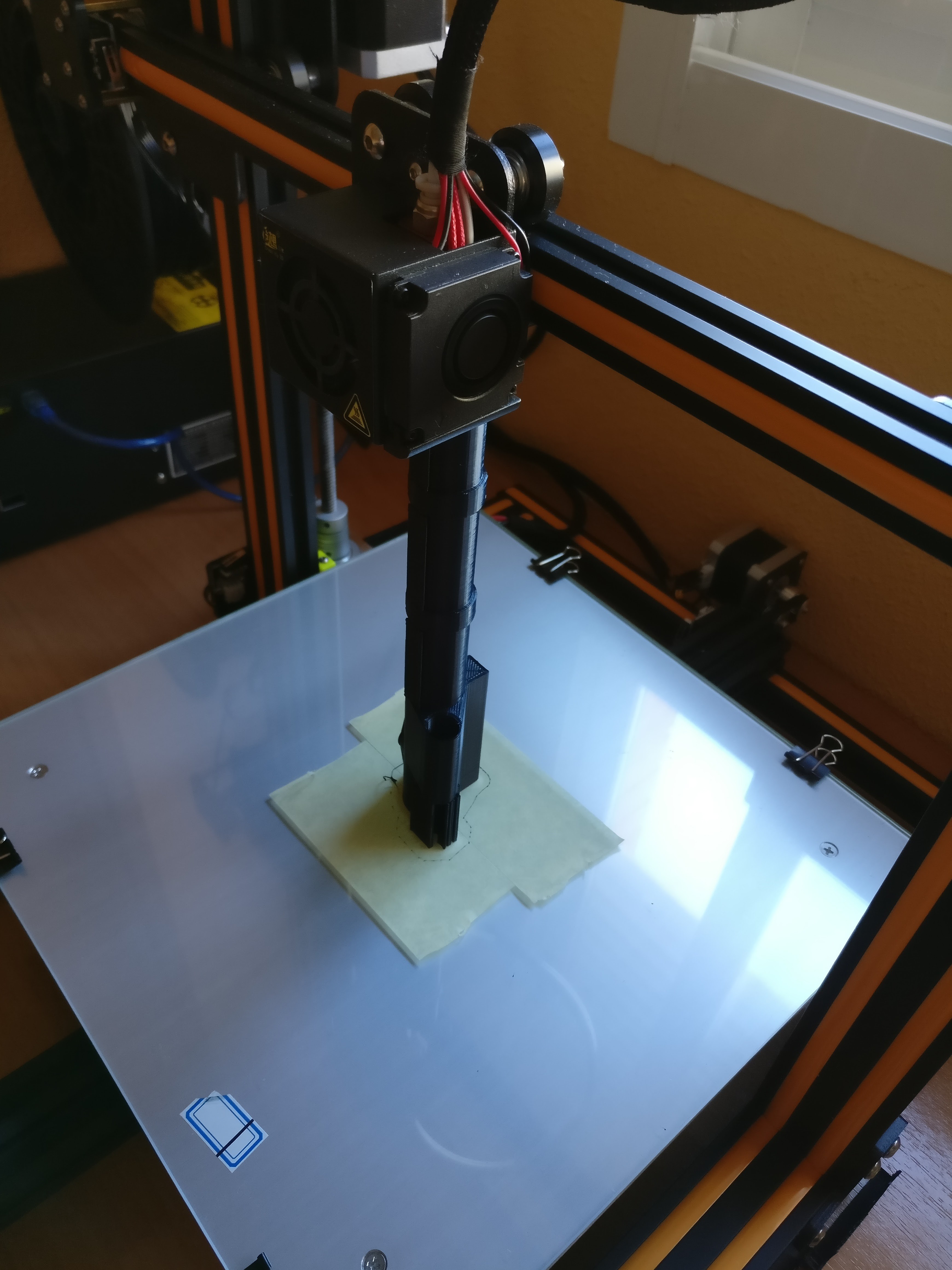
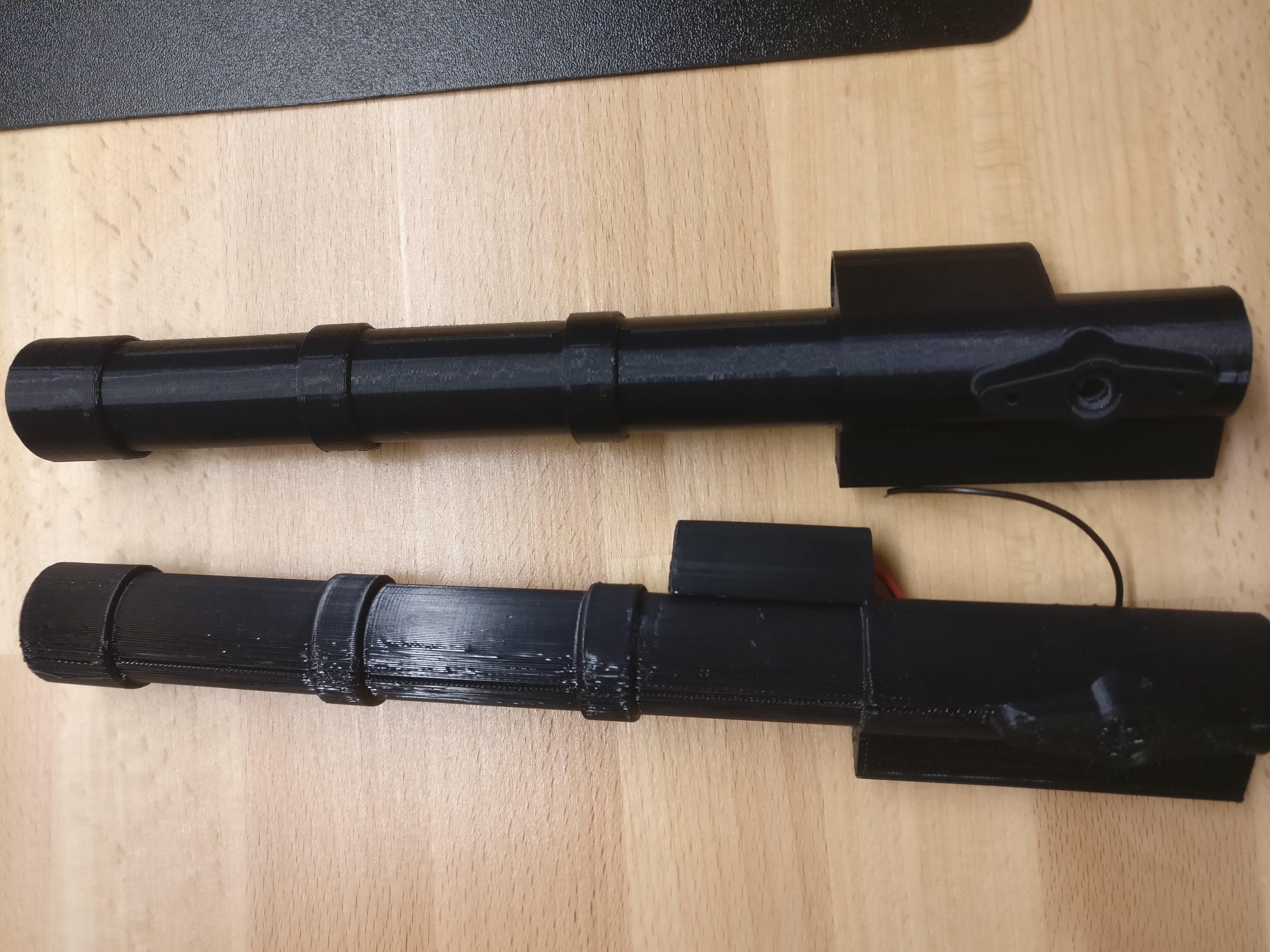
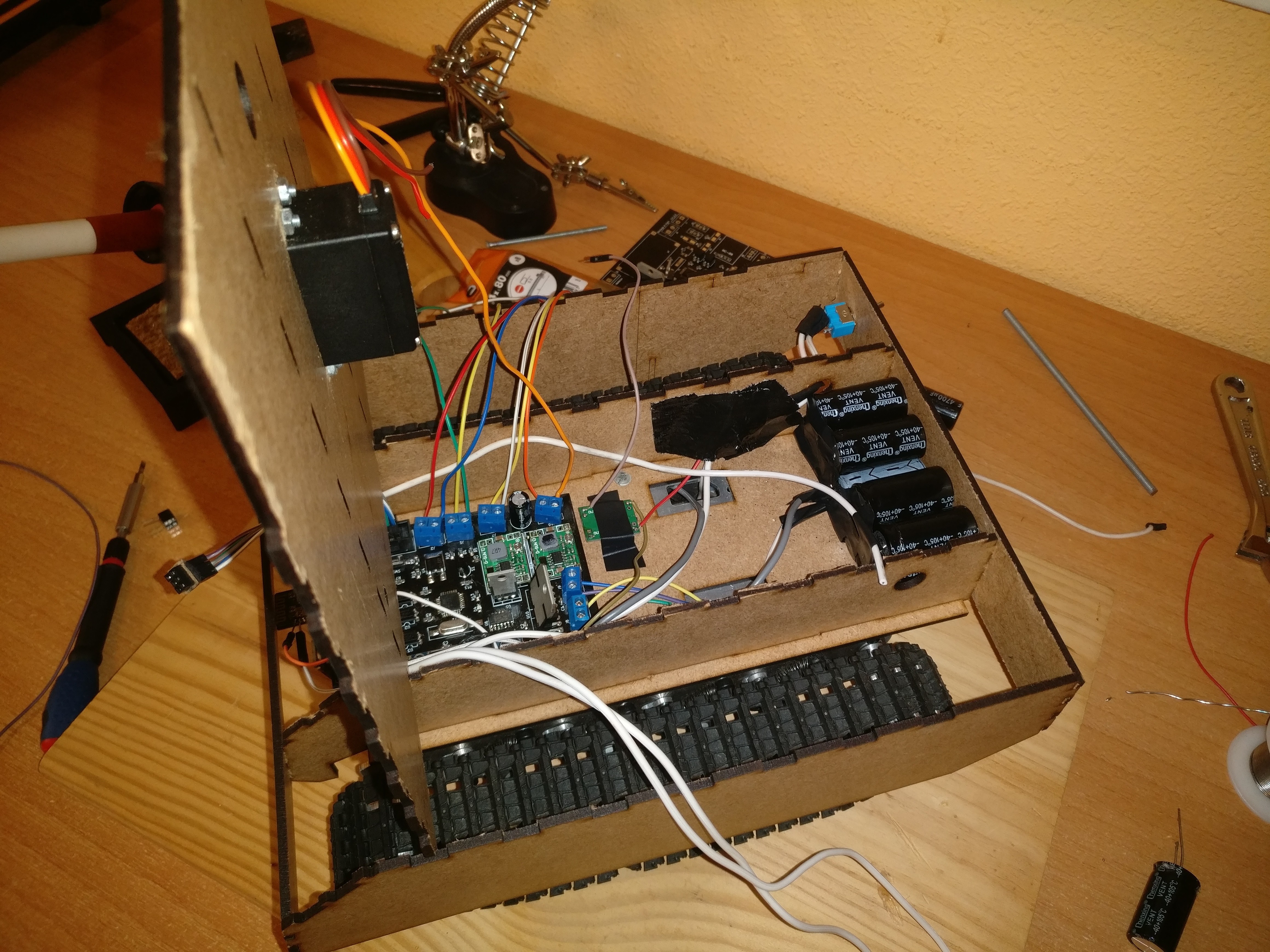
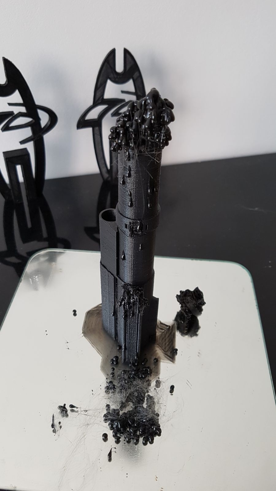
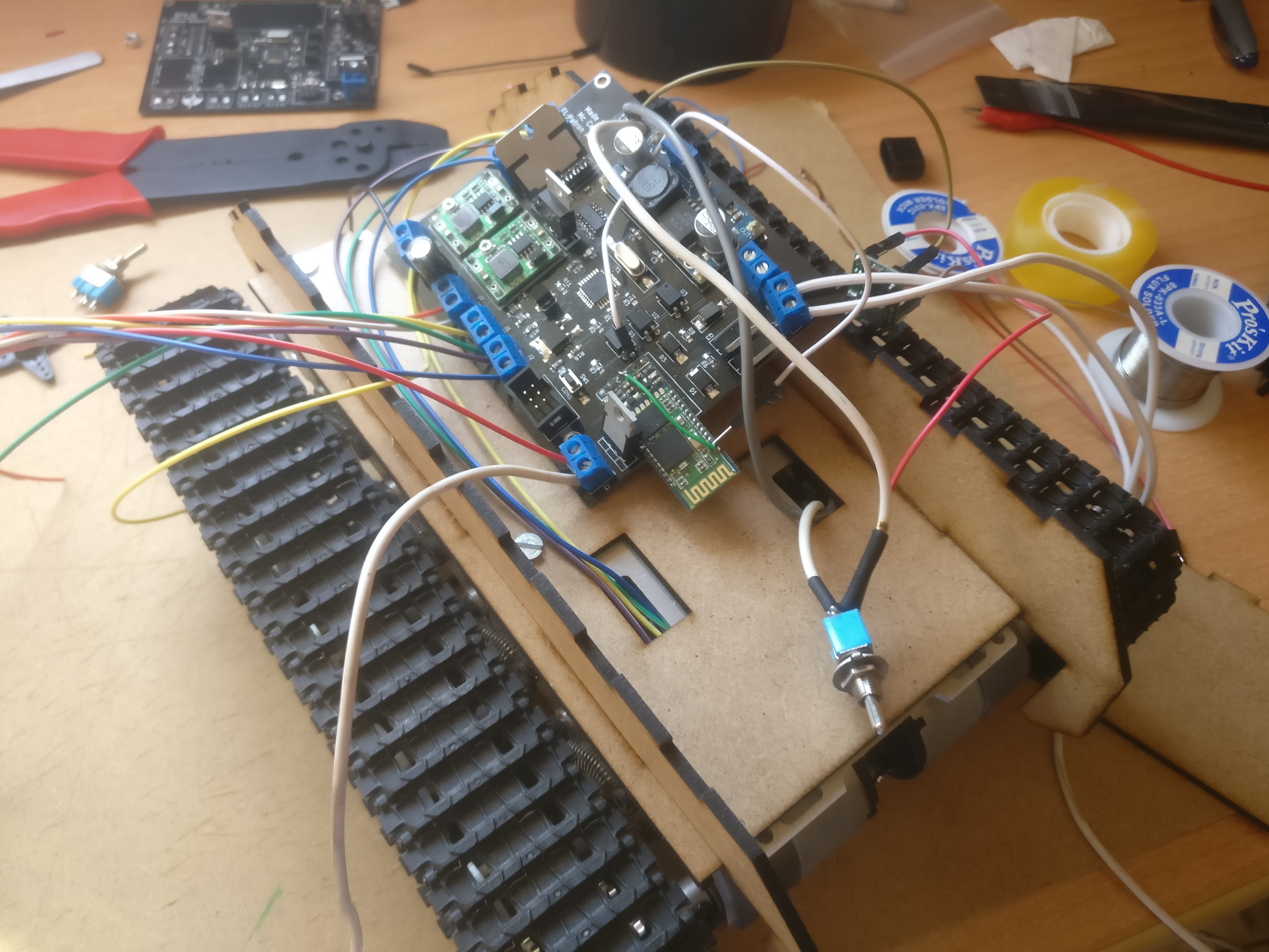
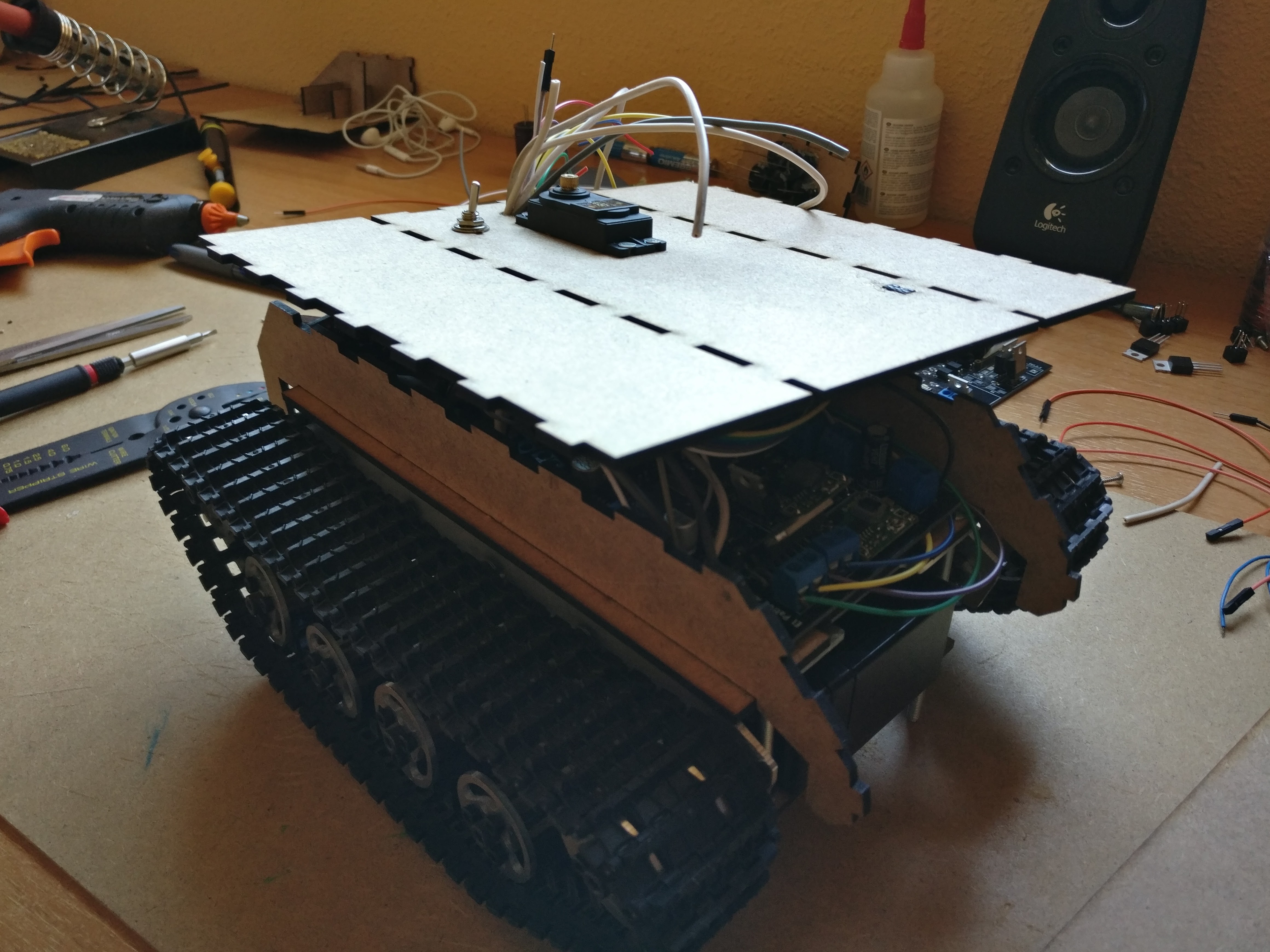
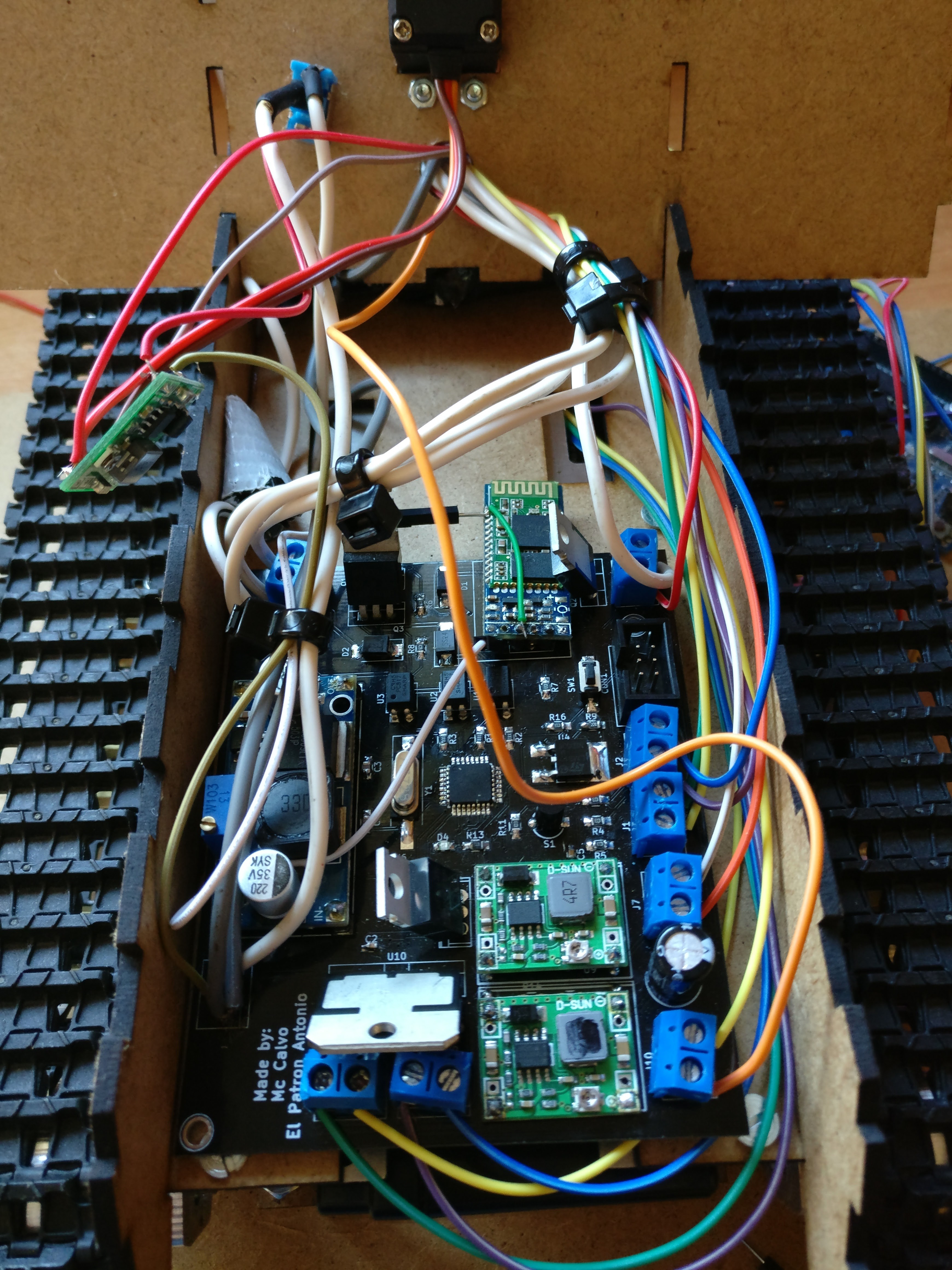
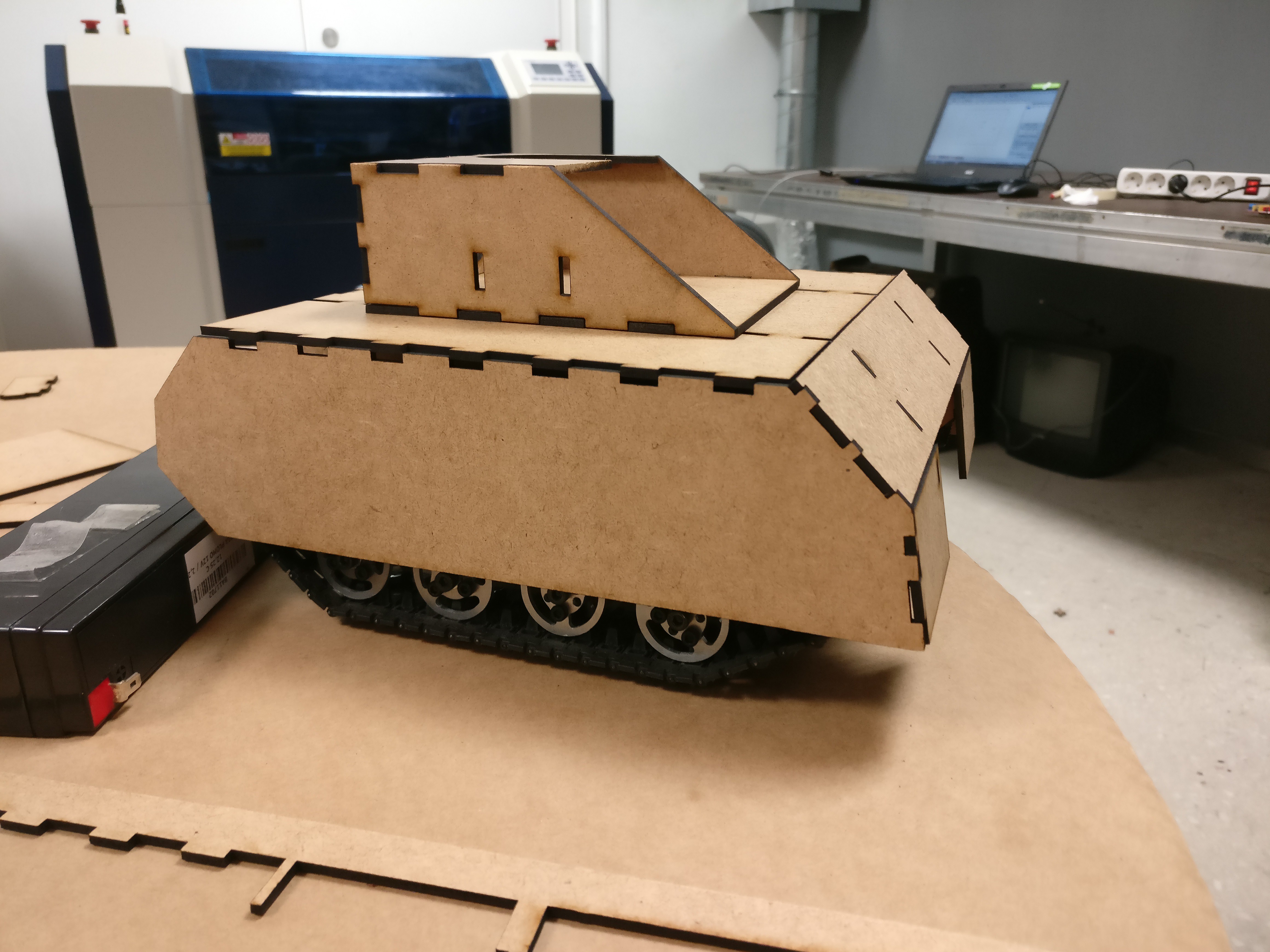
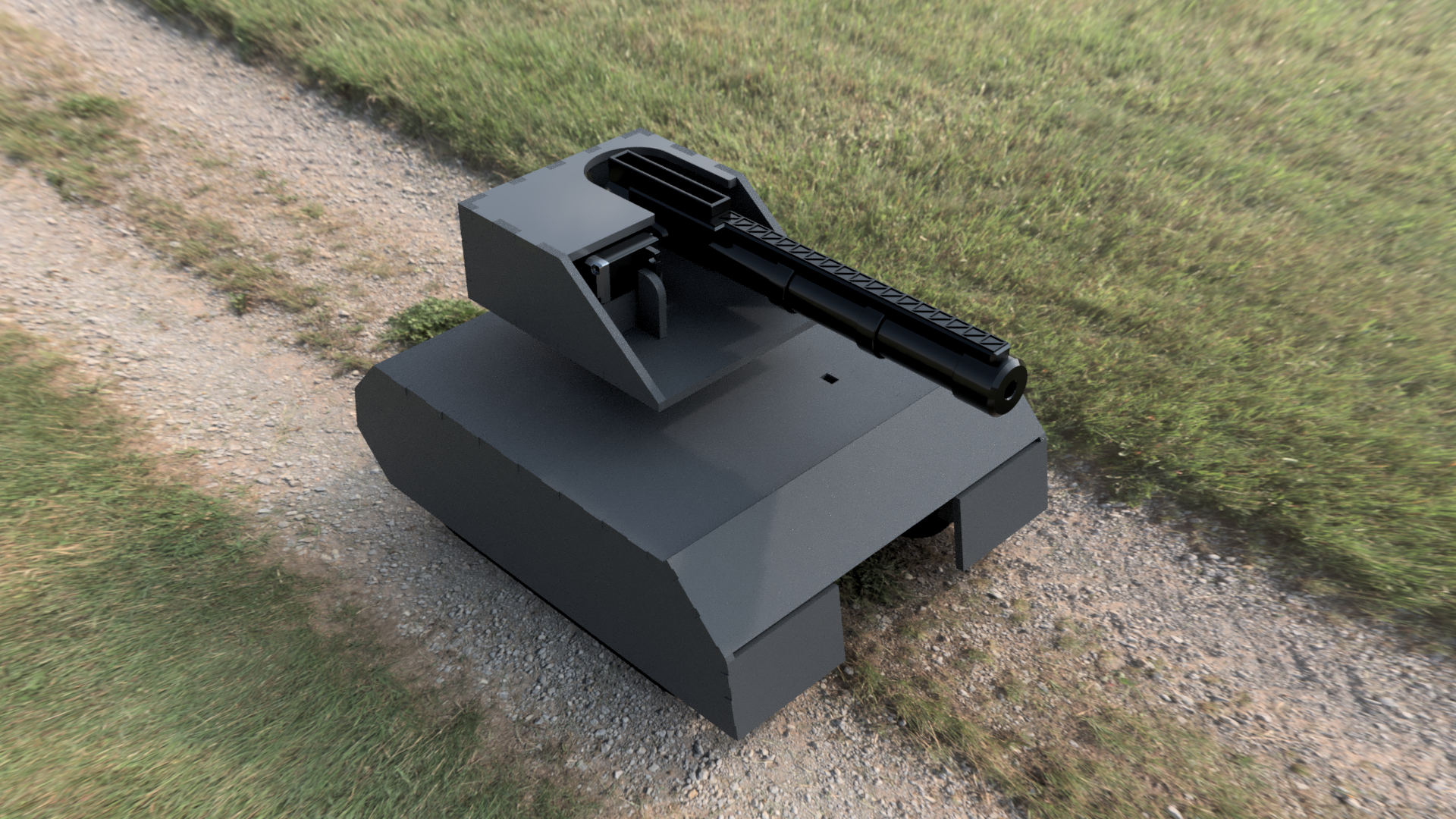
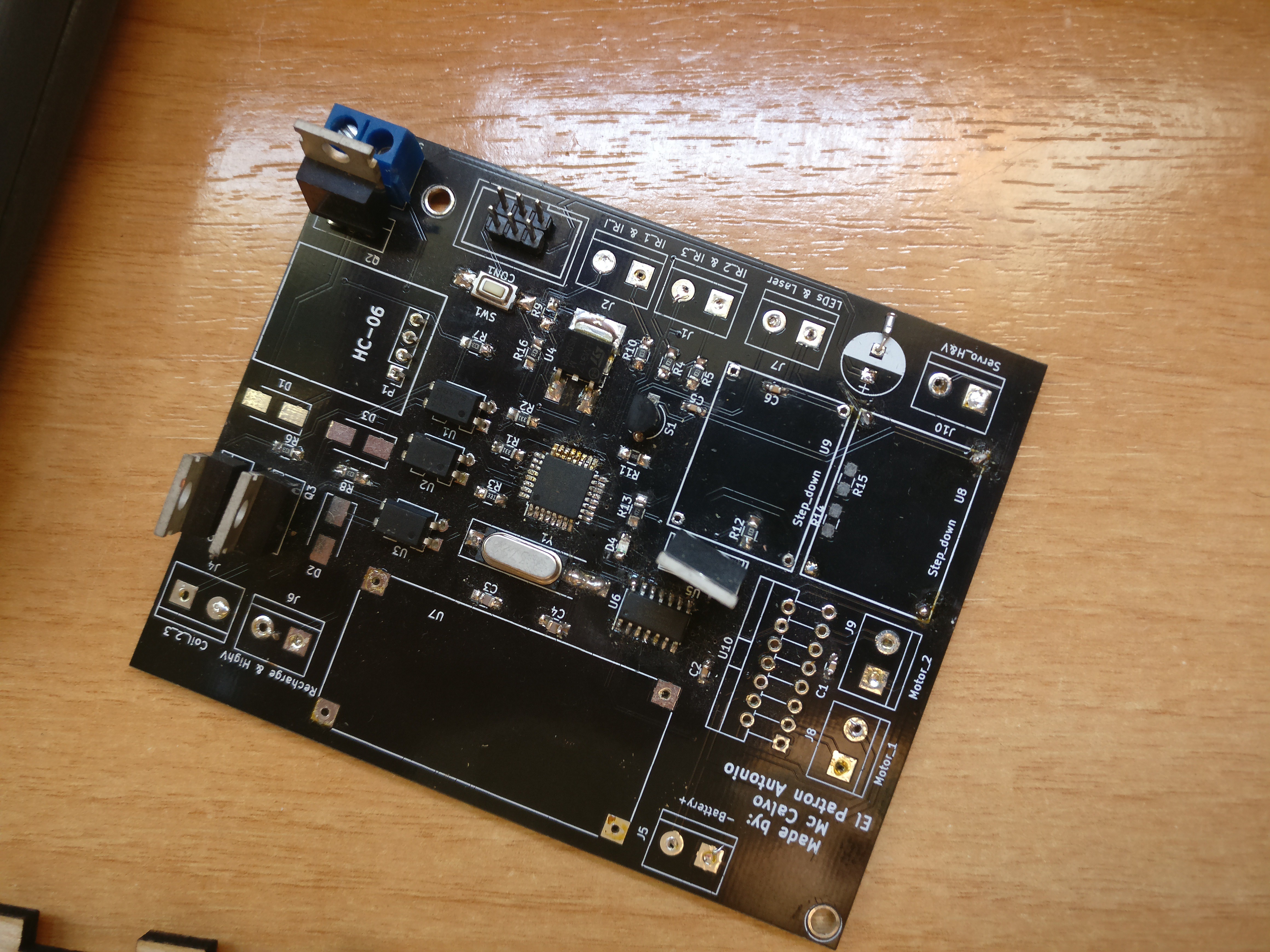
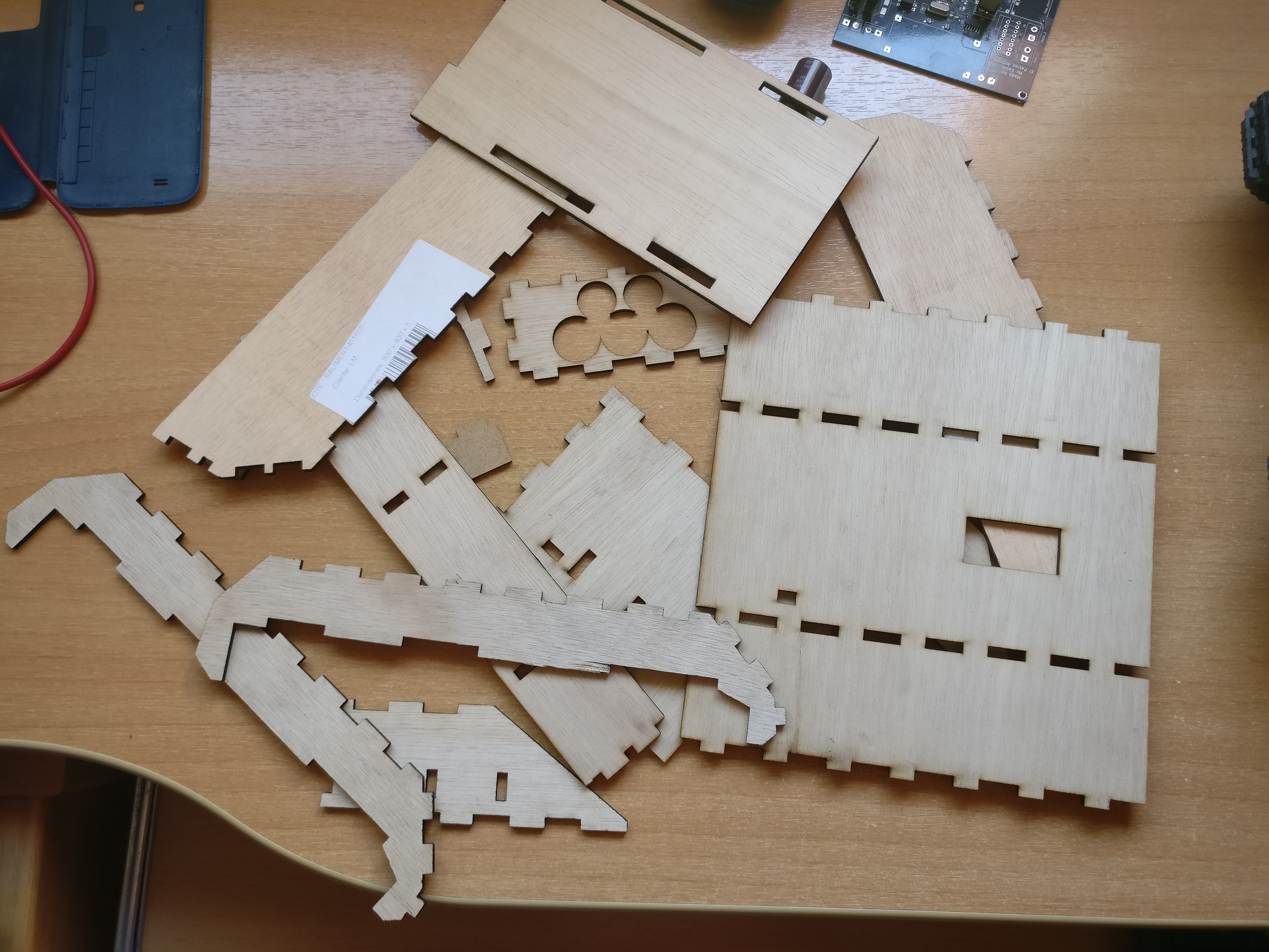
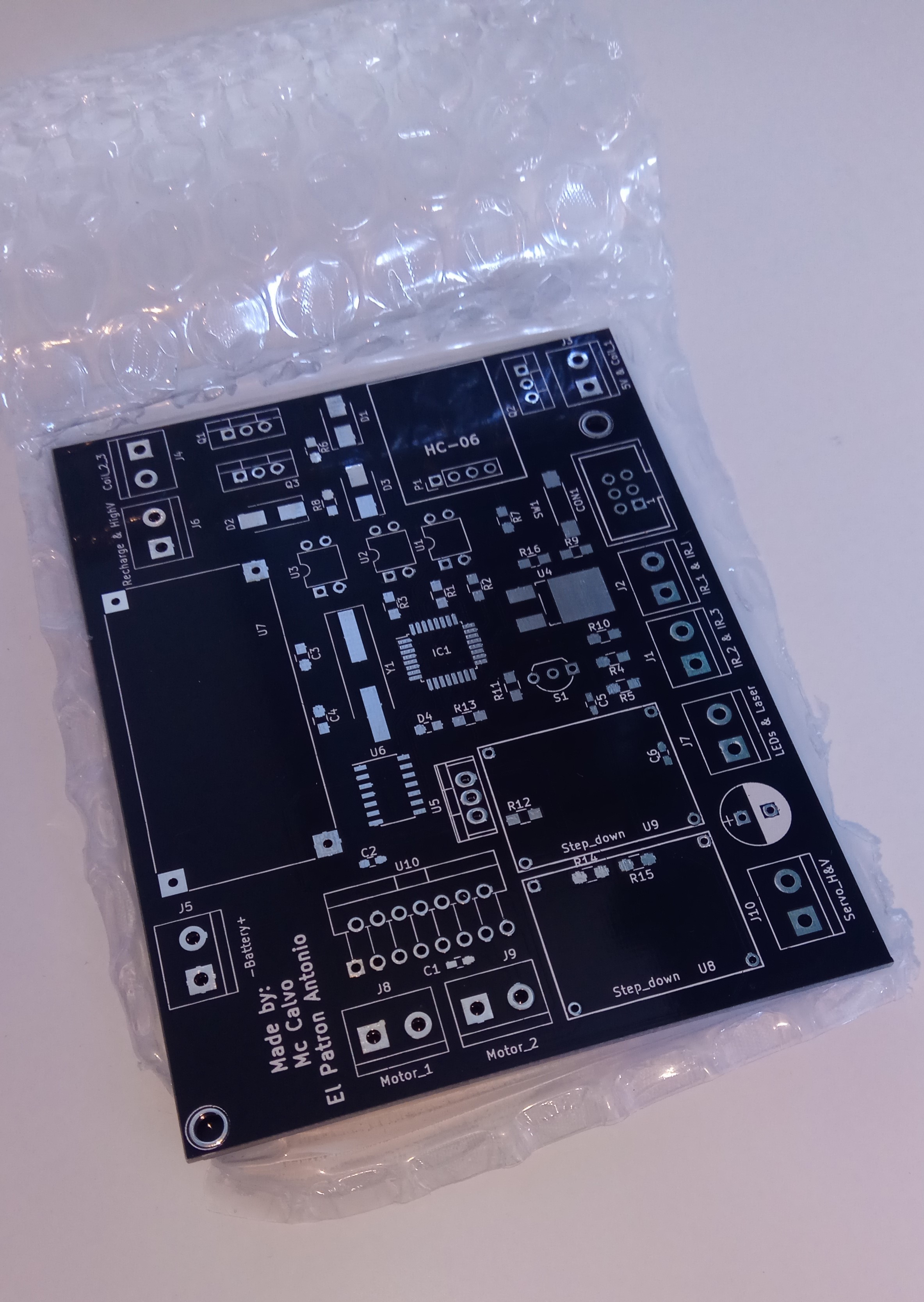
Currently, the tank's movement and turret orientation can be controlled from an Android app that emulates a videogame joystick. The circuit and the tank body is finished, but we still have to 3d print the canon.
This is the list of things that we have to do:
- Program the code for the canon
- Add a LED lighting system - almost done
- Design a reloading system for the cannon's shells. - done? (we have to see)


 Inne
Inne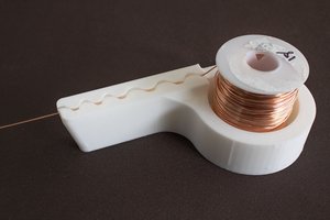
 Roger
Roger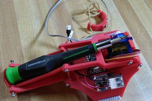
 Tim
Tim
 Mark Howe