 Boian Mitov
Recently I received this cool robot from Kuman donated for the Visuino development :-).
It has Remote WiFi control module, Camera, and 4 servos Manipulator.
The robot has 4 main parts that need to come together:
Assemble and Program Kuman Wi-Fi Robot with Camera and Manipulator
Already have an account? Log in.
To make the experience fit your profile, pick a username and tell us what interests you.
Recently I received this cool robot from Kuman donated for the Visuino development :-).
It has Remote WiFi control module, Camera, and 4 servos Manipulator.
The robot has 4 main parts that need to come together:
While studying the Arduino pins controlling the servos, I received this useful pinmap from another Kuman Robot user, and I am posting it here, as it is quite helpful:
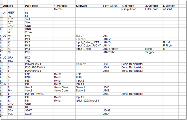
The Infrared pins are added by that user, and are not part of the original robot pin map, but the rest is matching.
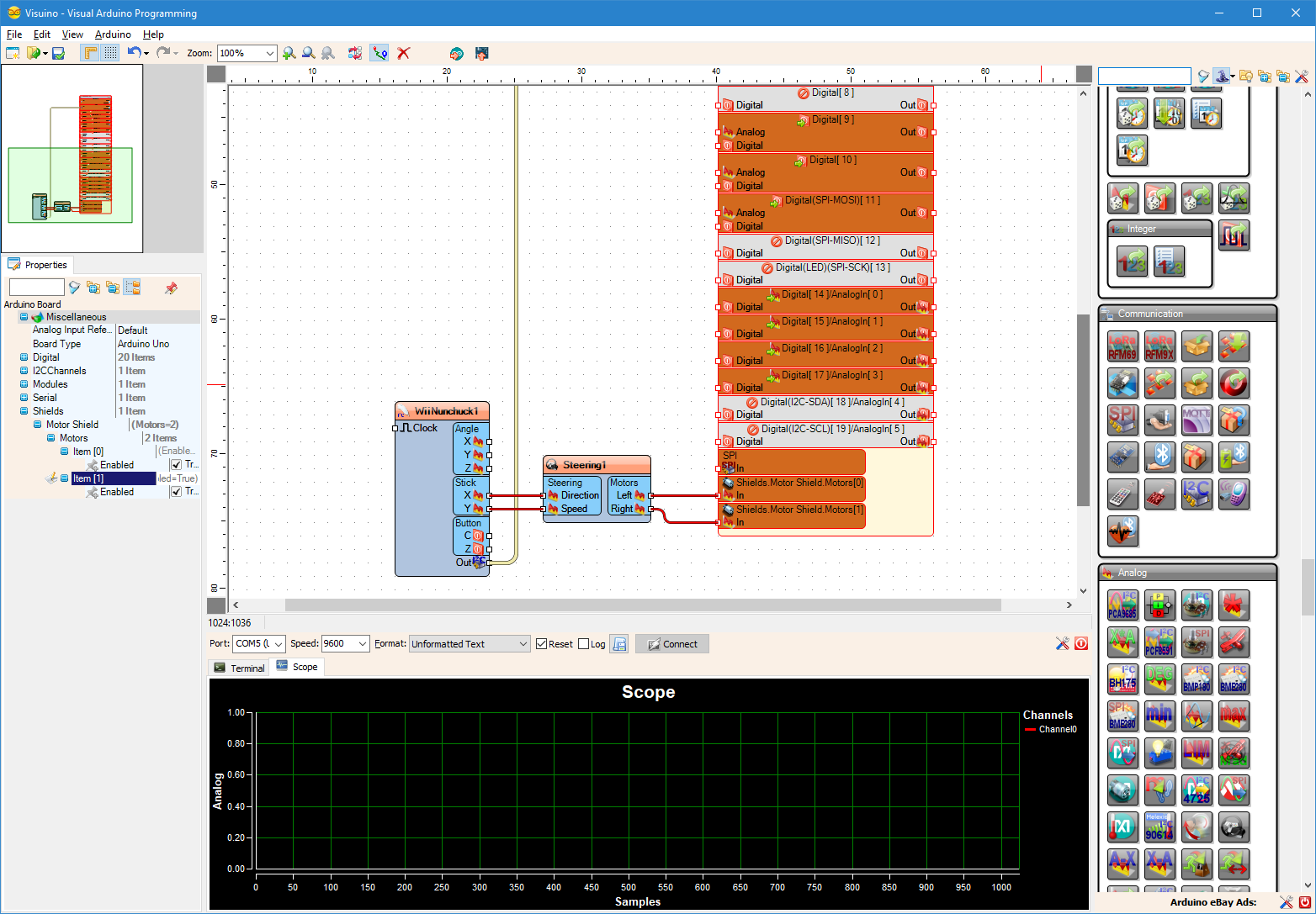
I have already mapped the Robot's shield in Visuino:
Now experimenting with the robot, and working on tutorials.
Unboxing the robot
Assemble the camera mount
Installing the Arduino, Motor control, Servo control, and Wi-Fi Boards
 Victor Joo
 LOFI Robot
 Avi
Avi 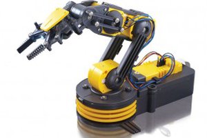
 Campbell Flagg