 circuito.io
Let’s get the electronics out of the way first
Click on this Magic Link to circuito.io and you’ll get a complete list of the electronic parts you need and a wiring guide showing you how to connect all the components. All you need to do is click Generate.
Next is the code section. Follow the instructions on circuito.io: download the code and upload it to your Arduino using Arduino IDE. This is a test code to check your circuit.
Copy and paste the robotic arm code (that is specifically programmed for this project) at the end of the tutorial into the firmware.ino tab (the main tab) of your code.
And now to start working on the robotic arm!
Would my wood be good?
Sure. You can use all types of wood. Check what you have around you but make sure that it’s sturdy yet flexible. As you can see in our project, we chose to use wood scraps that are about 1cm thick. In some places where we needed more robustness, we put two pieces together.
The glue
There are many ways to stick things together: you can use glue, nails, screws and even zip-ties god forbid! For this project, we decided to use a cool technique that we came across - heat shrinks made out of plastic bottles! It’s an awesome technique that you can do with plastic bottles you have at home. Play around and test these a little, you’ll be surprised how strong they are.
Construction
So we have our basic building materials, and now we need to think how this whole thing is going to be structured. Now is also the time to take into consideration which servo motors you’re going to use and where to place them. The arm moves in three axes, so we’ll definitely need 3 servos. Here’s a good article that explains how to choose a servo motor for your project. We’re using Sparkfun Servo - generic metal gear that is available to use on circuito.io.
Bottom-up or top-down?
When figuring out the structure, we took a bottom-up approach Starting with a solid base so that the arm doesn’t tip over. At the same time we also needed to understand what would be the best way to bind and tie the pieces of wood together so that the base is solid. In the picture below you can see the way we used the heat-shrinks and a potato (!) and base as the weight.
Location is everything
Placing the second servo was more tricky and we feel that this area still needs some attention. We realized, after building the prototype, that we hadn’t given enough thought to balancing the upper arm. Therefore, the servo motor draws a lot of current - something that can be overcome by using counterweight on the opposite side of the arm.
Get a grip
There are different types of grippers we considered, and we weren’t really sure what we're going to do here. Eventually, we decided to make one side of the gripper static so that it will have a strong grip. As you can see in the image below, for the moving part we made a joint, that is controlled by the servo and added a spring for closing and opening.
Tying it up
We used a standard piece of string that runs inside a plastic tube to connect between the servo motor and the gripper, the same as in bicycle brakes.
That’s basically it!
Now you can start moving the robotic arm around using the Joystick, make tweaks and changes to the code and mechanics, and maybe you’ll even find a way to improve our design. We’d love to hear your comments and experiences with the project.
We’ll finish with the words of Adam Savage in his famous “10 Commandments for Makers”:
Don't wait. You can start now with what's in front of you. As Goethe [may or may not have] said, "Begin it!"

 Nick Rehm
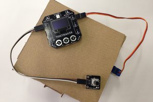
 TokyLabs