 Nelson Phillips
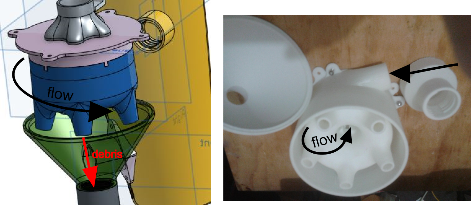
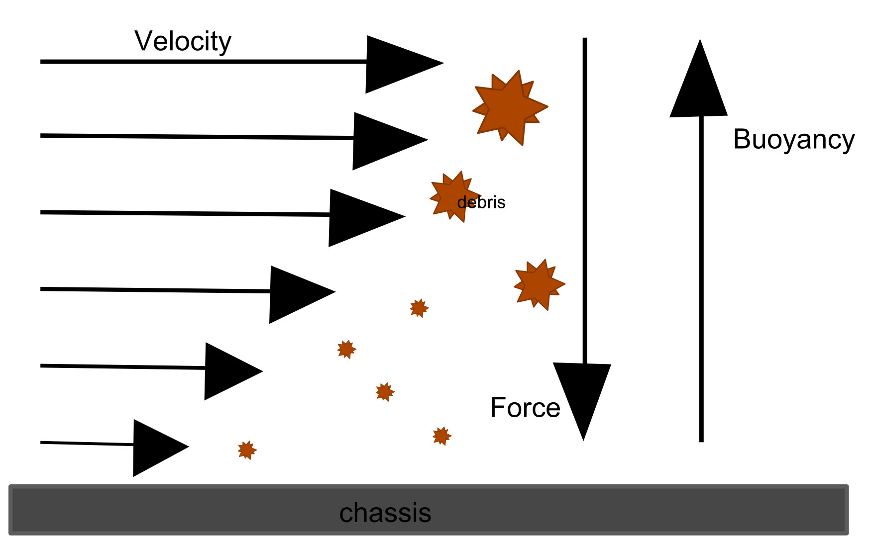
Cyclonic dust extraction methods aren't new and are common in industrial settings. The principle is that a vortex is created with rotating air. In the middle of that rotation is low pressure and the more energy that the vortex has the greater the difference in pressure, eg lower. So using the low pressure region and the centrifugal of the rotation a complementary mechanism exists for the particulate extraction process. Air at the centre of the rotation has the lowest pressure and only the most buoyant substance can sit there which is only the cleanest of air. Extracting this air with a vacuum pump is essentially do the most natural thing for a cleaning process.
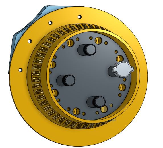
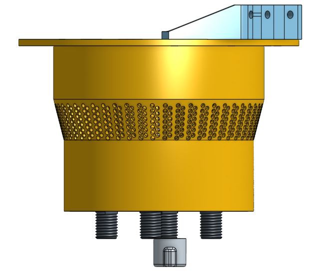
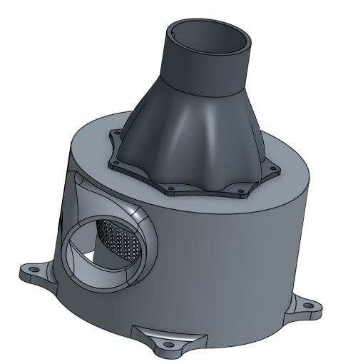
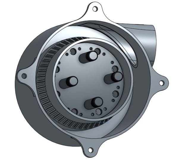
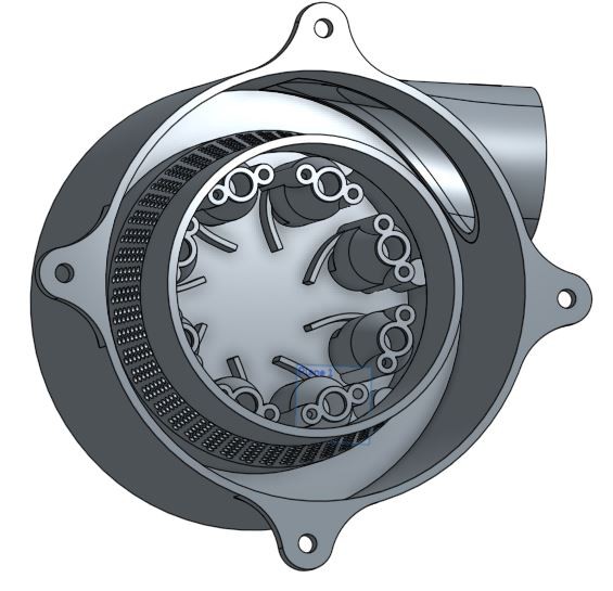
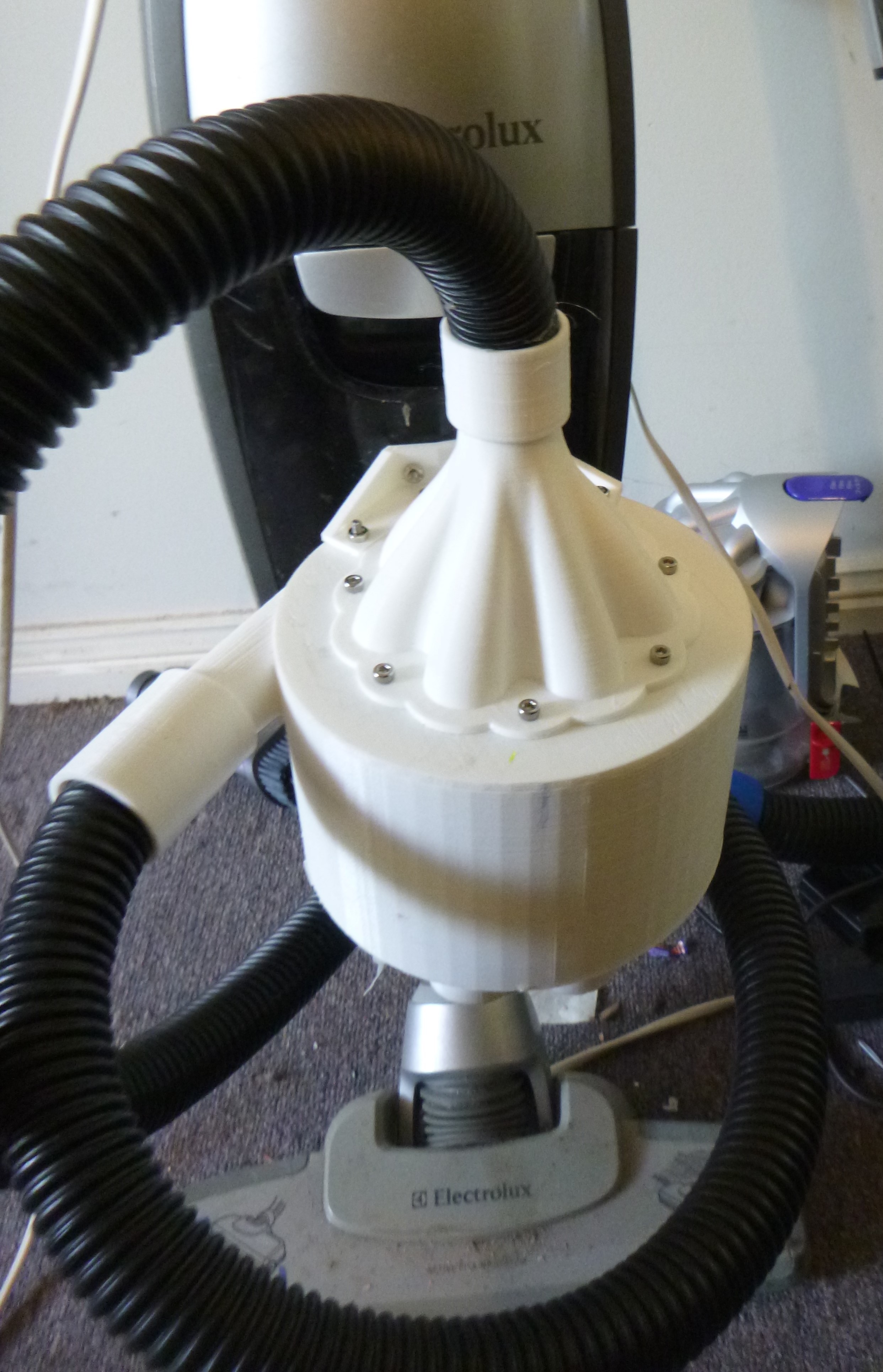
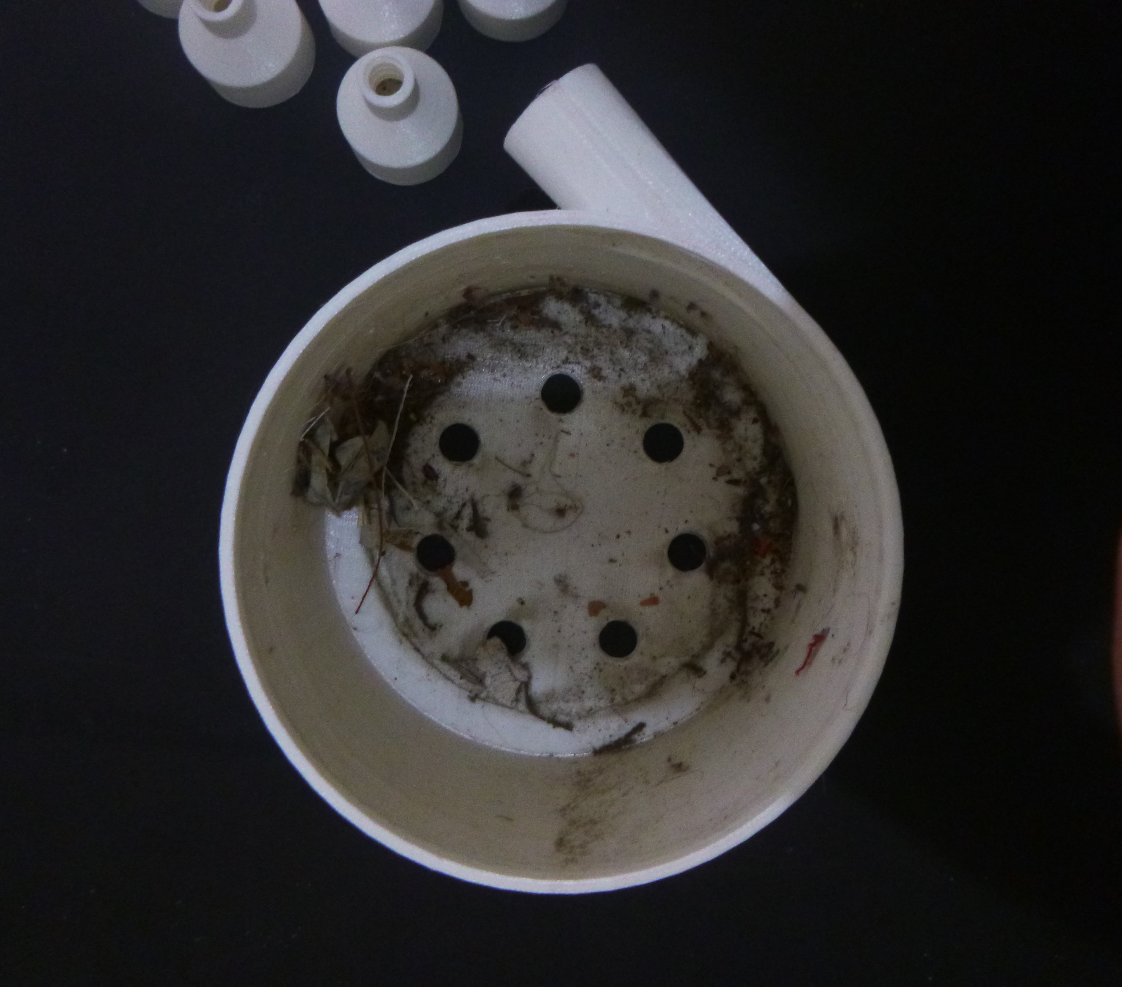
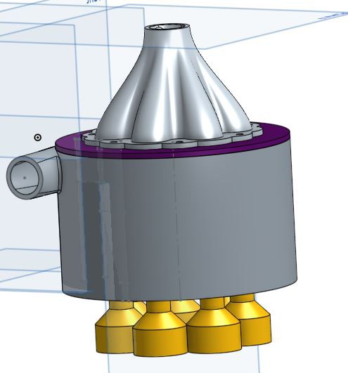
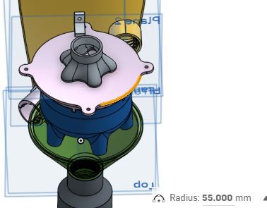
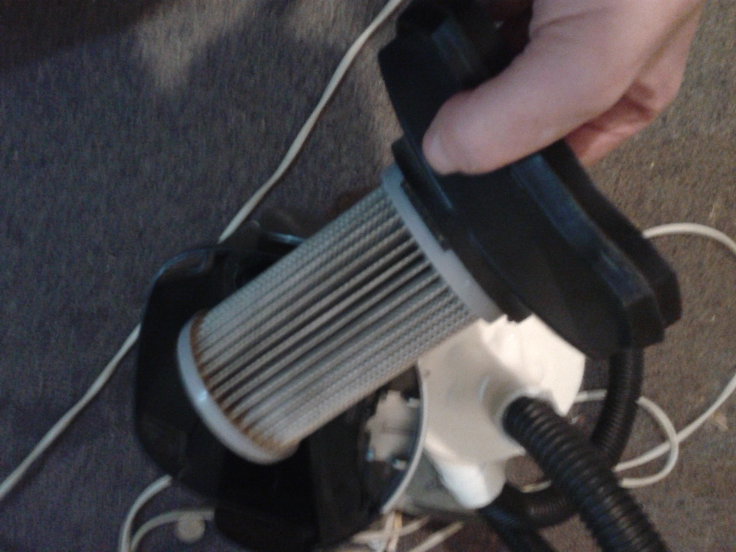
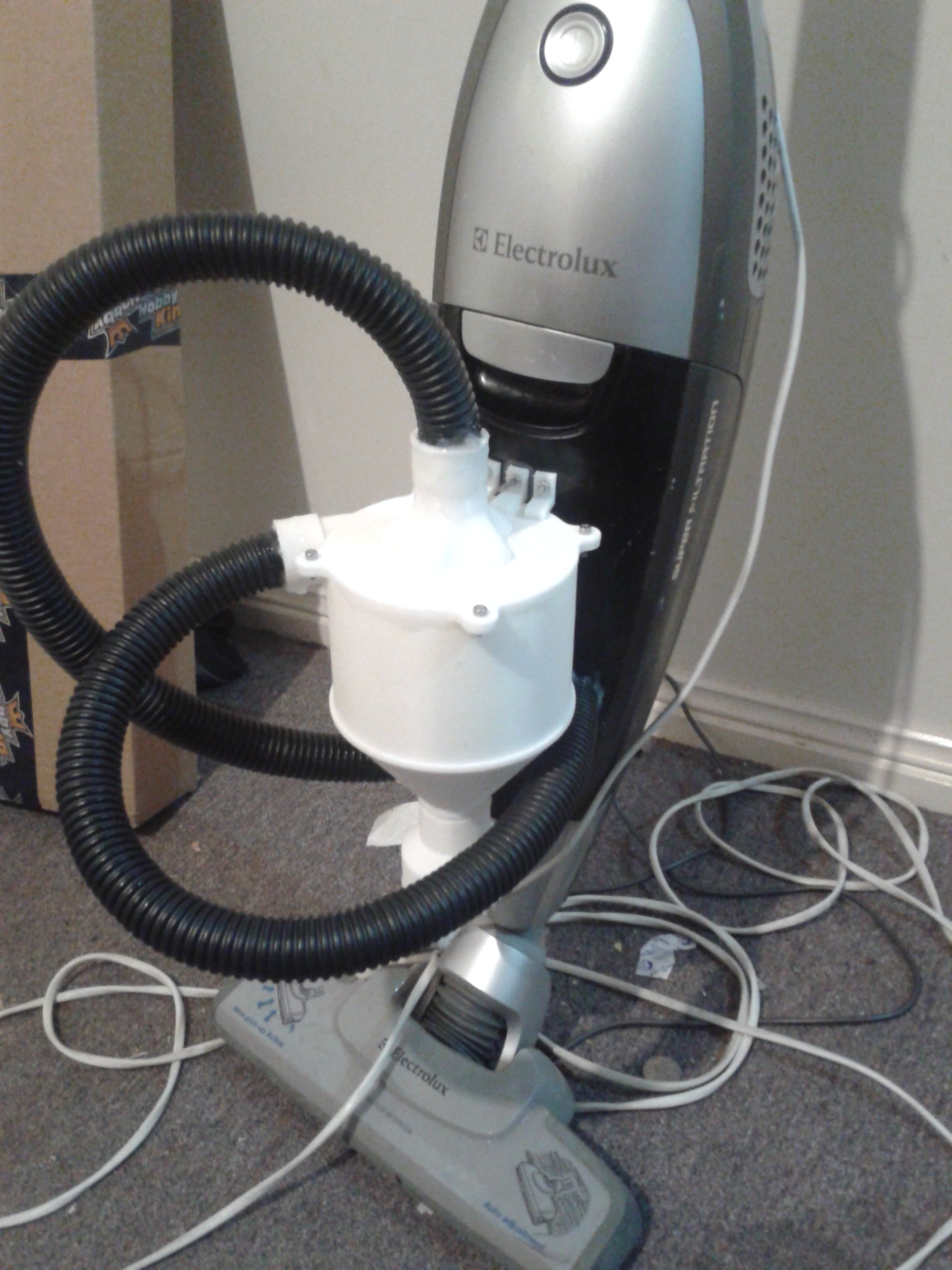
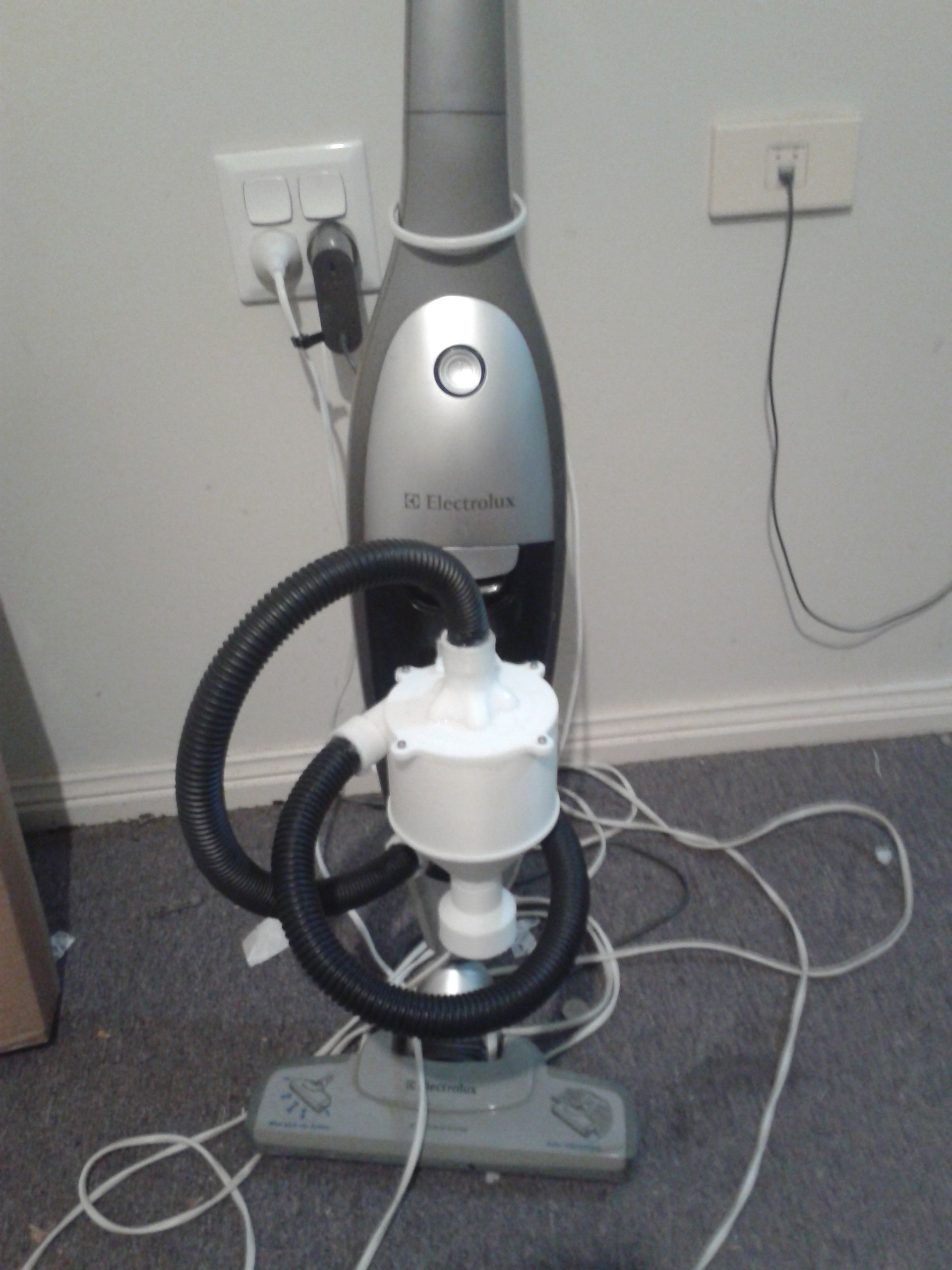
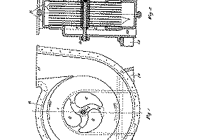
Typically industrial dust extractors use a single vortex that removes the large particulates that cause dust. The commercial domestic vacuums require more finer particulate to be removed and use very small vortices to do this. Without going to this extreme this project created a 8 vortex system, in the latest iteration, with and external vortex that induces the rotational air structure.


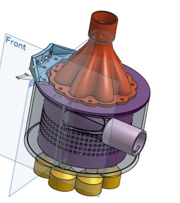
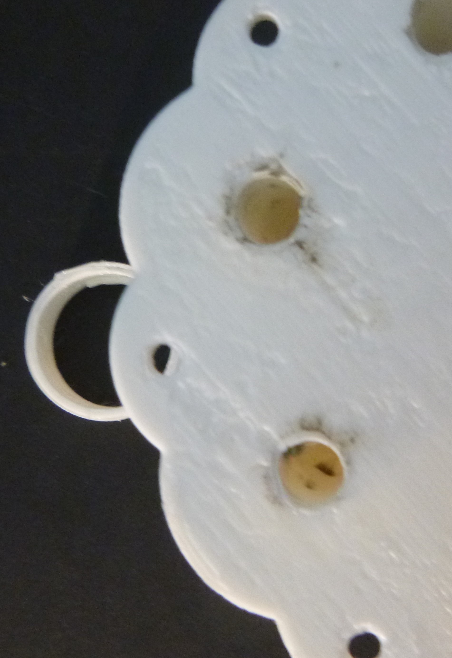
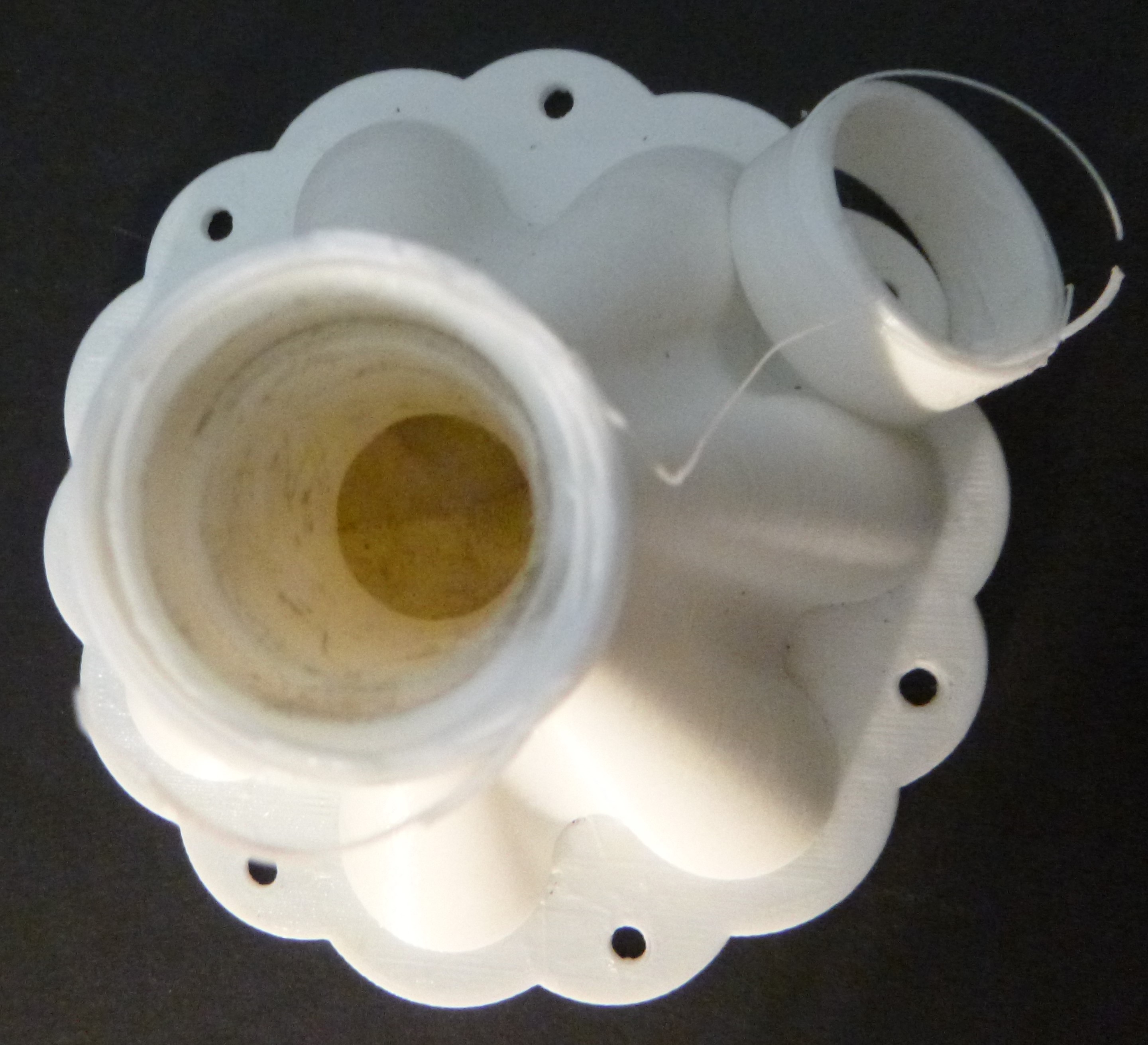
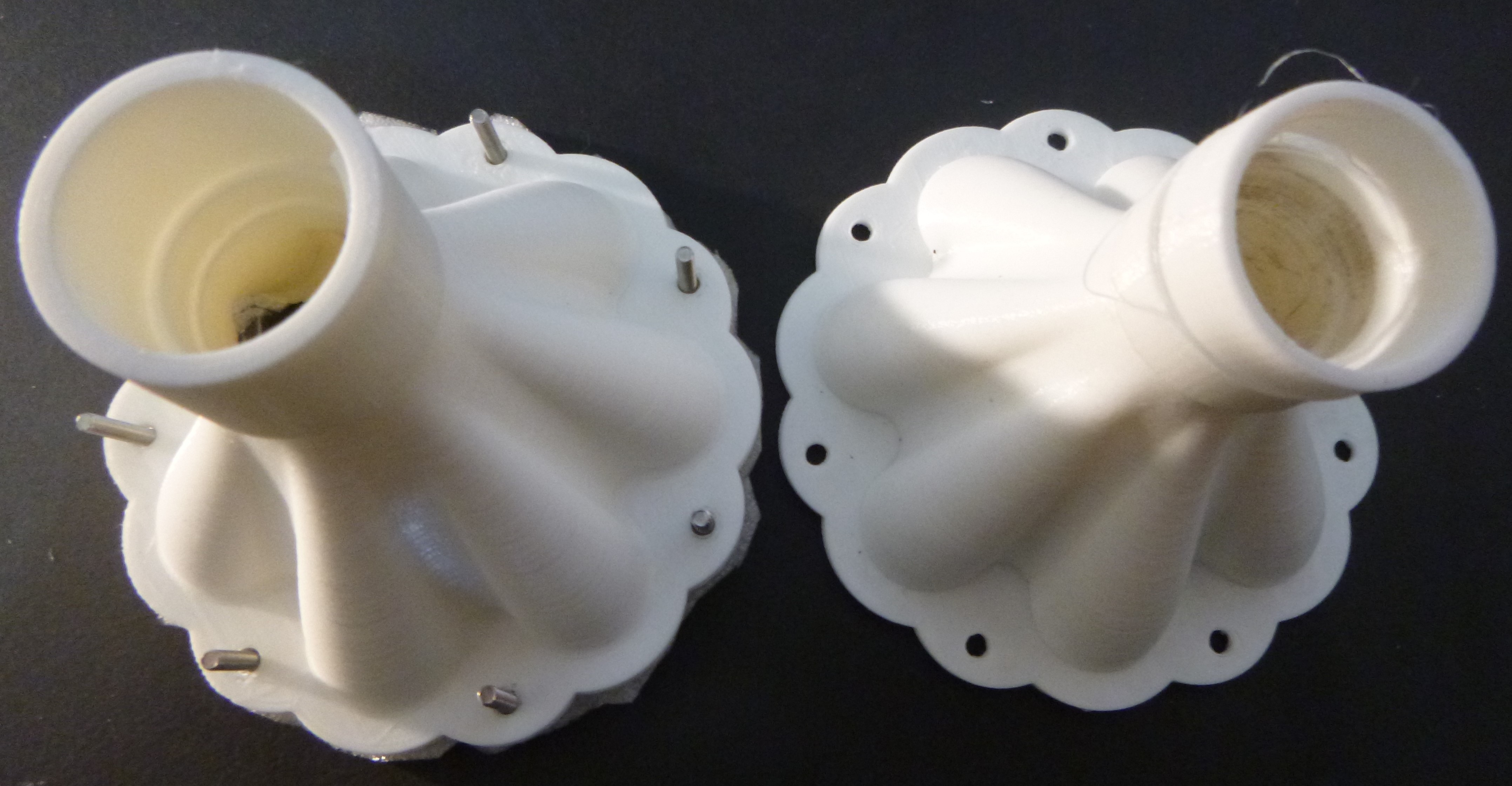
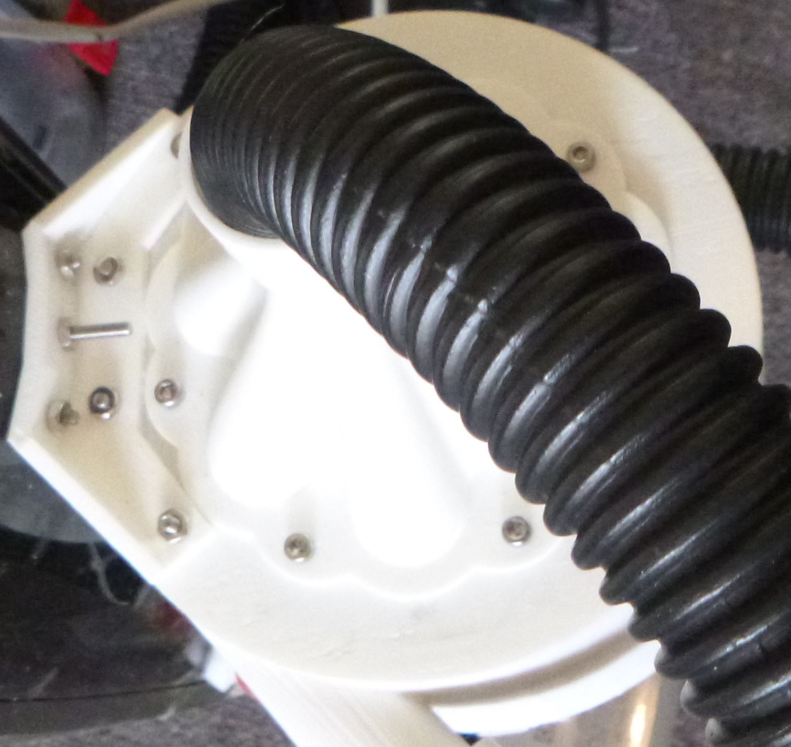
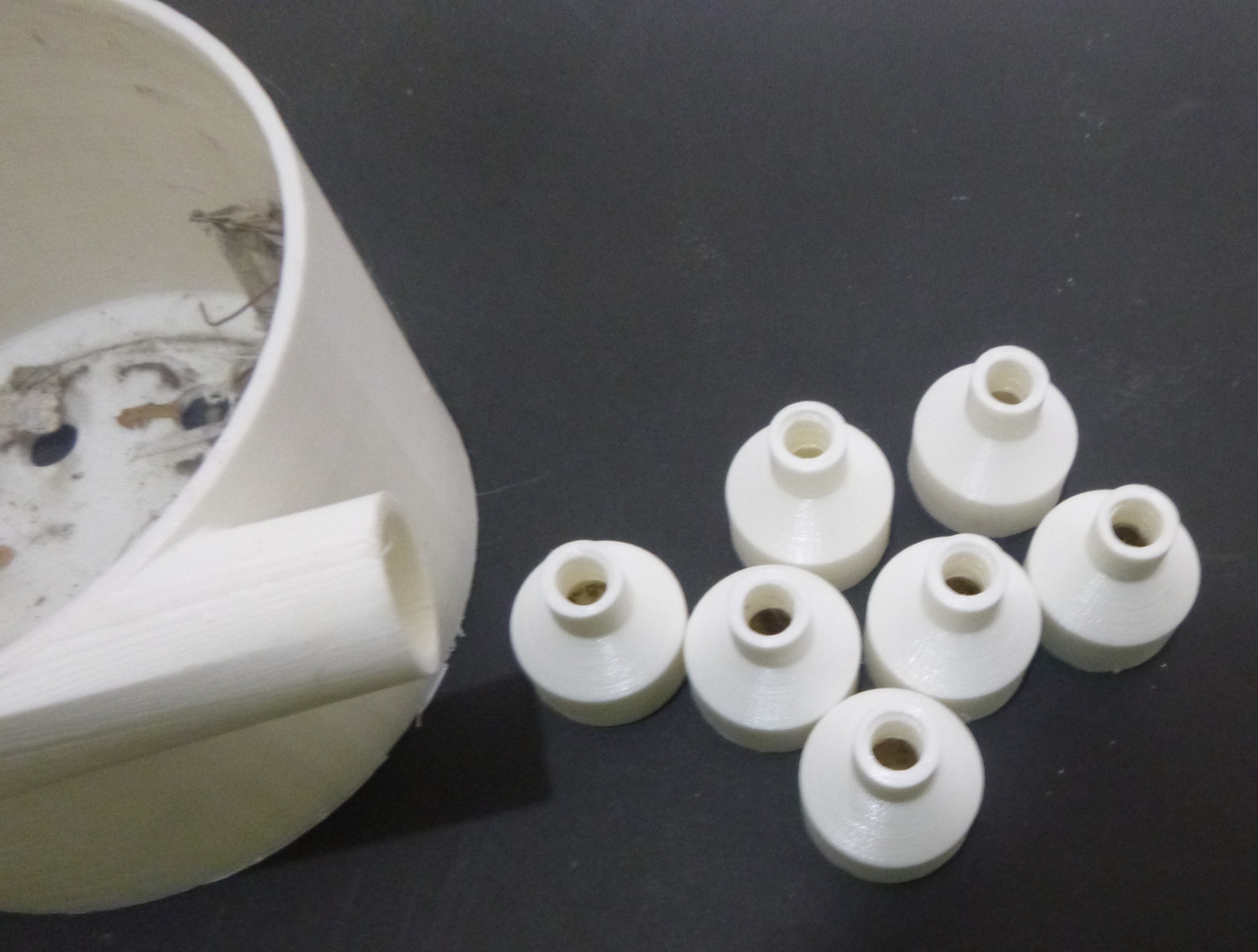
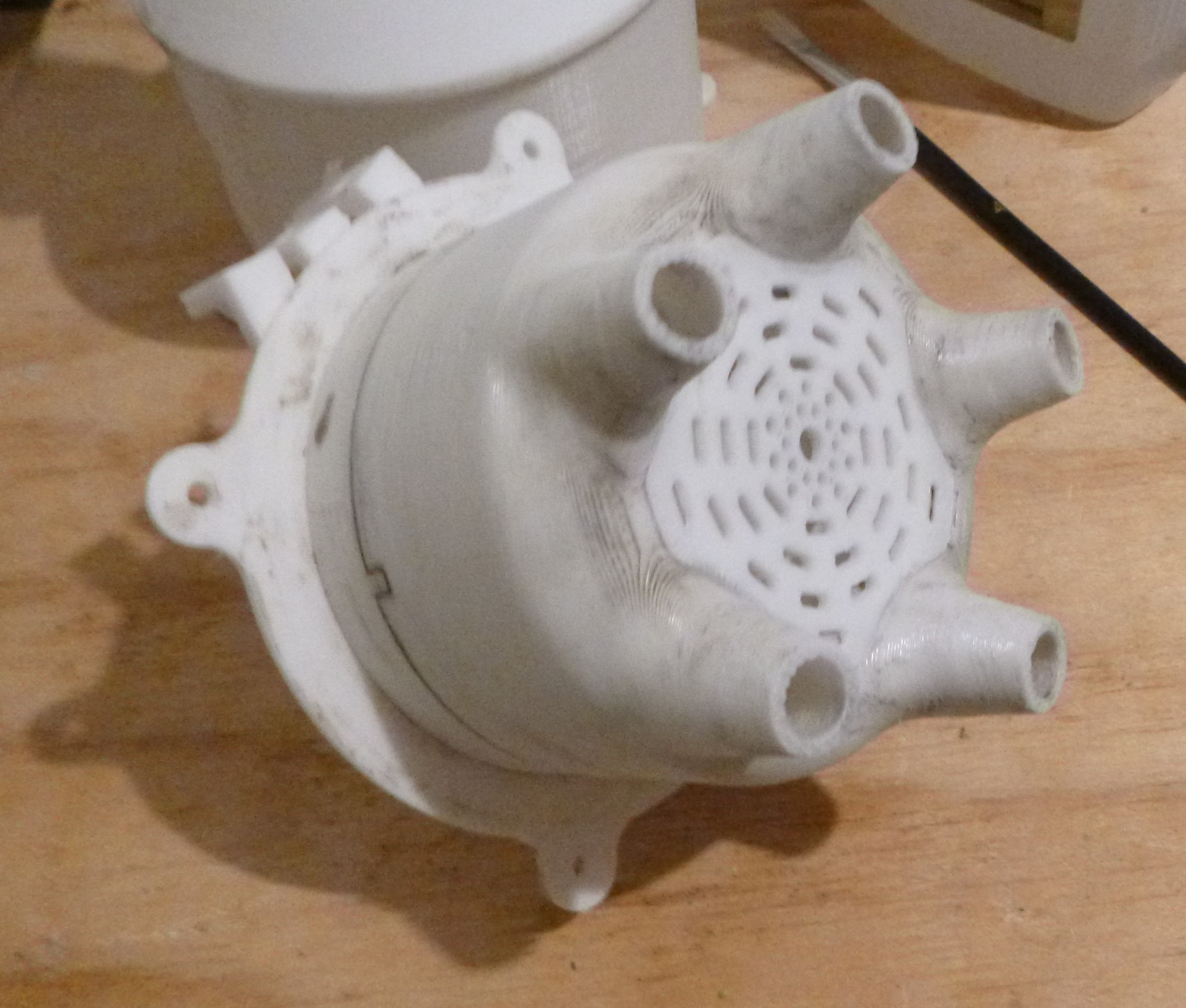
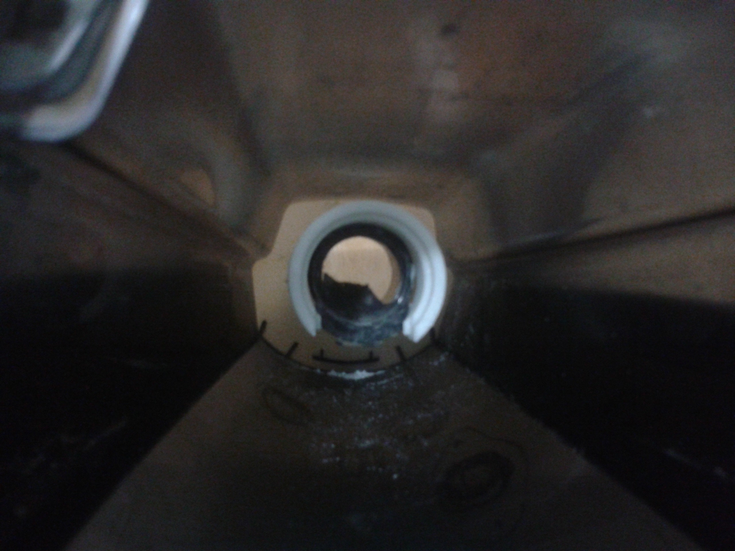
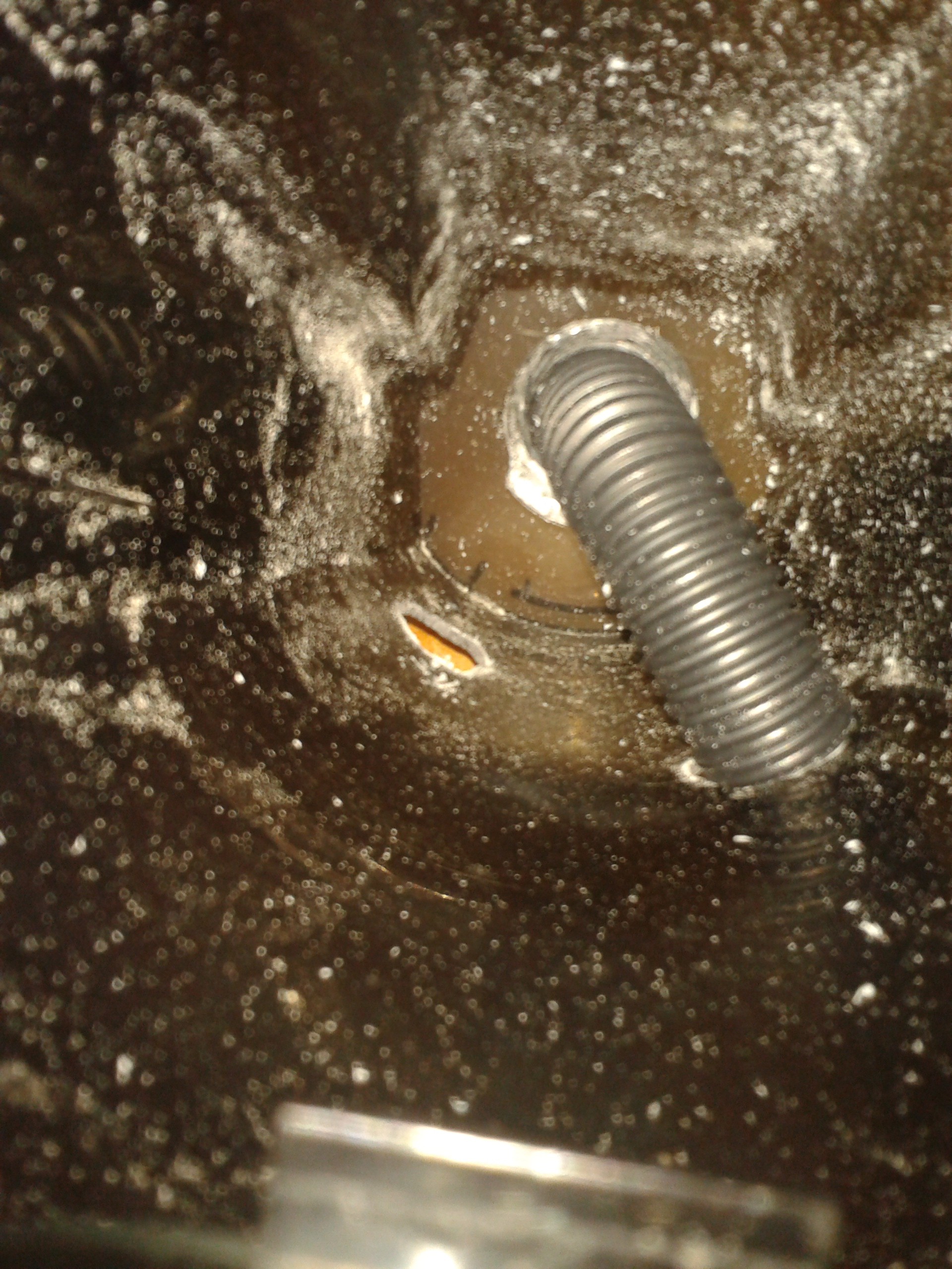
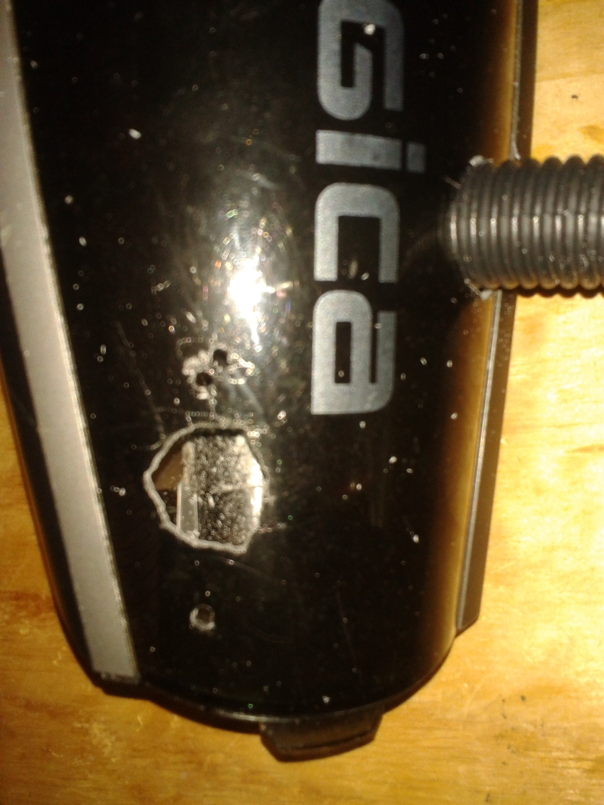
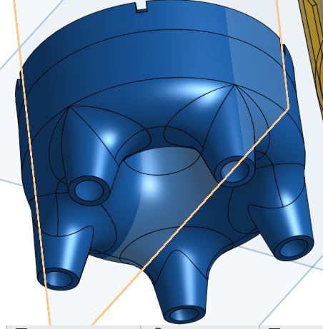
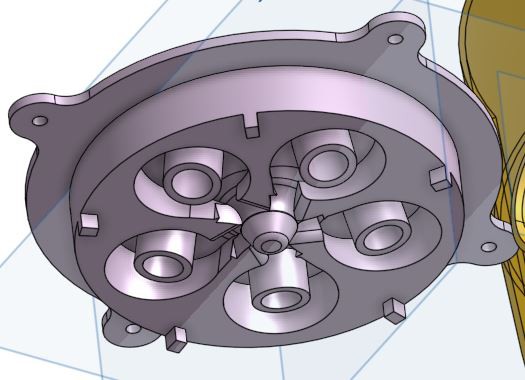
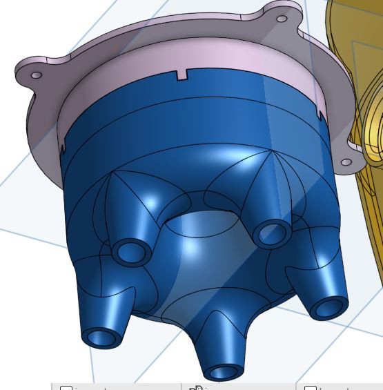
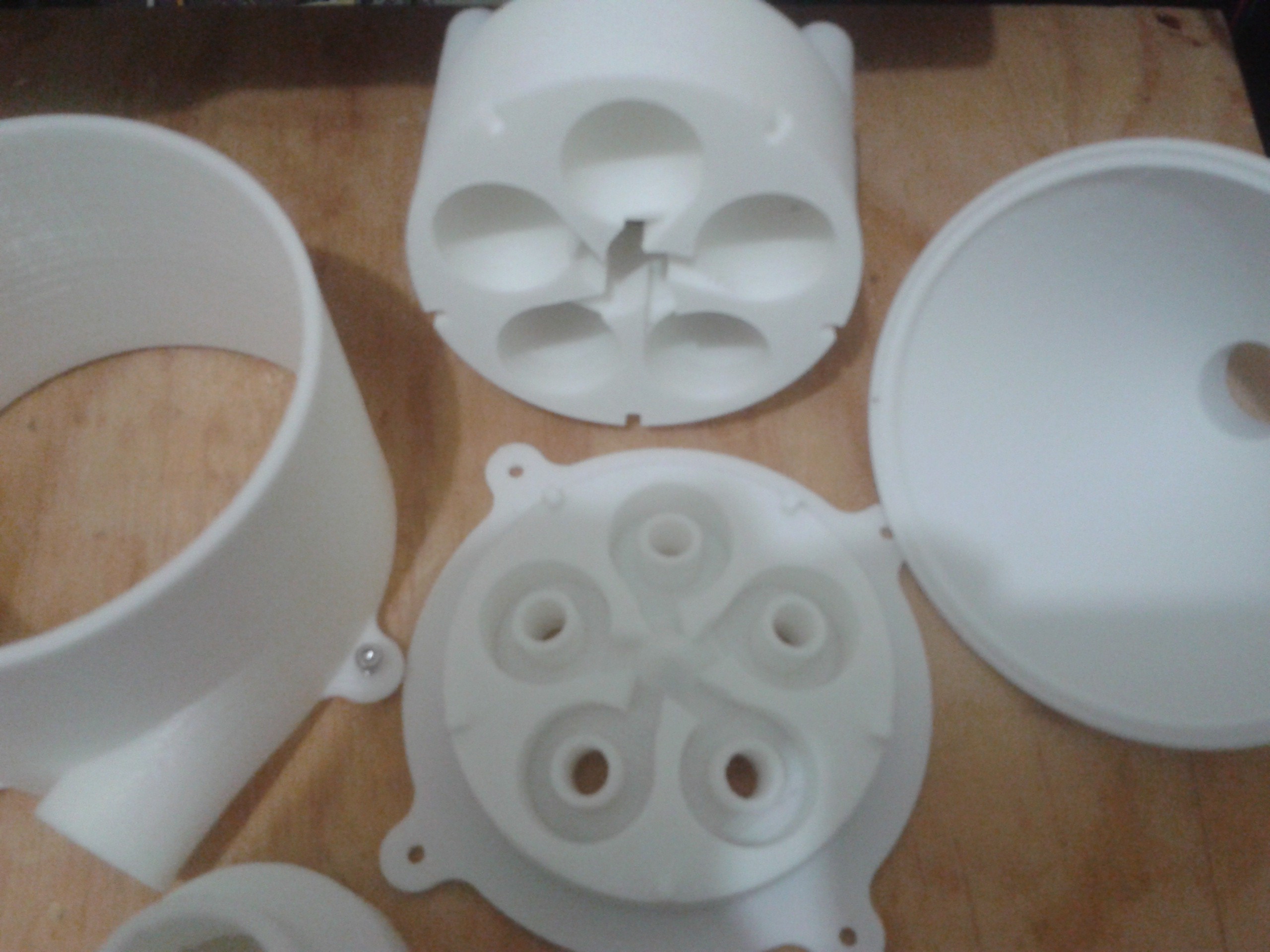
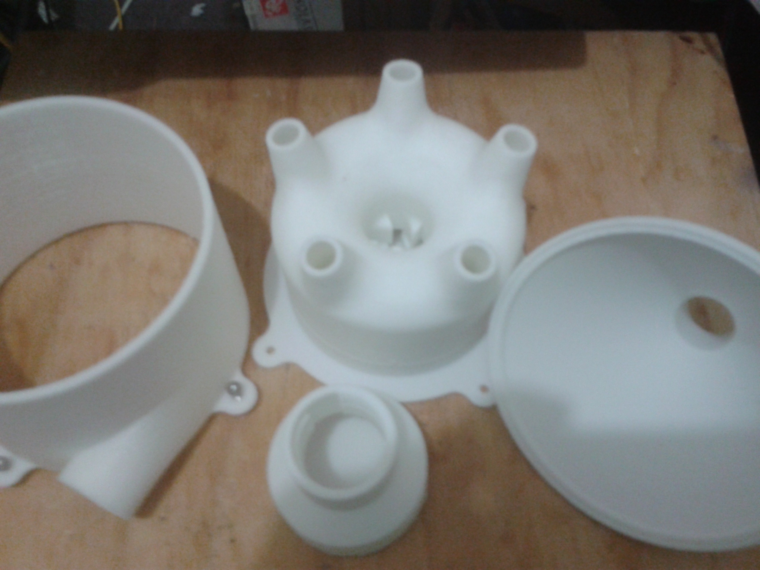
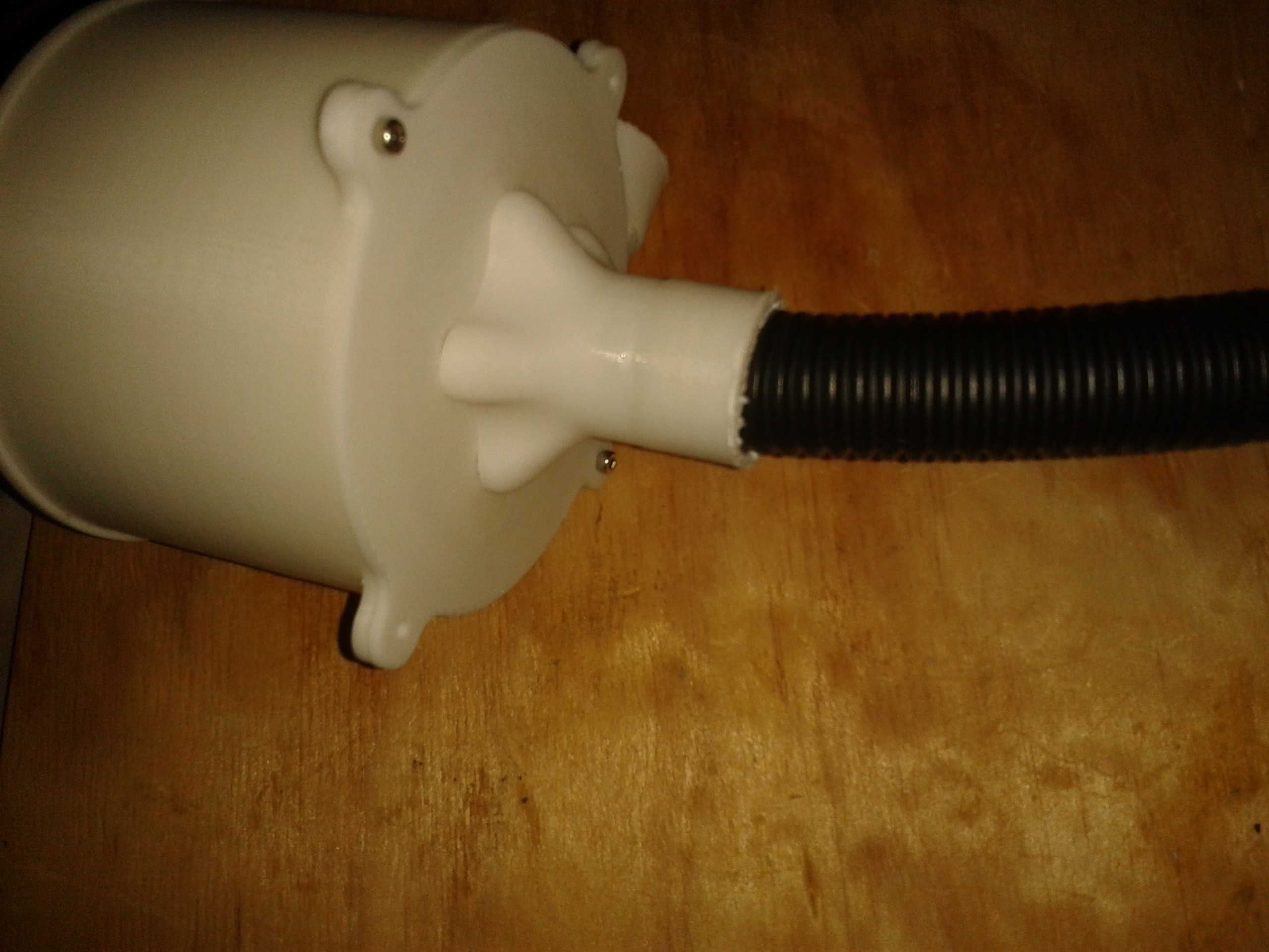
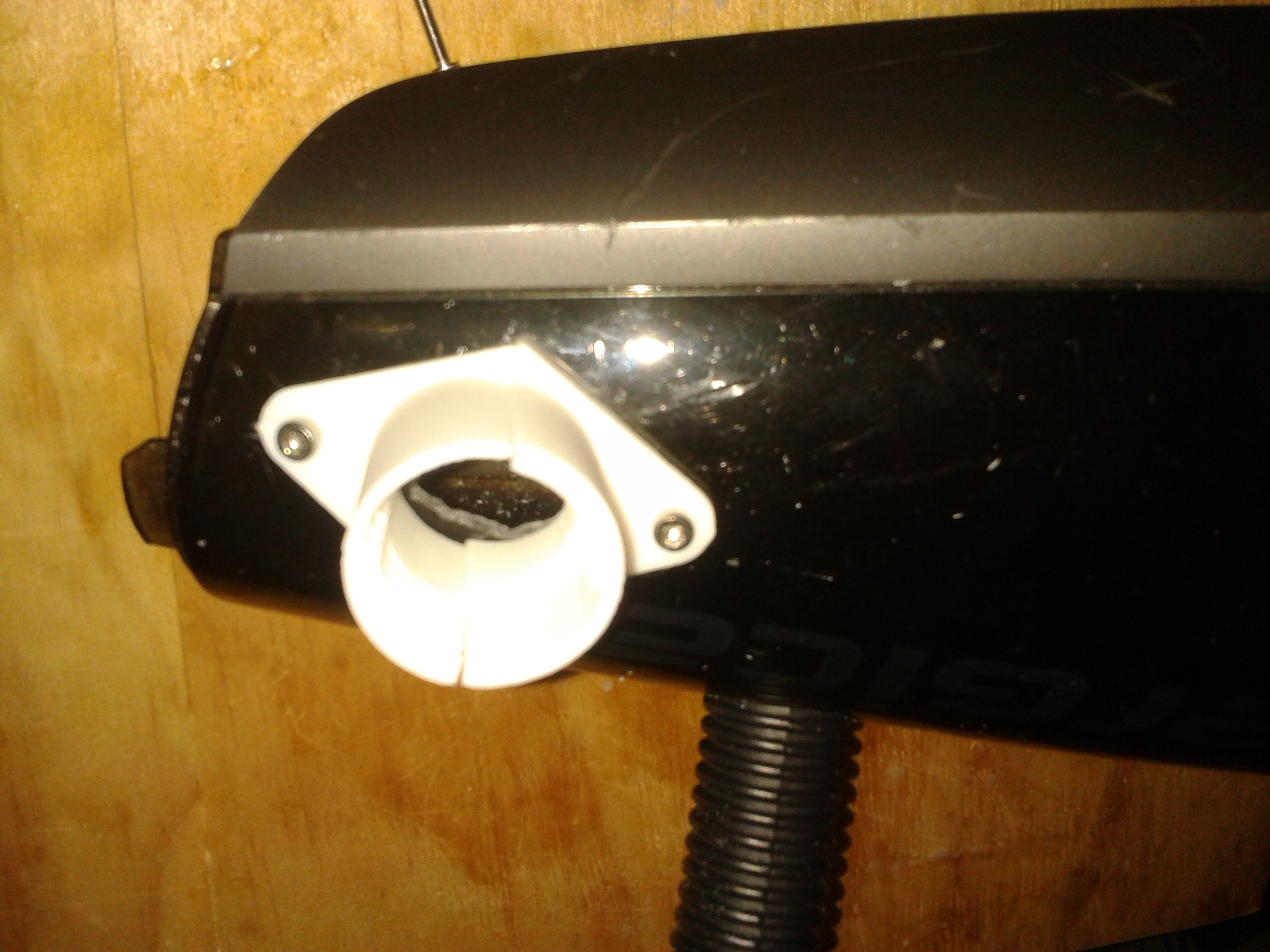
These image shows the versions of vortex generator that the inlet air structure rotates about. Large particulates are removed here as the air accelerates over the curved surface and into the inner 7 or 8 vortex generator. The slow moving 'high' pressure air that contains the particulates from the small vortices exits below the accelerated feed air and should mix with the large material and fall to the bottom.


 David Troetschel
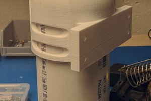
 Andy
Andy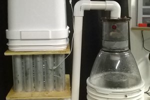
Nice iterations, thanks for sharing. Please allow me to join