Close
0%
0%

Desktop Arcade Machine : 3D Printed + RetroPie

My attempt to build a desktop arcade machine by 3D printing the cabinet and using Raspberry Pi 3 running RetroPie.

Similar projects worth following
I always wished I had an arcade machine with real arcade joystick + buttons. Now that I have a 3D printer, I thought I should put it to good use and make myself a desktop arcade machine. I used TinkerCAD to do all the 3D modelling. My printer's bed size is 22cm x 22cm, so I had to break the design down into many pieces. Also, I wanted my arcade machine to have a lot of detail, so I also created things like a faux coin slot, etc.

I will be sharing the files and instructions once I have fully completed my build.

INITIAL DESIGN

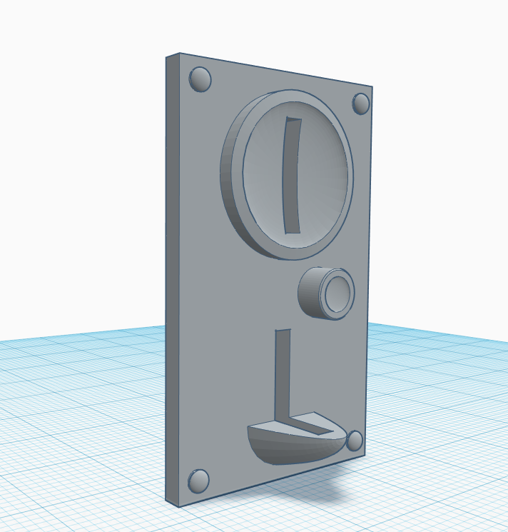
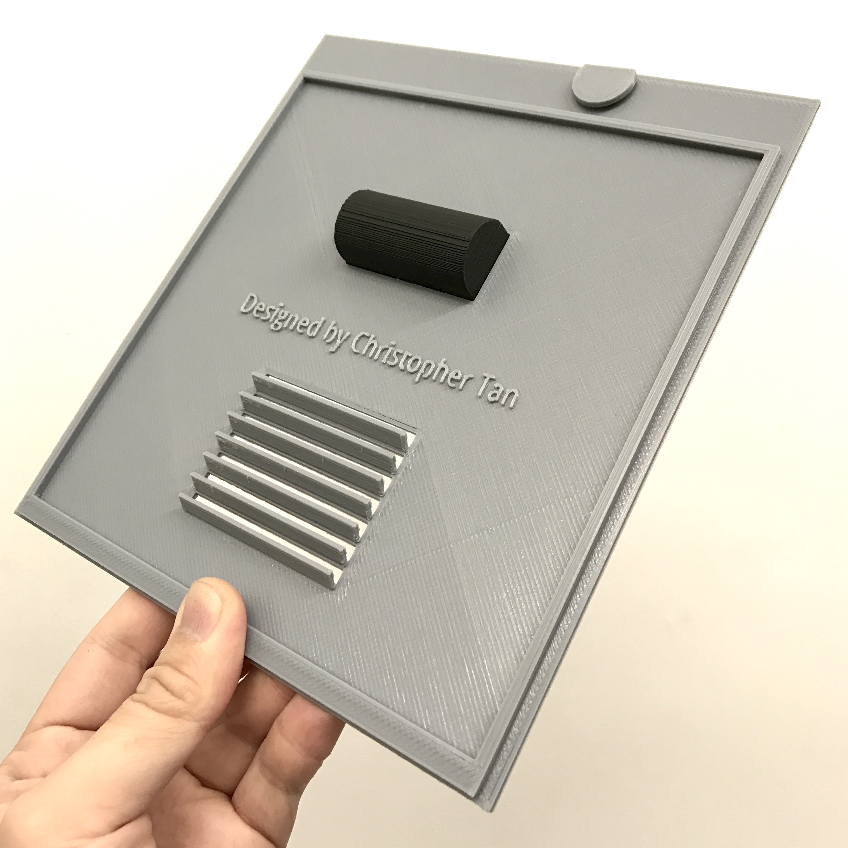
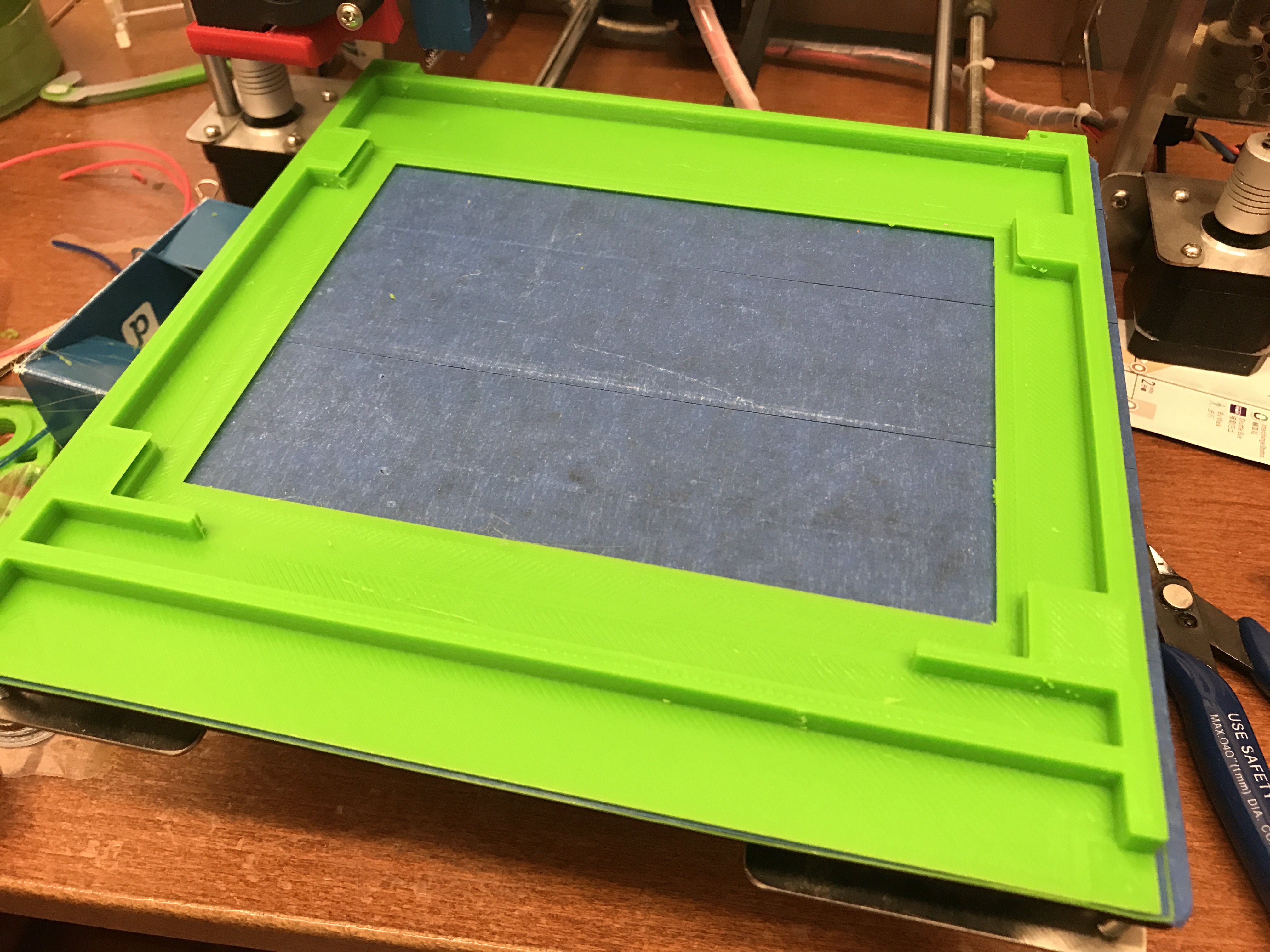
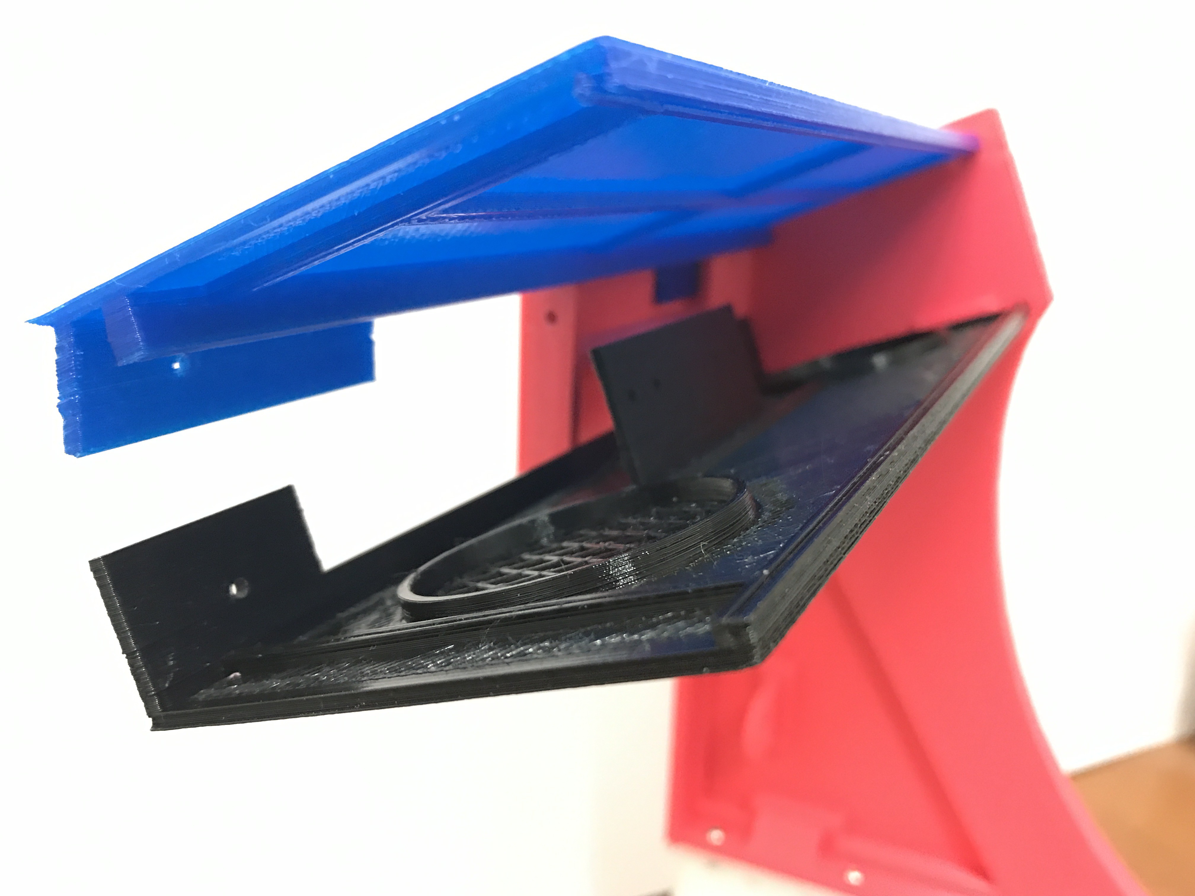
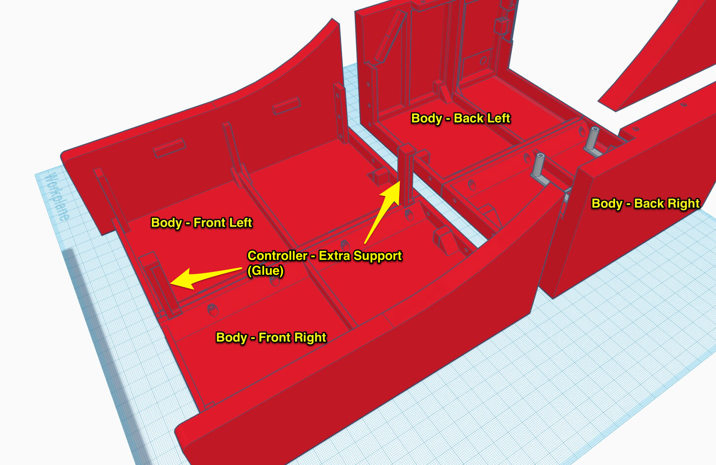
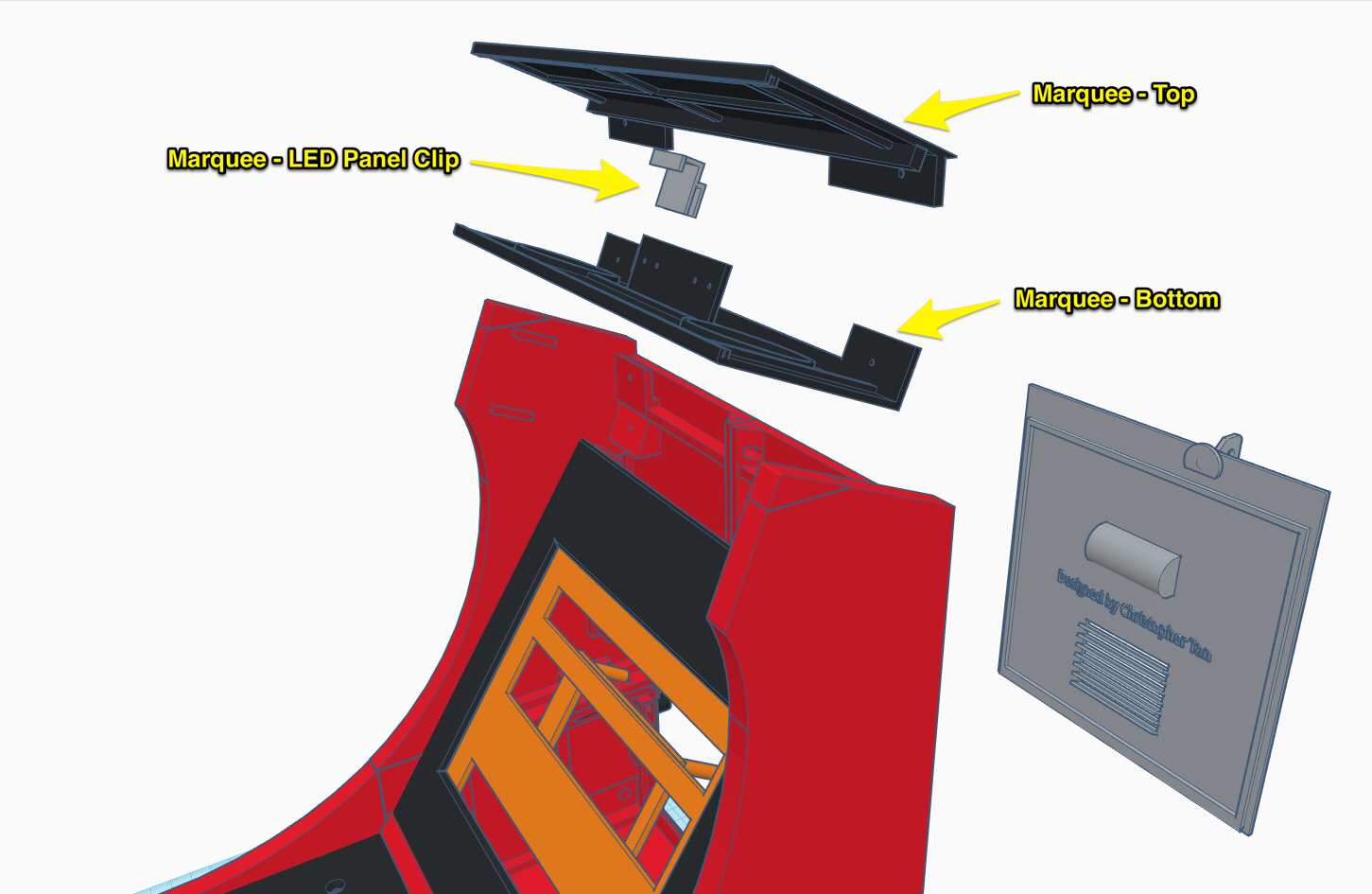
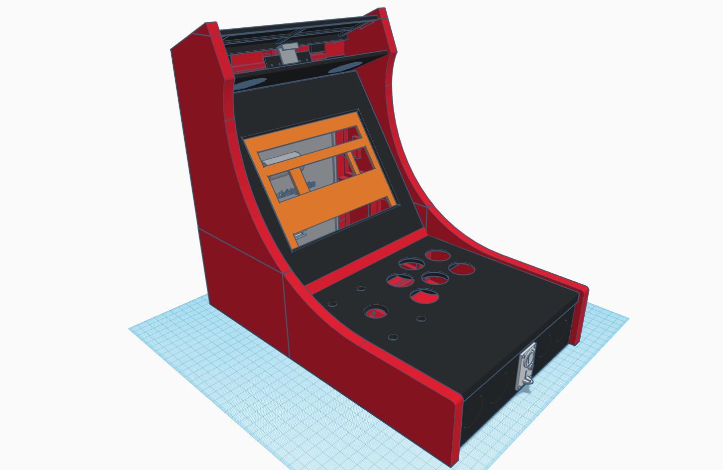
Here are more photos of the 3D models I created for this project.

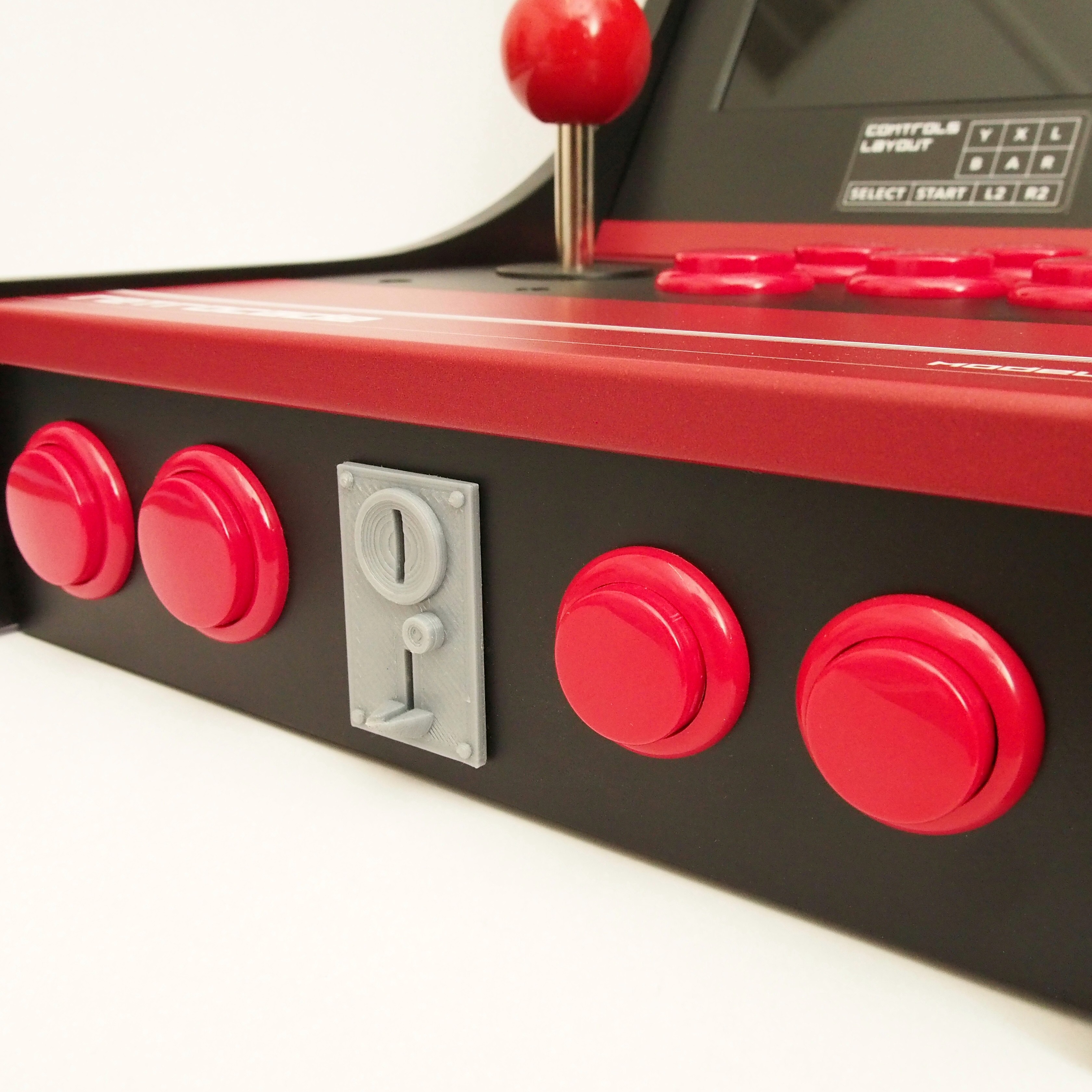
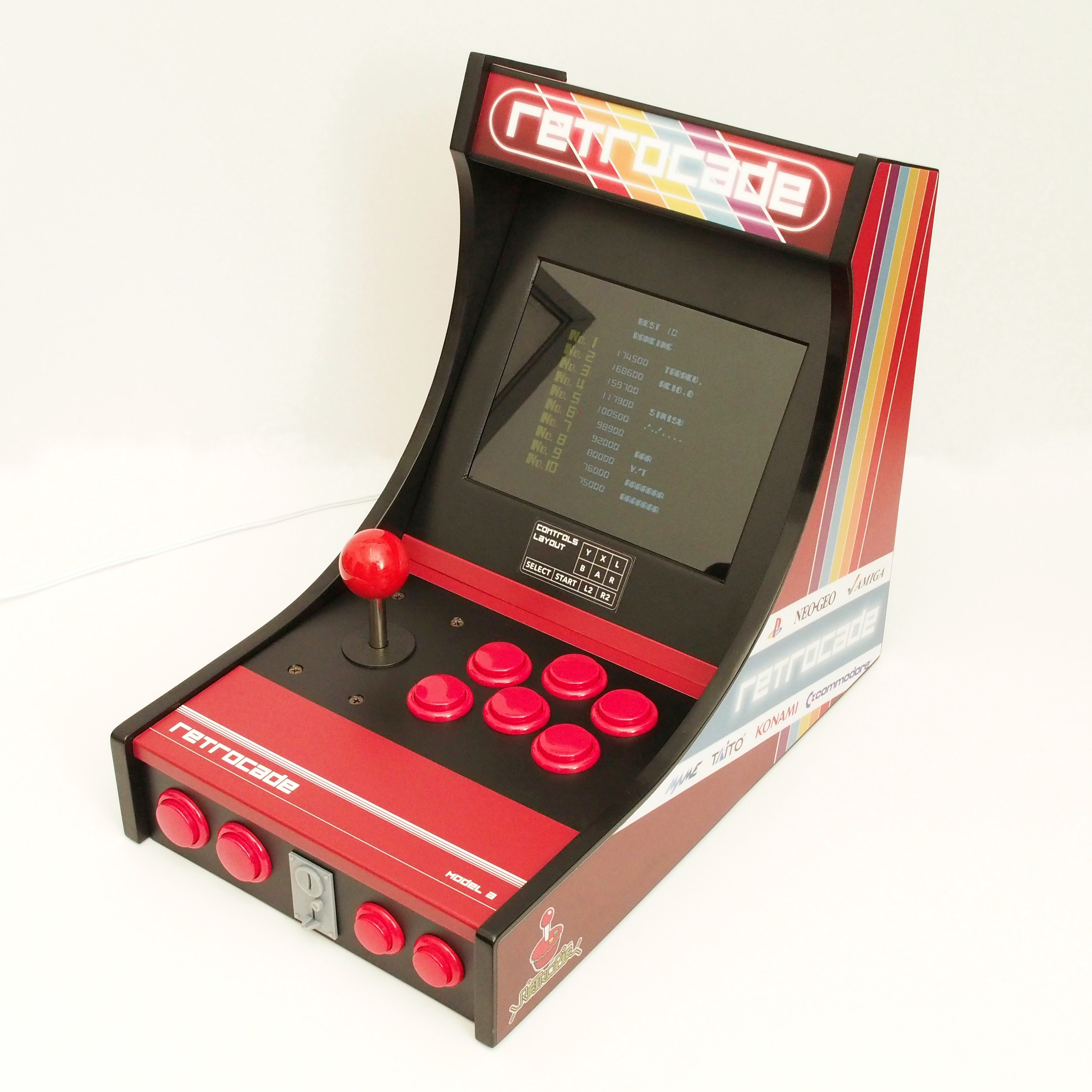
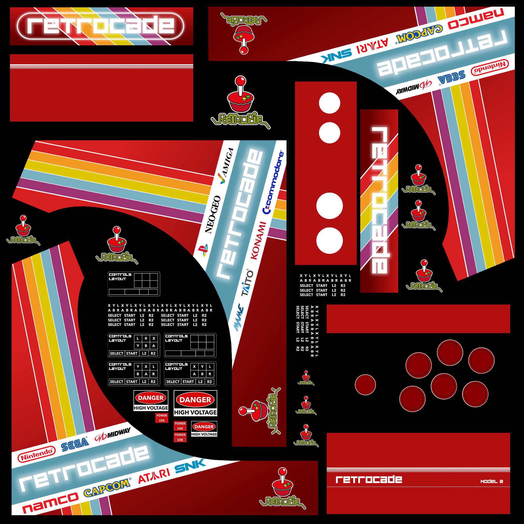
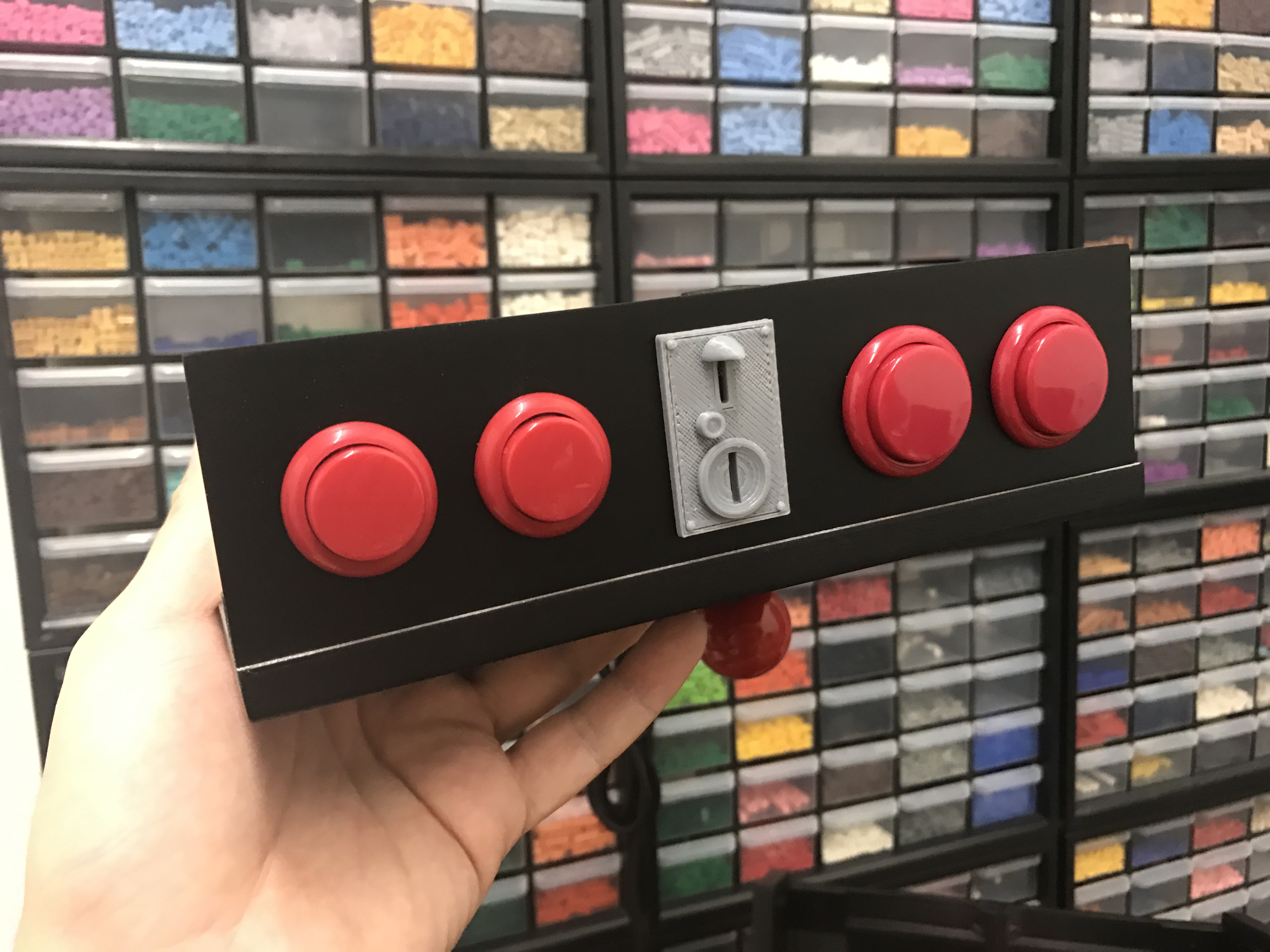
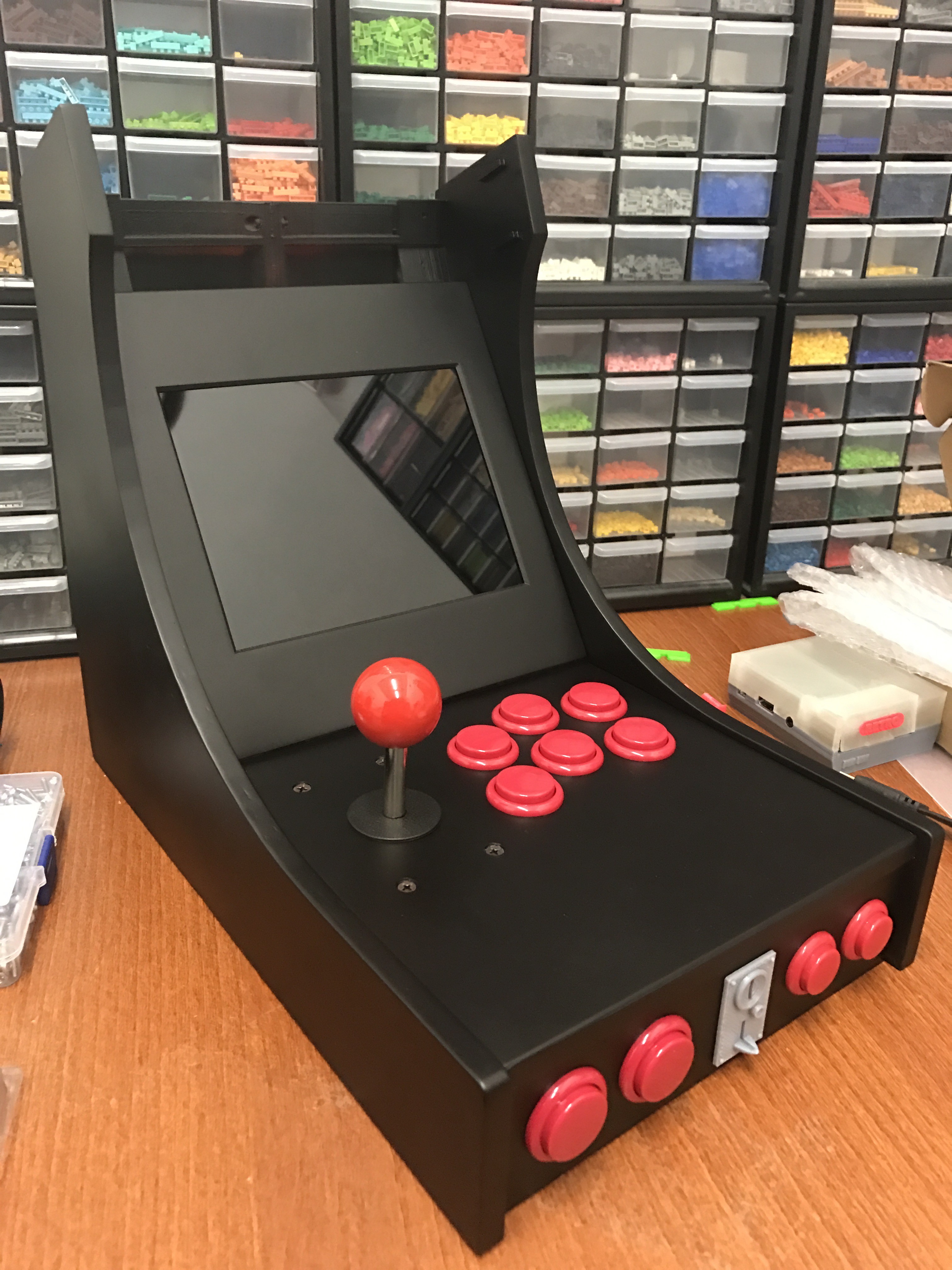
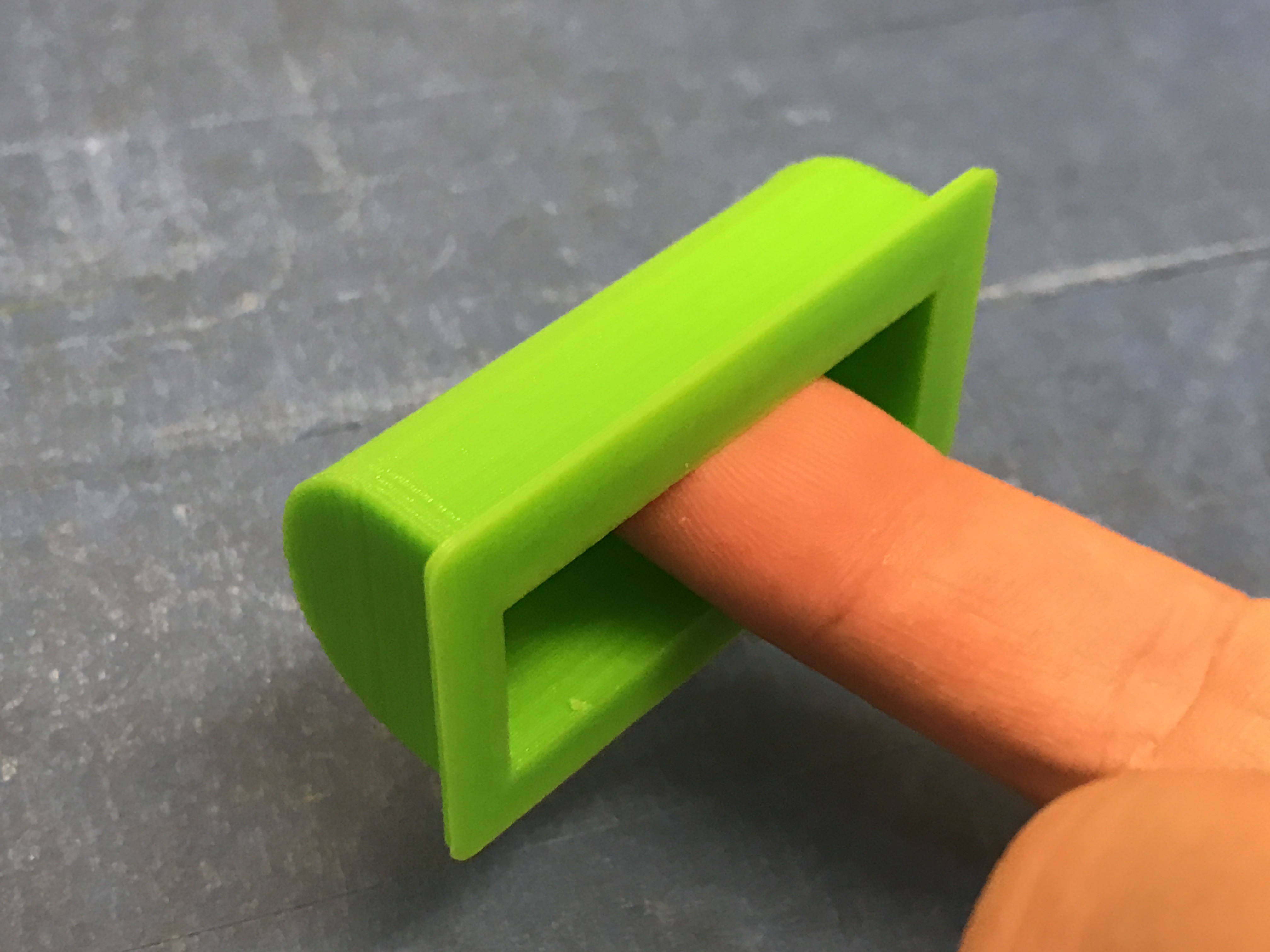
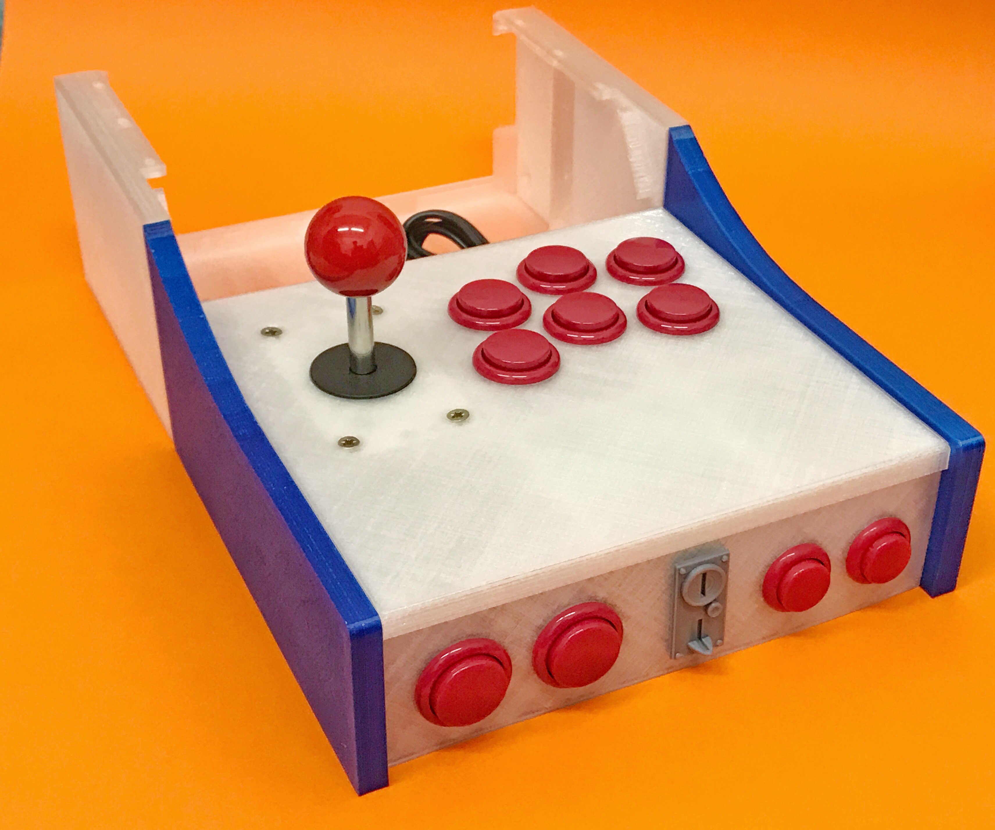
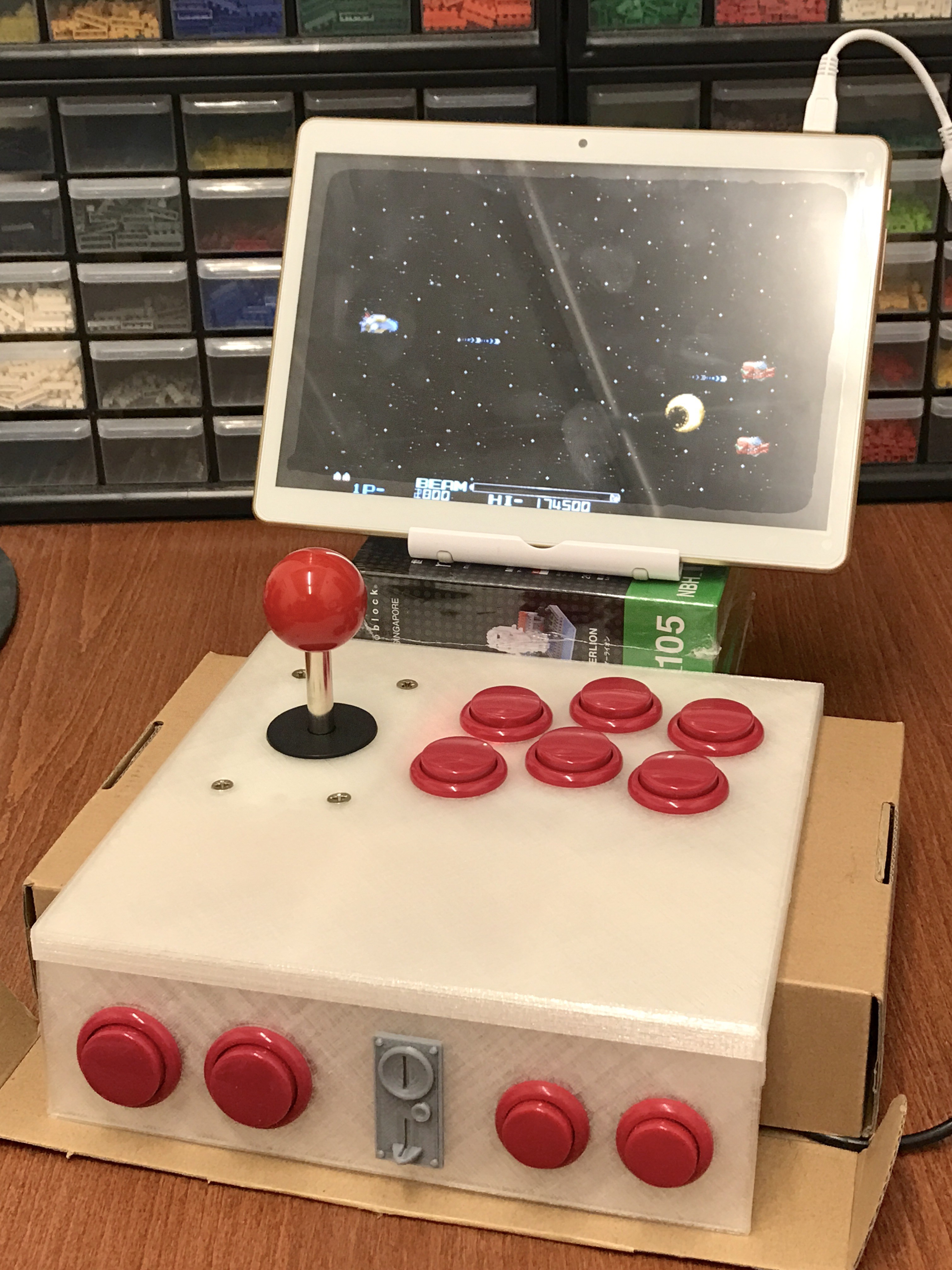
This is the coin slot. I know it's just decor, but I love adding detail to my project =)

Coin Slot

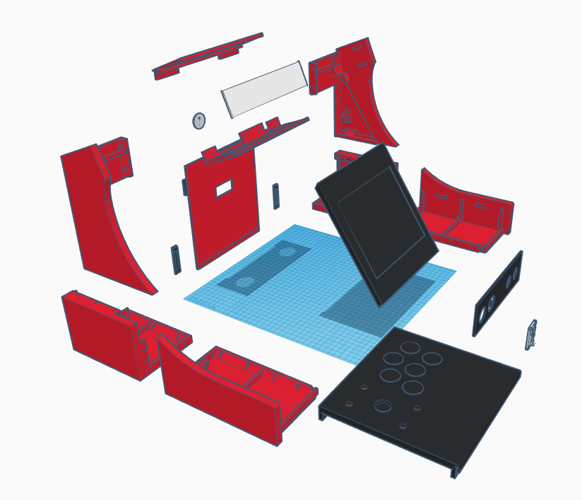
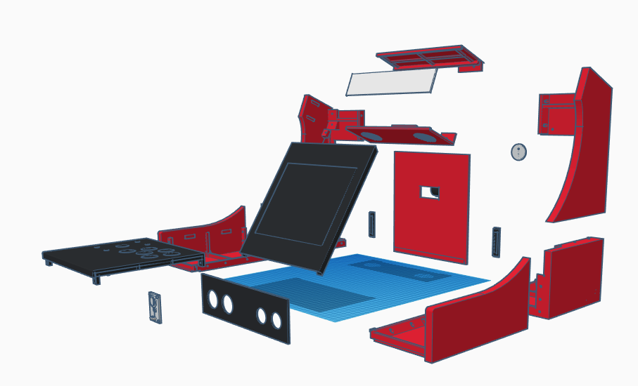
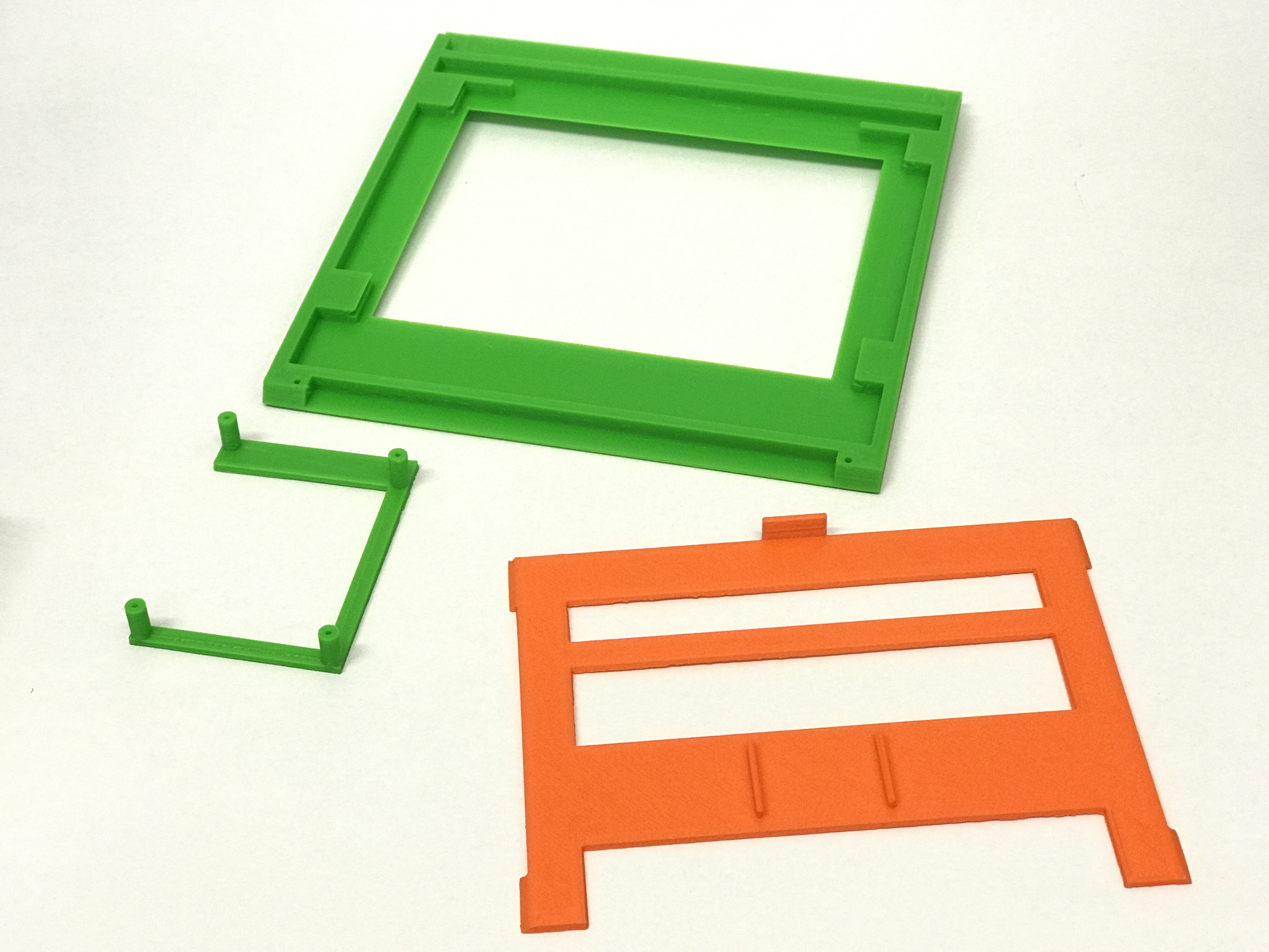
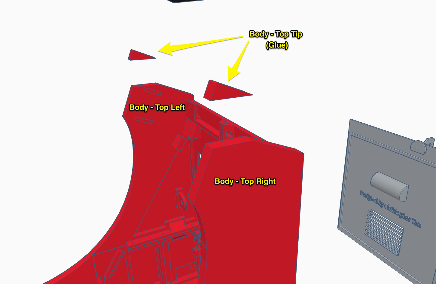
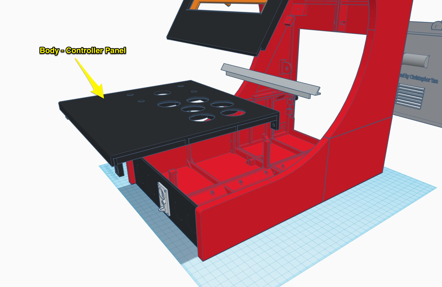
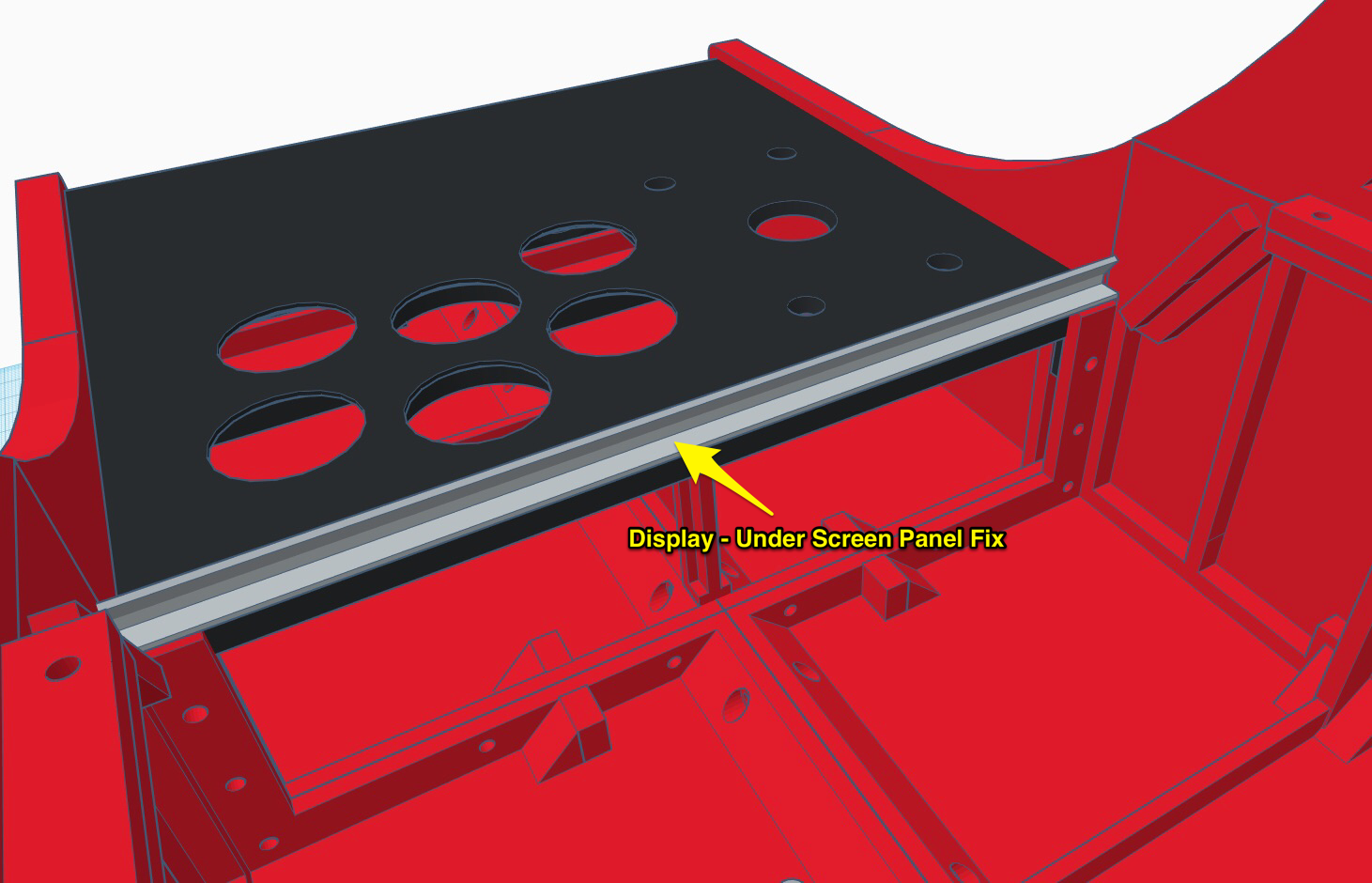
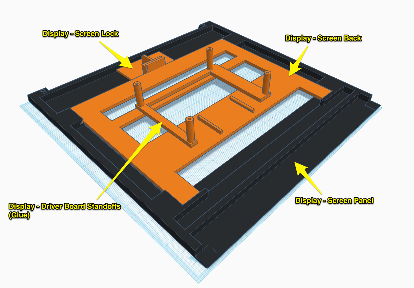
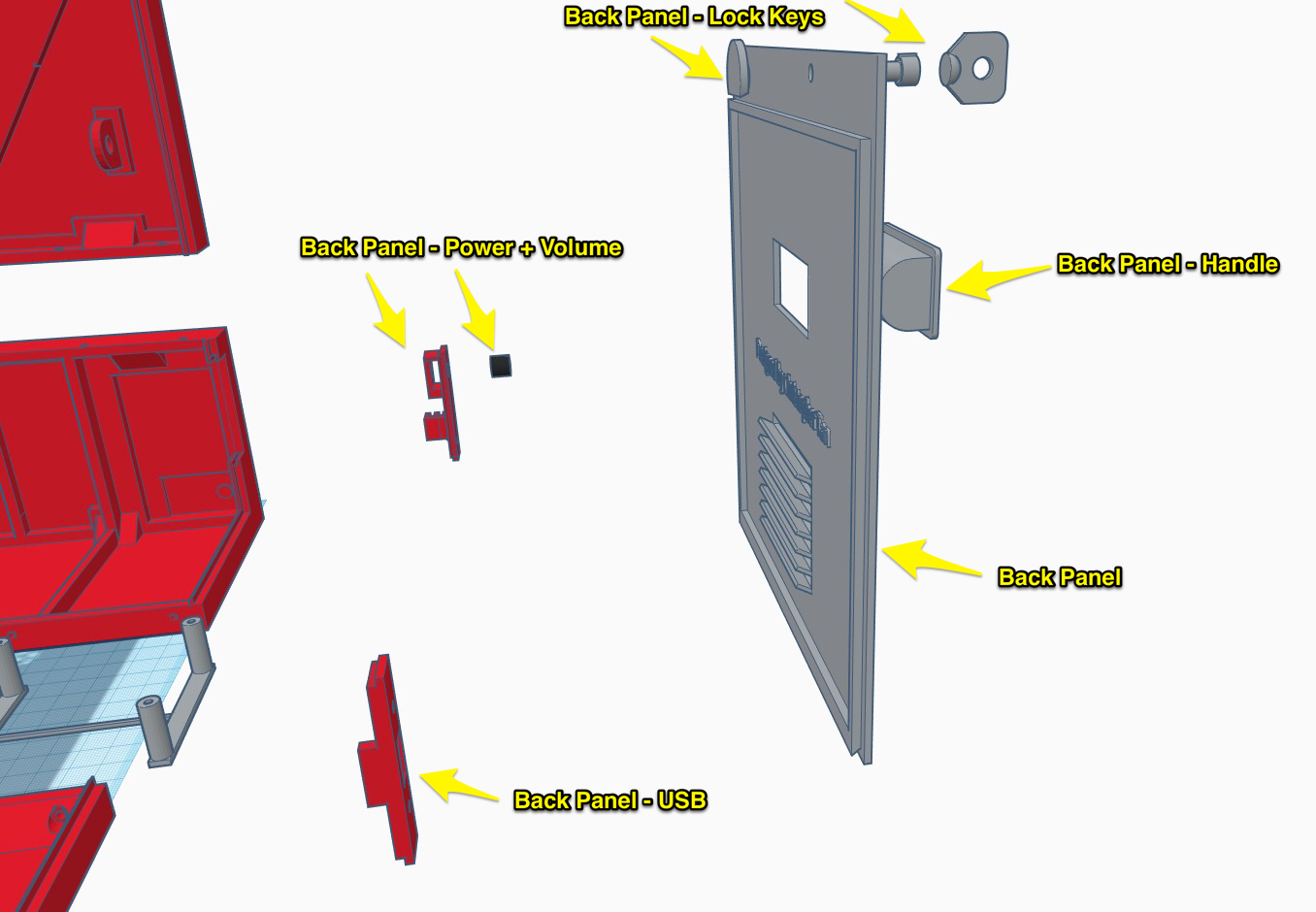
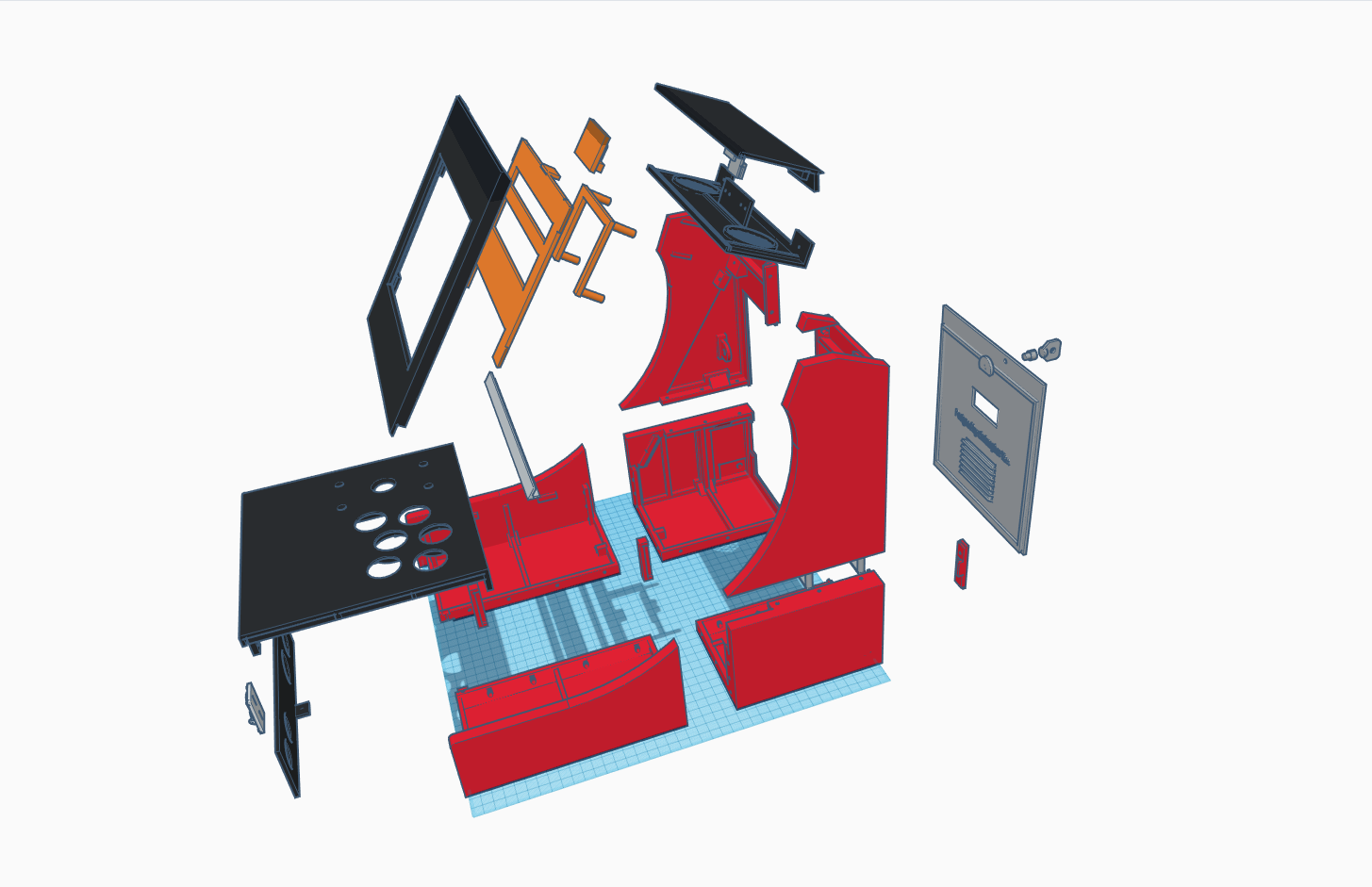
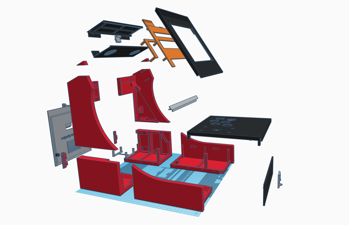
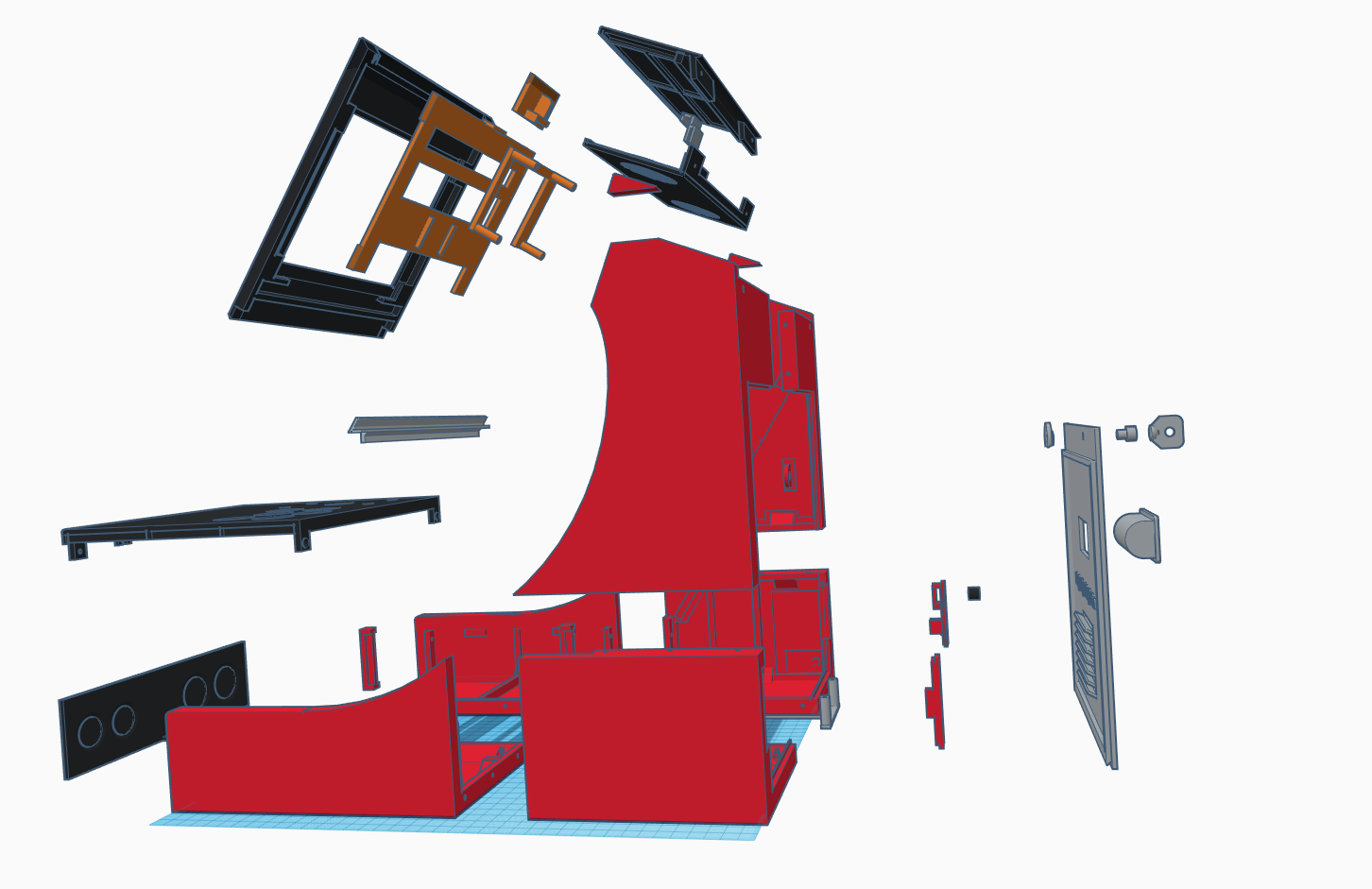
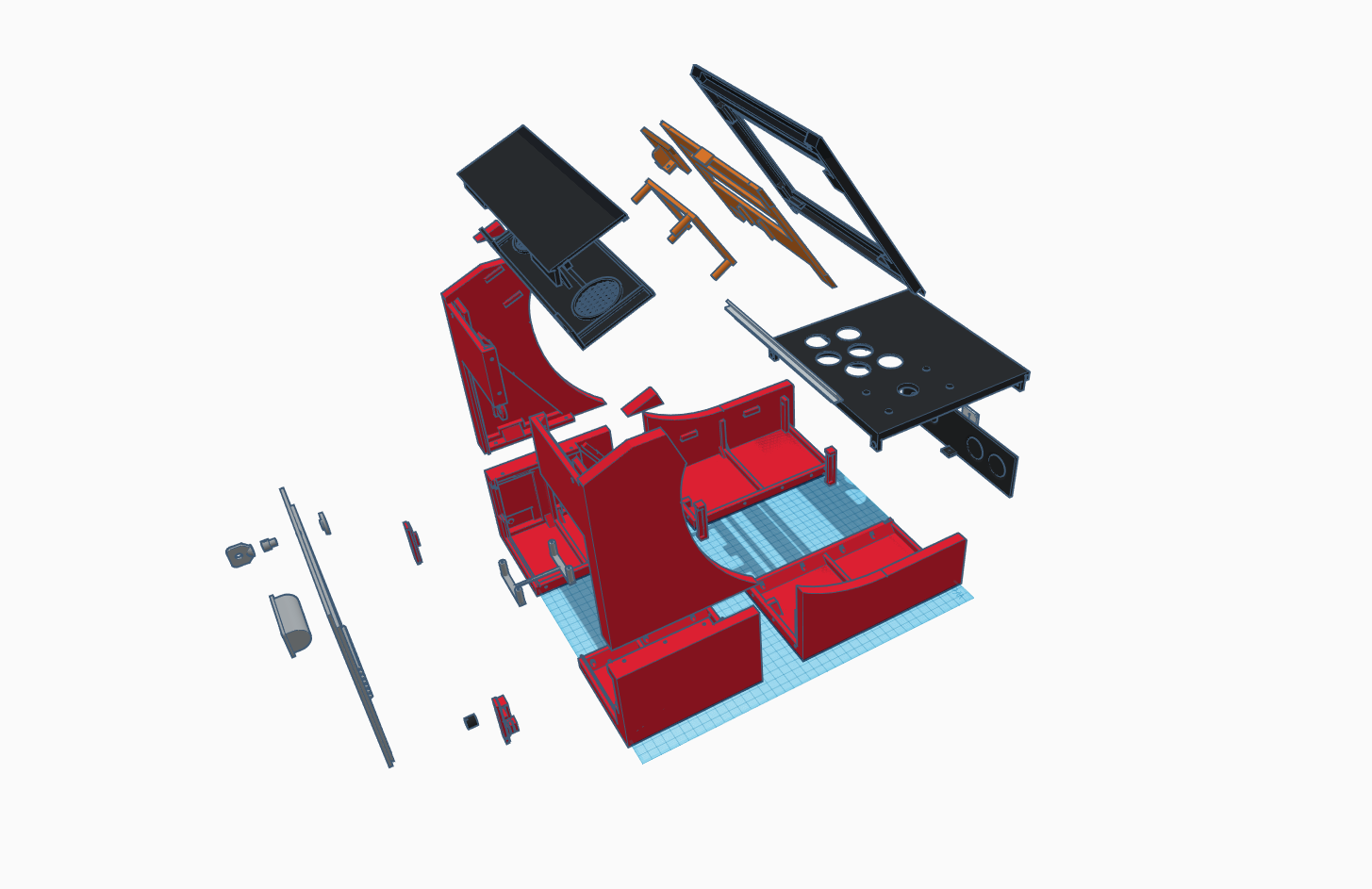
Here are some exploded views of all the pieces.

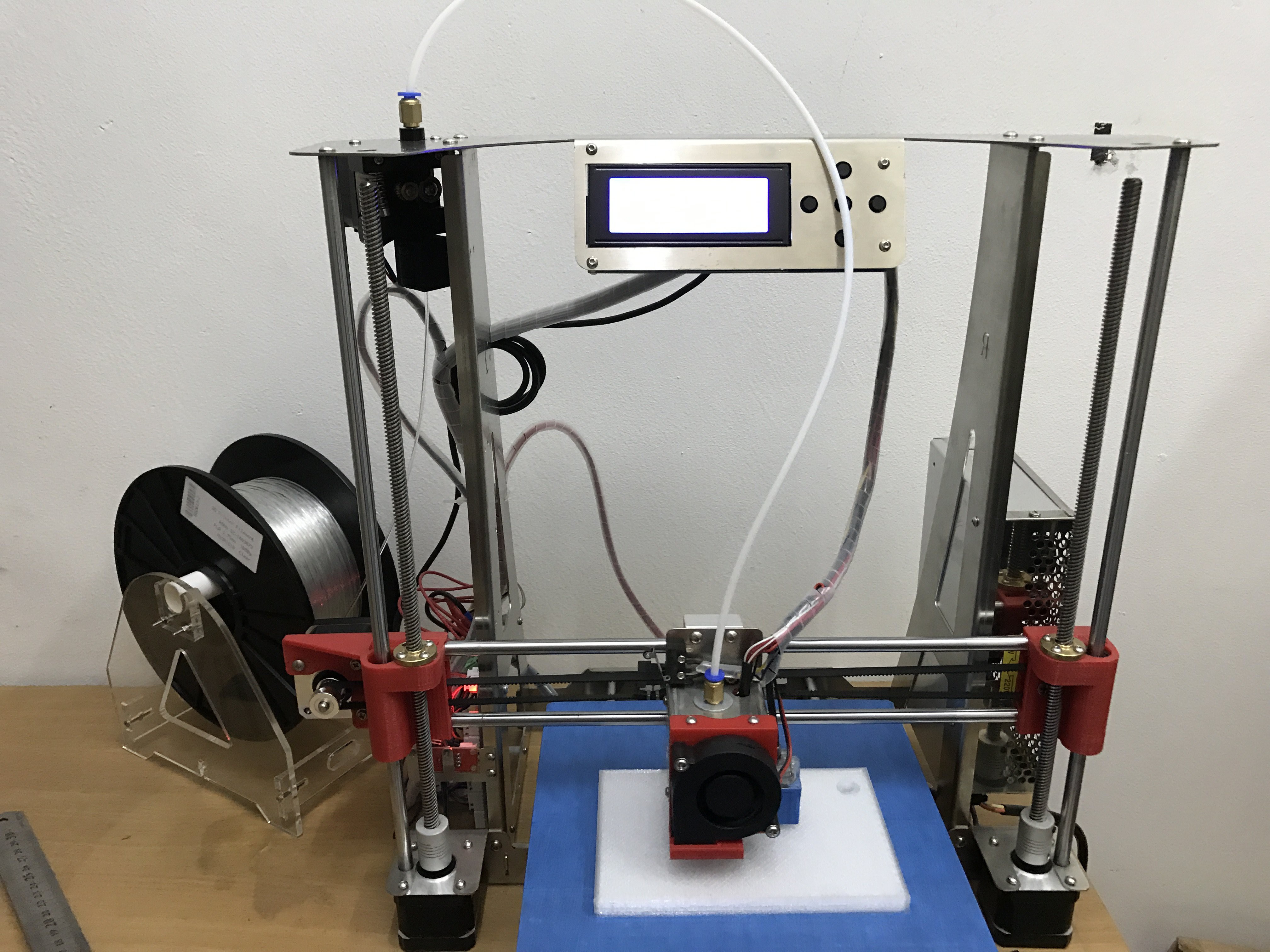
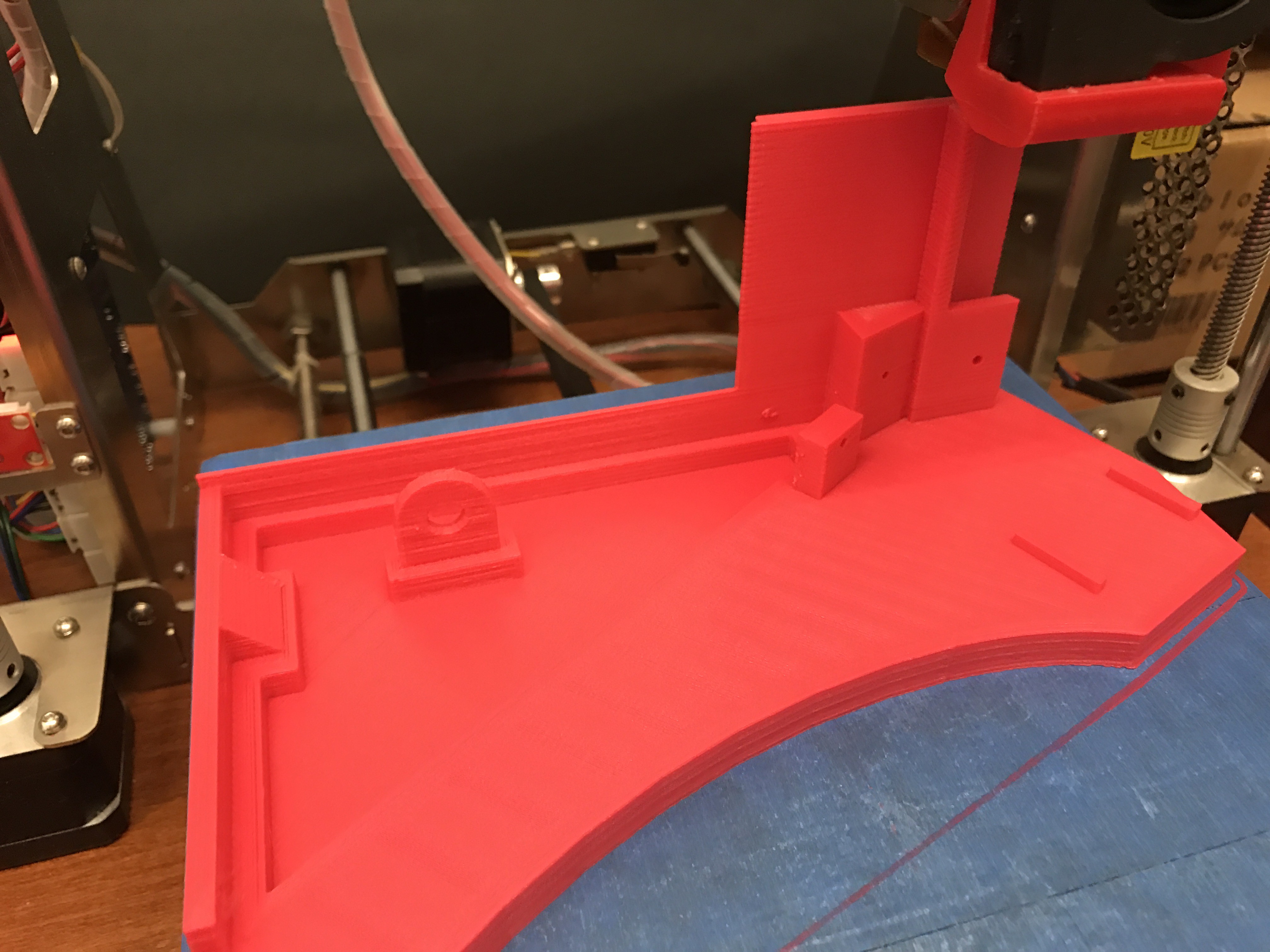
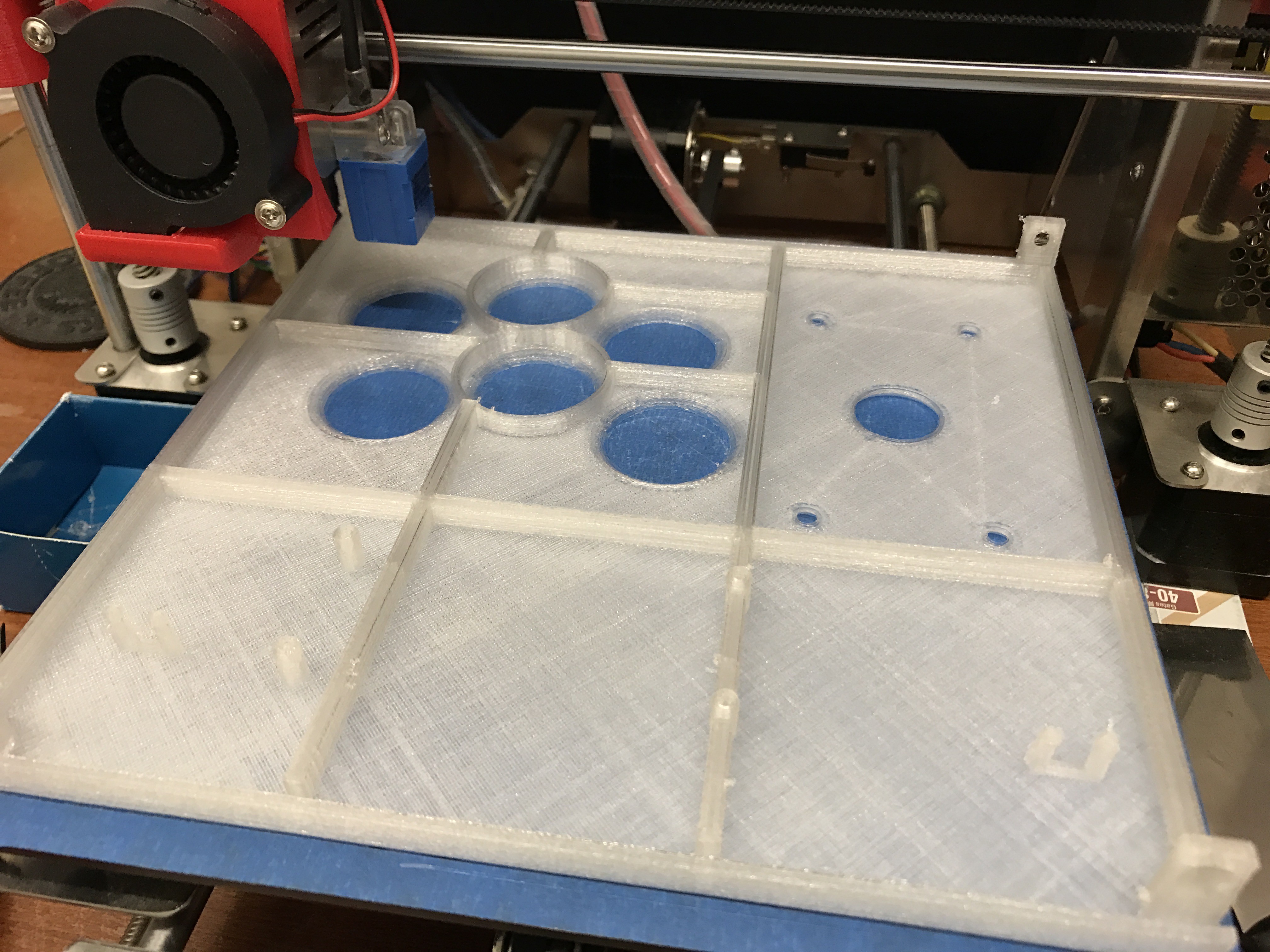
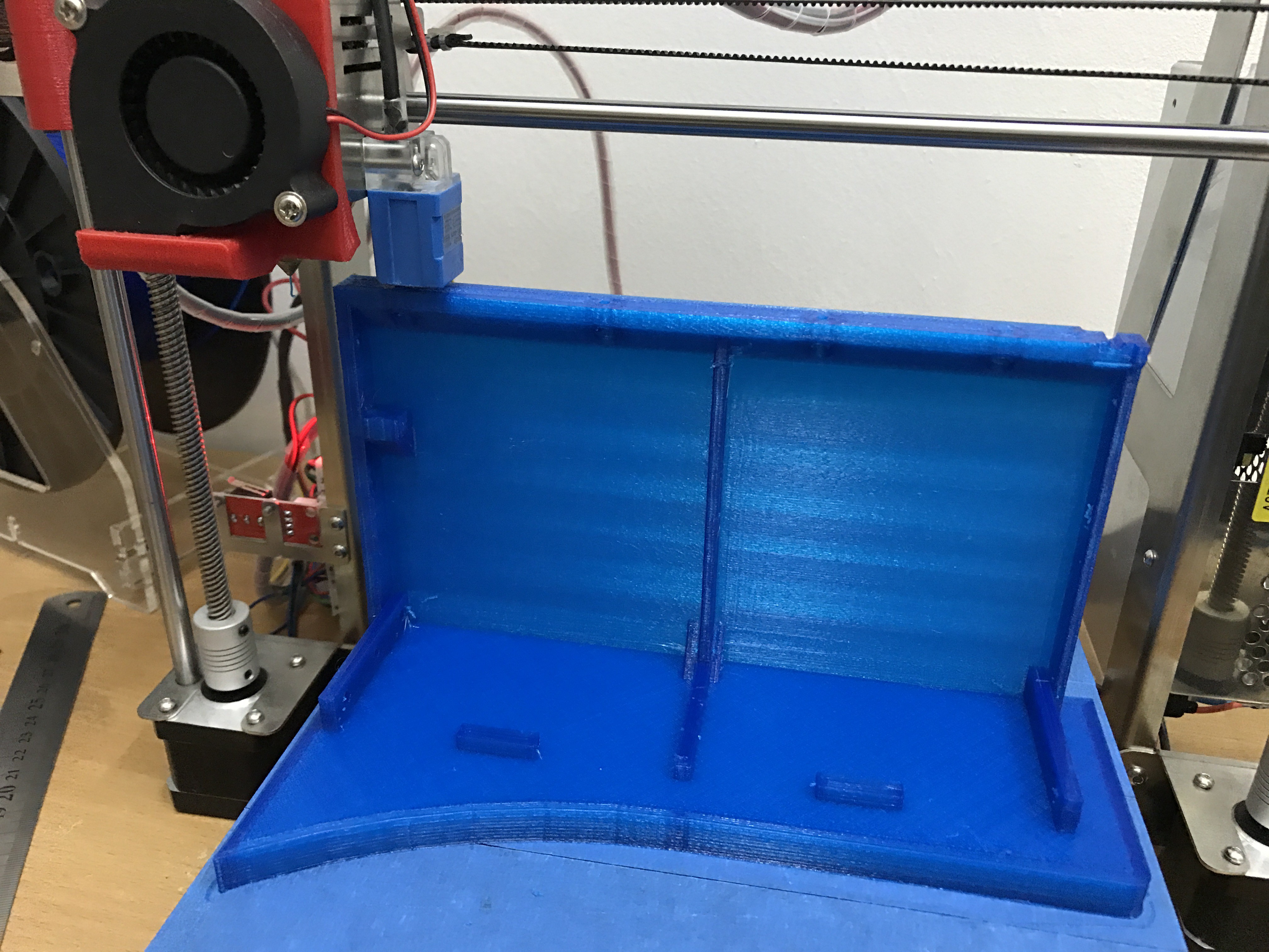
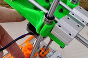
I am doing all the 3D printing on my Zonestar P802QA (based on Prusa i3).

RetrocadeArtwork.pdf

I printed this at 60cm x 60cm.

Adobe Portable Document Format - 3.88 MB - 04/20/2017 at 15:58

Preview
Download

body_-_front_left.stl

Body - Front left

Standard Tesselated Geometry - 126.84 kB - 04/04/2017 at 02:18

Download

body_-_front_right.stl

Body - Front Right

Standard Tesselated Geometry - 129.87 kB - 04/04/2017 at 02:18

Download

body_-_front_panel.stl

Body - Front Panel

Standard Tesselated Geometry - 116.68 kB - 04/04/2017 at 02:18

Download

coin_slot.stl

Front Panel - Coin Slot

Standard Tesselated Geometry - 530.75 kB - 04/04/2017 at 02:18

Download

View all 26 files

View all 13 components

  • Completed!

    Christopher Tan03/17/2017 at 15:42 0 comments

    Finally, the audio amplifier arrived in the mail! So, soldered all the connections, plugged in the power to Raspberry Pi's GPIO pins and off we go! So, everything in this project (display, sound, lights) are powered from the RPi.

    Designed the removable panel to allow the amplifier to be mounted and you can adjust the volume using a small knob.

    And this is how the back of the arcade machine looks like now in the final design.

    Here's the full video of the completed project.

    At long last, after what seems like forever ... Hahahaaa!

  • Stickers Are Ready!

    Christopher Tan03/16/2017 at 12:35 1 comment

    Finally got the vinyl sticker back from the printers!

    Cutting and pasting stickers!

    Here it is, now it looks fully complete for the first time! The only thing left to do is to integrate the audio amplifier once it arrives in the mail.

    In the mean time, here's a proper video of my arcade machine =)

    And photos, lots of photos! Enjoy! =D ... Please excuse the washed out screen as I was shooting with flash lighting.

    Here's one taken without flash so you can see the screen properly and I also turned on the marquee backlight for this.

  • Finishing Touches 1

    Christopher Tan03/13/2017 at 01:50 0 comments

    I just realised I forgot to put in ventilation holes, so I redesigned and reprinted the back panel. They were designed this way so that the insides of the machine remains unseen.

    Soldered the LEDs together for the marquee lighting. They are being powered from USB, so I will just plug this into the Raspberry Pi 3.

    A quick test to see if it would be bright enough to backlight the marquee. I think it's fine, don't want to be blinded by it ... Hahaha

    Bought these giant anti-slip pads from Daiso. Will stick these under the arcade machine to keep it from moving around.

    The micro USB male to female extension cable just arrived, so I designed and printed this piece. It will slot into the back of the machine so that I can easily connect/disconnect the power supply to the RPi.

    Lastly, I put together all the artwork I created and sent it to a commercial printer to get them printed as vinyl sticker.

    Hopefully, all my remaining parts (speaker, amplifier, USB-A extension cable) arrive this week and I should be able to fully complete my build this weekend! =D ... Can't wait!

  • Assembly

    Christopher Tan03/08/2017 at 06:37 0 comments

    Now for the fun part, finally putting it all together!

    Here are the parts. I know they're not like 100% perfect, but I ran out of primer and didn't want to wait anymore, so here we are ... LOL

    First, putting all the buttons and joystick into the panels!

    Next, we mount the controller panels on the body. Looks good right?

    Now for the display assembly. Here you can see the 8" IPS LCD mounted with the driver board attached behind it.

    Here's how it looks like mounted on the body.

    Finally, the top panels for the marquee are mounted as well and it now looks complete! =D

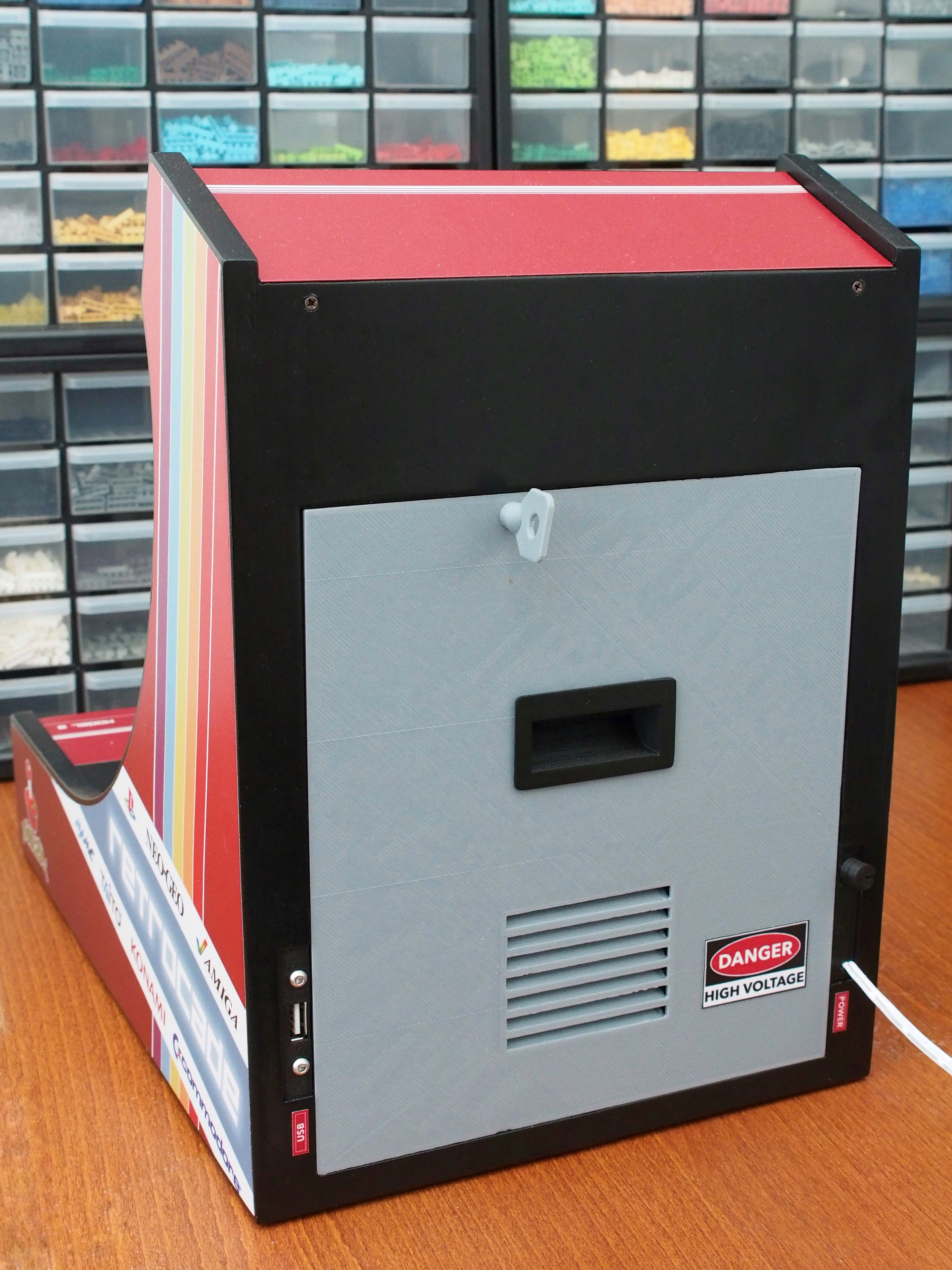
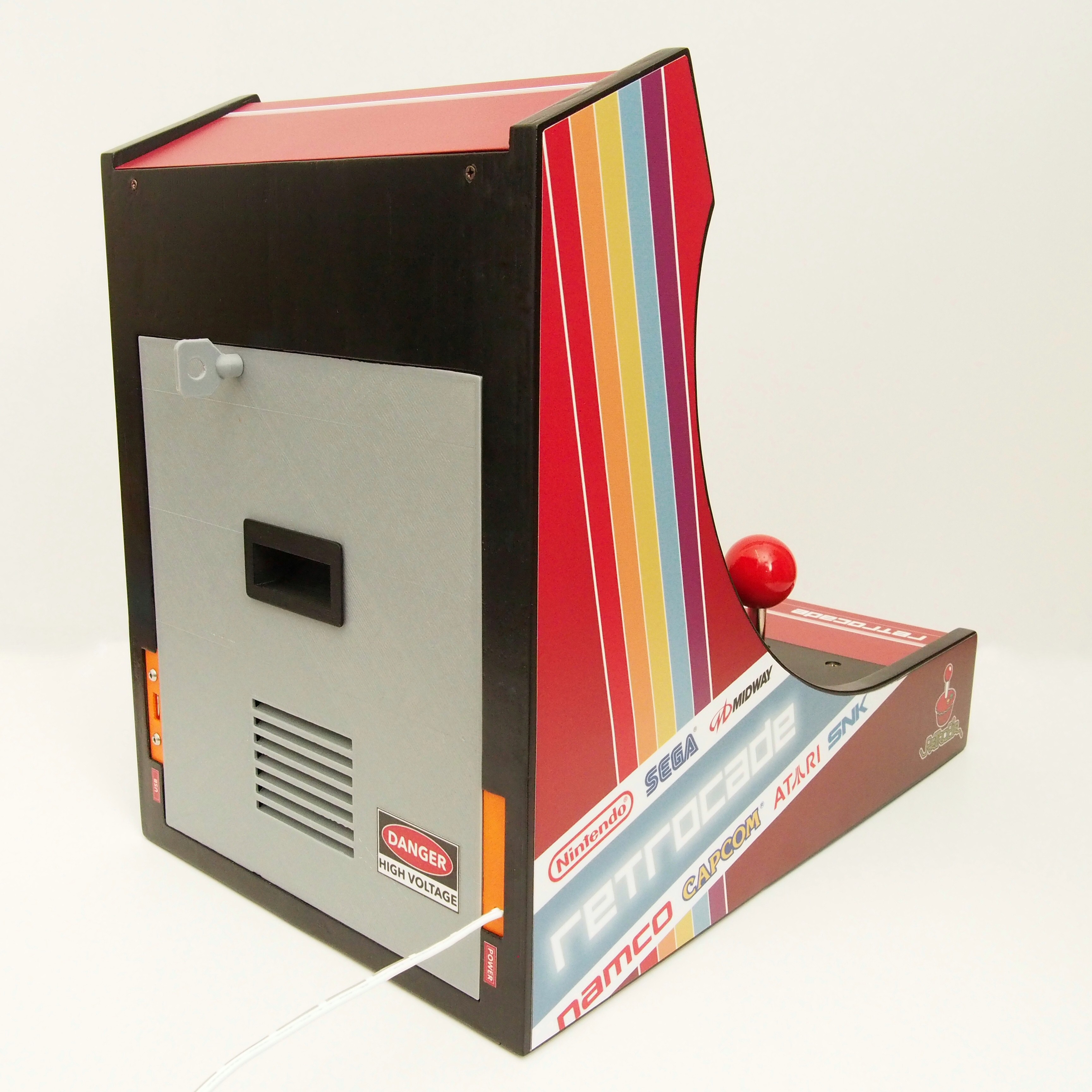
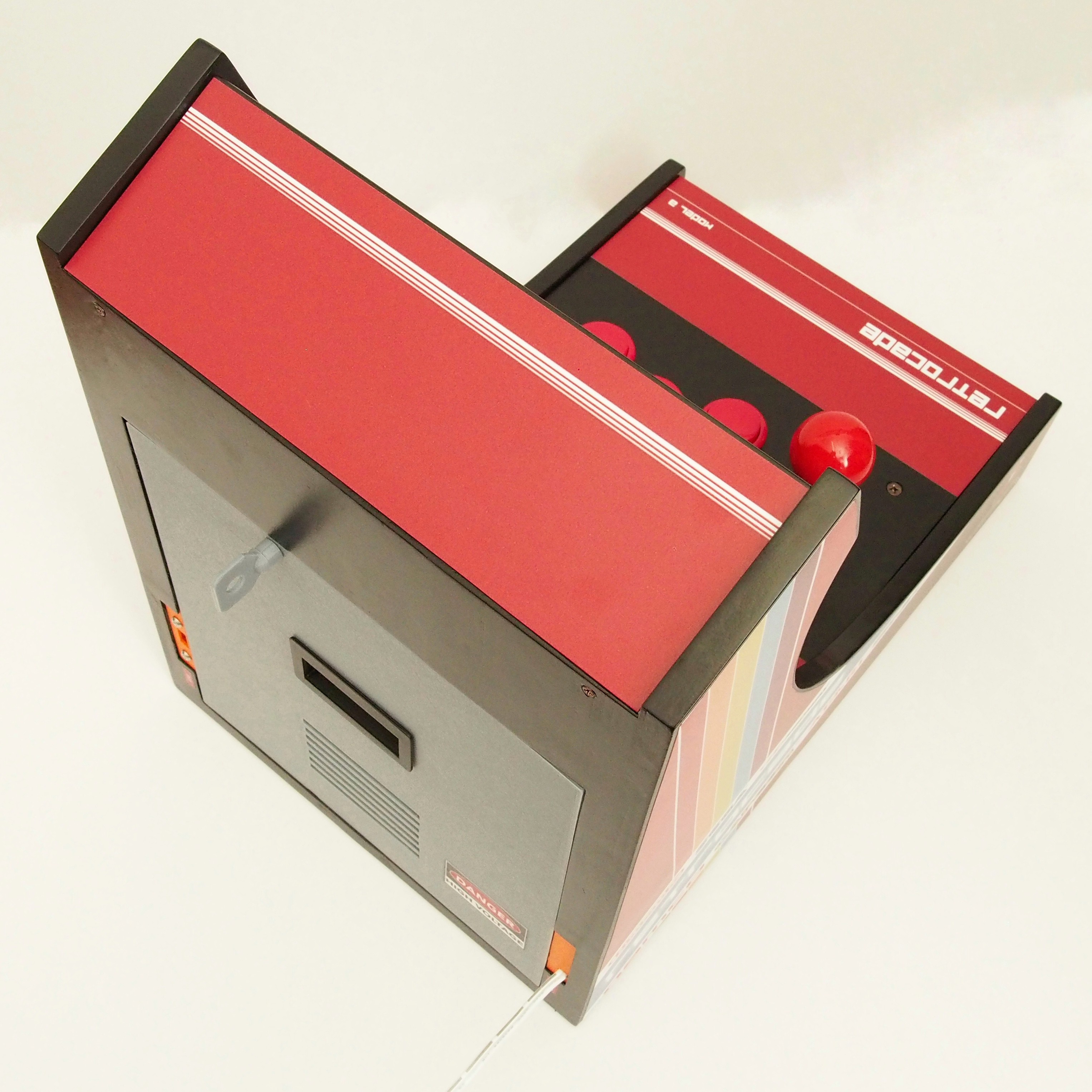
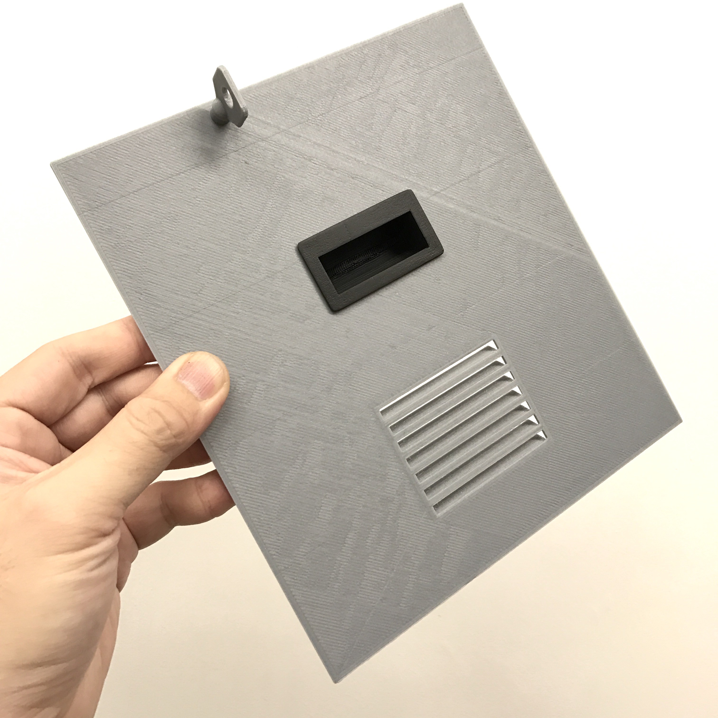
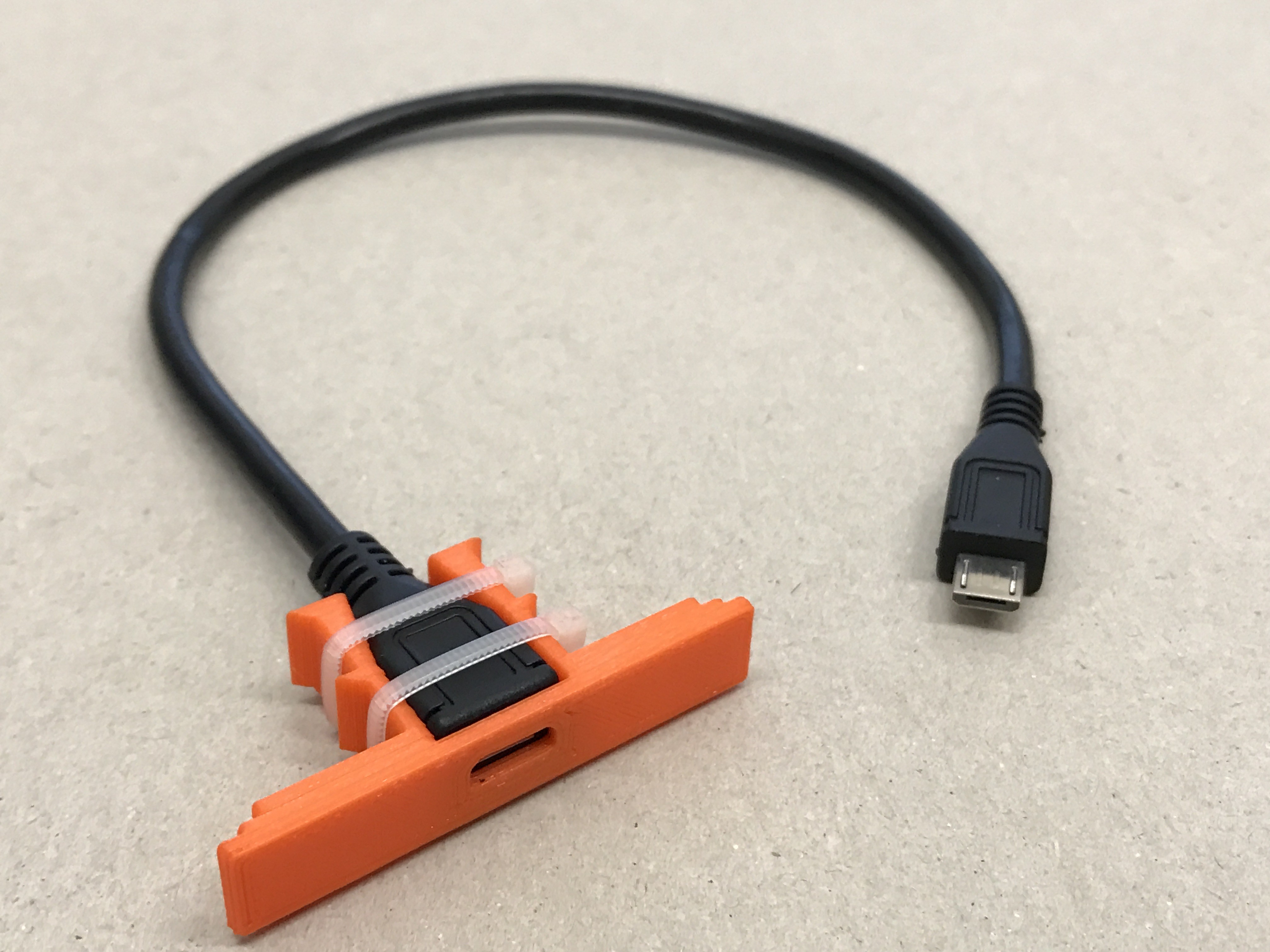
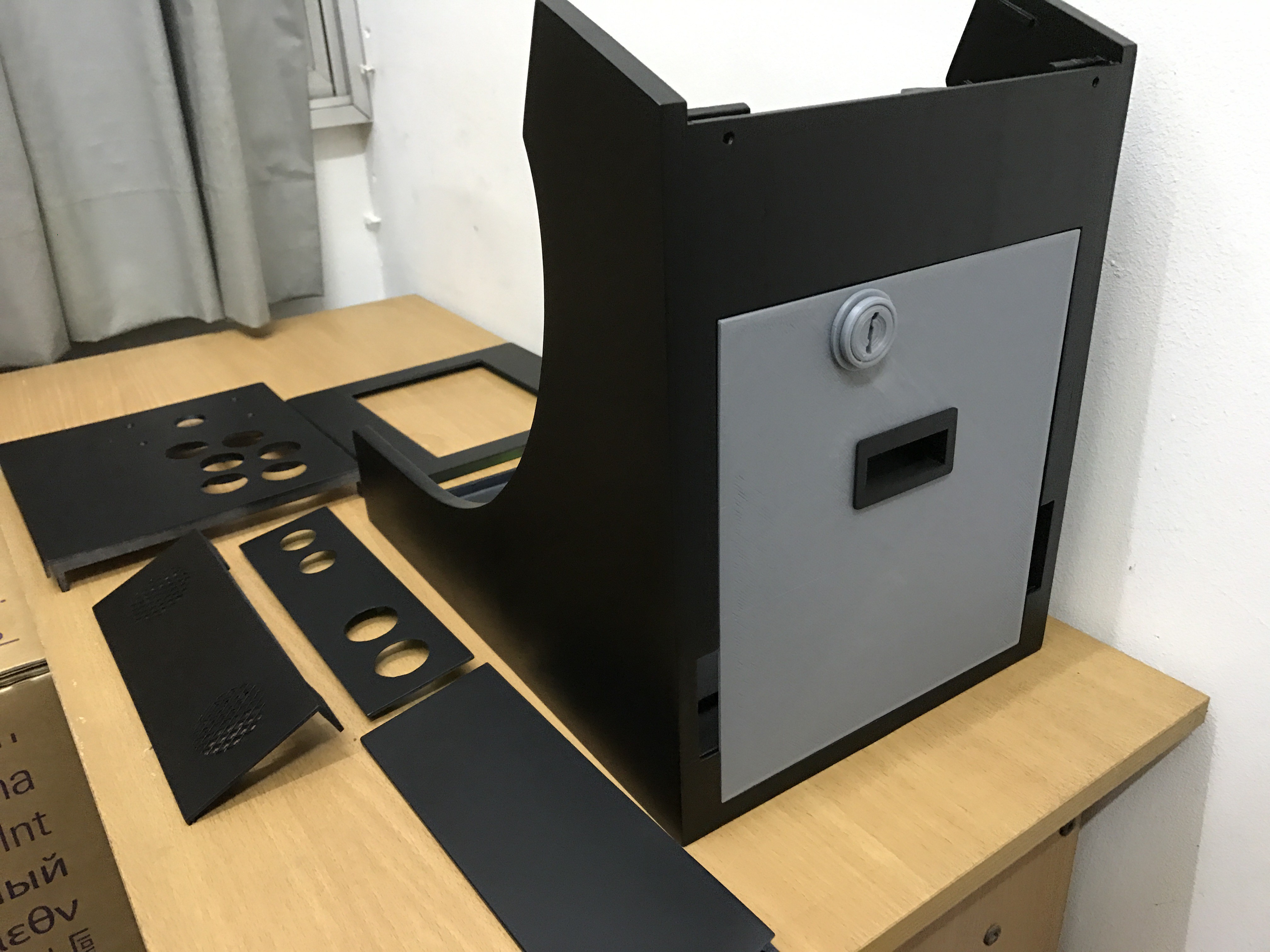
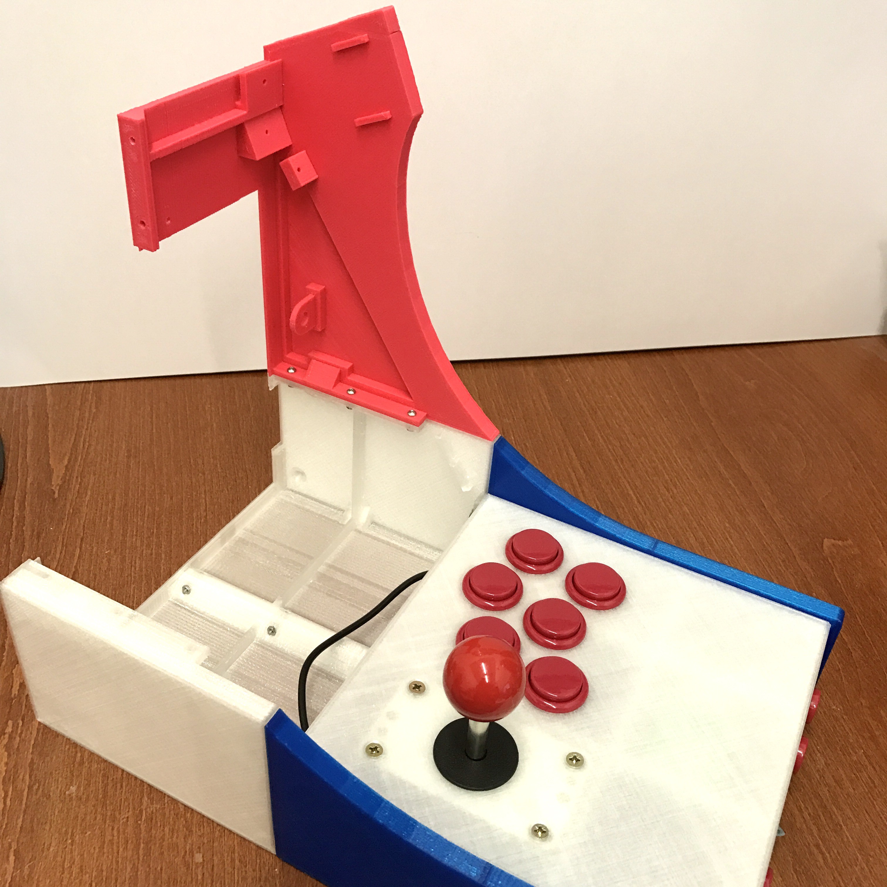
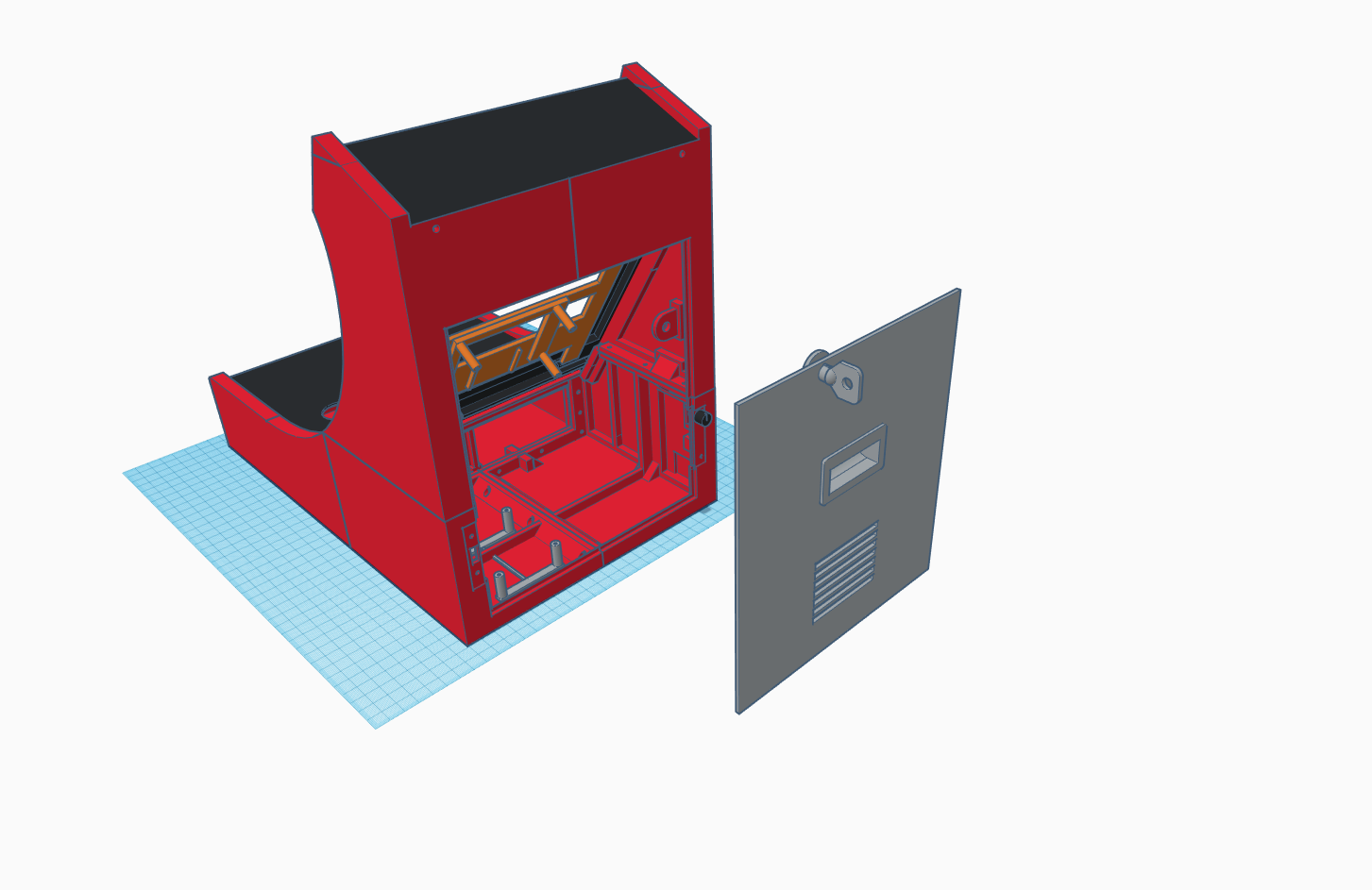
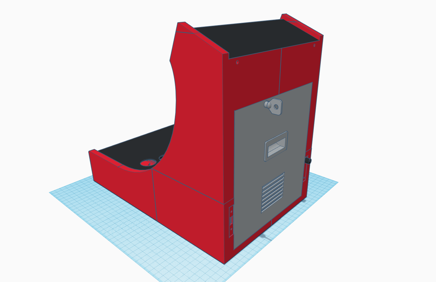
    And here's the back. The back panel's locking mechanism has been modified.

    I also designed some artwork for my arcade. Here I printed it out on my inkjet printer first to see if it looks good. Will be sending these to get it professionally printed on vinyl stickers.

    Here's a video tour! I did this as a Facebook Live broadcast, so you will hear me answering some questions from friends and such :)

  • Painting

    Christopher Tan03/08/2017 at 06:08 0 comments

    All the parts were sprayed with a putty primer and sanded.

    After that, I used matte black paint on all the parts.

    Now to really let it dry ... this is taking forever ...

    Couldn't resist just fitting in the back panel to see if it fits properly. Yes, fits fine, but there was a tiny design flaw with my locking mechanism, so gotta change that.

  • The Display Assembly and Back Panel

    Christopher Tan03/08/2017 at 06:01 0 comments

    Here we move on to the display assembly.

    These 3 pieces will hold the LCD screen and video driver board.

    Mini handle for the back panel.

    The back panel with the handle inserted. Yes, there were some under extrusion issues here.
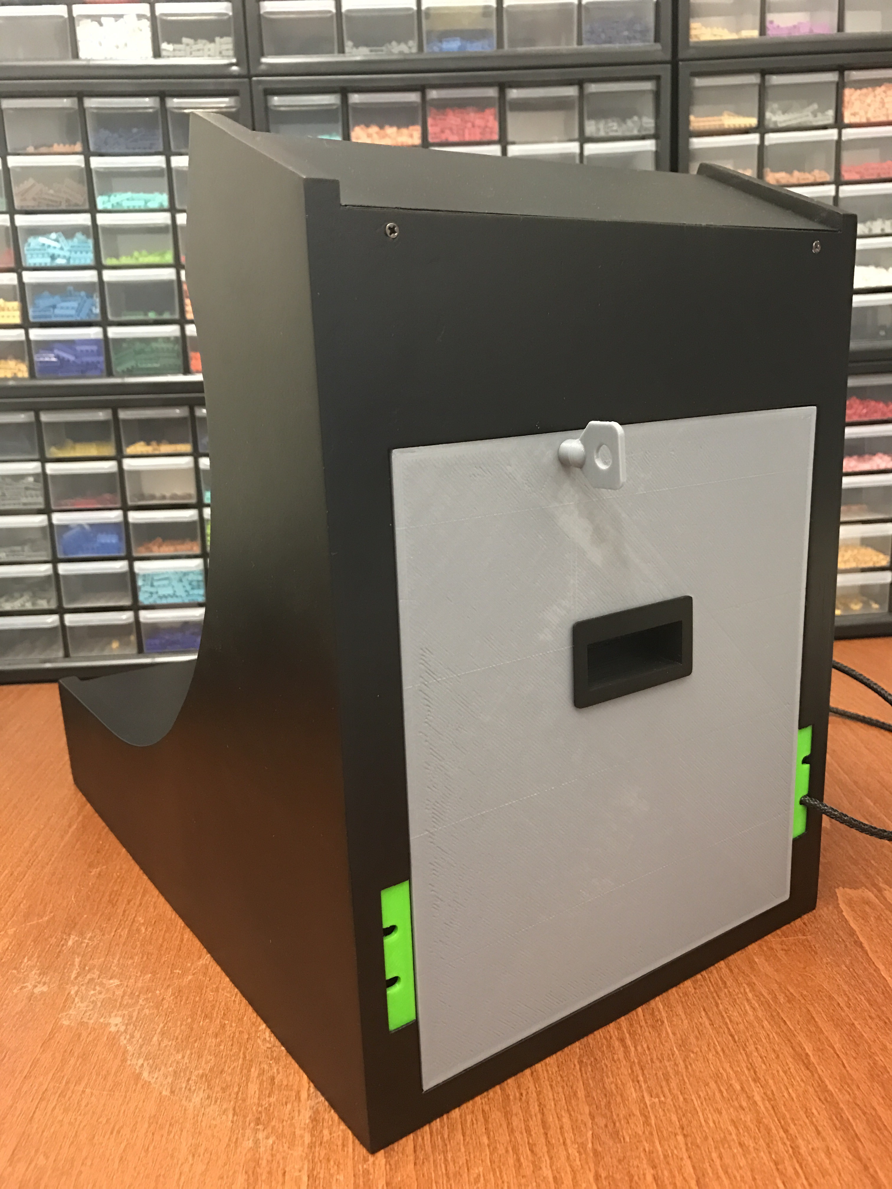
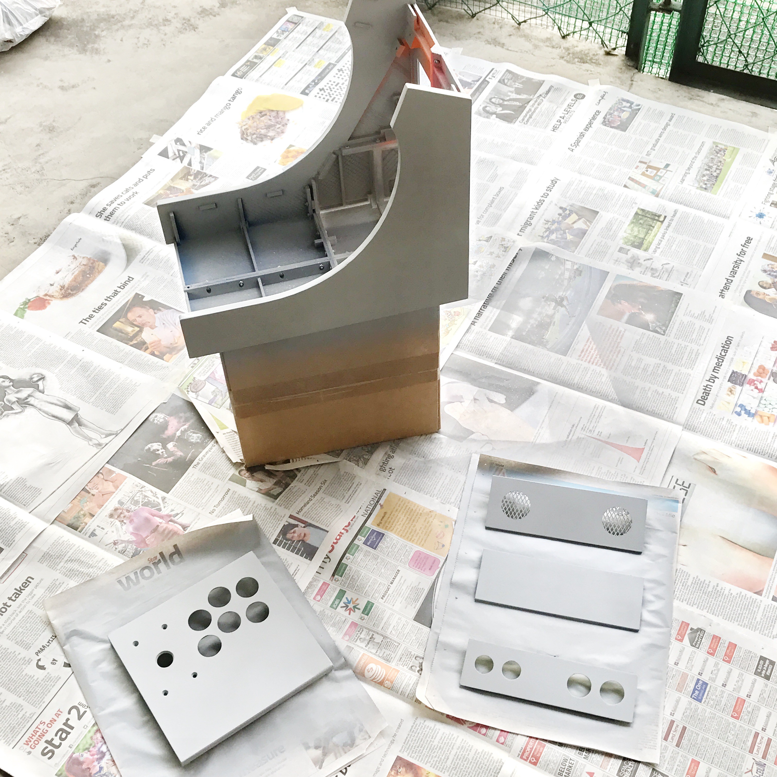
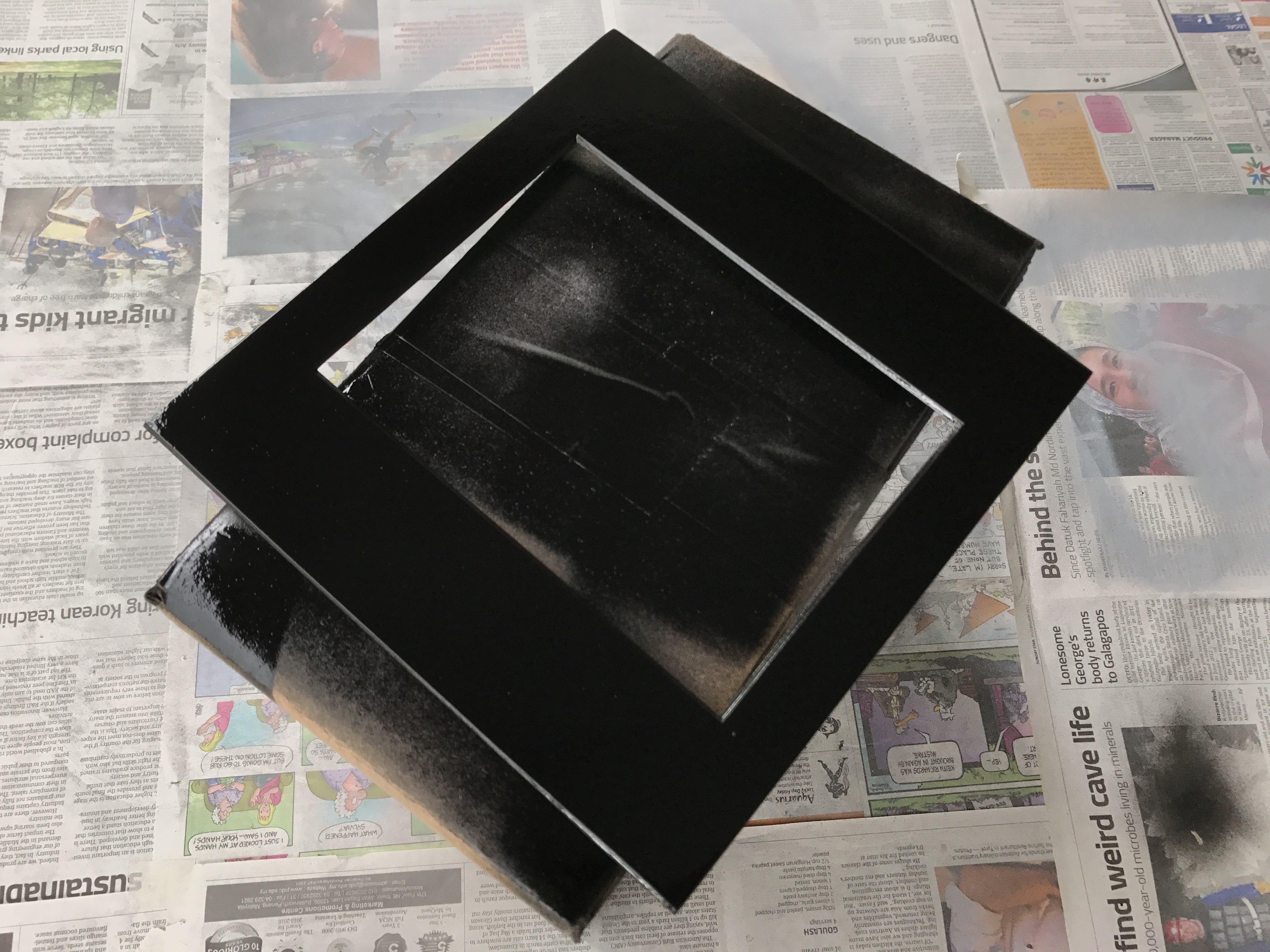
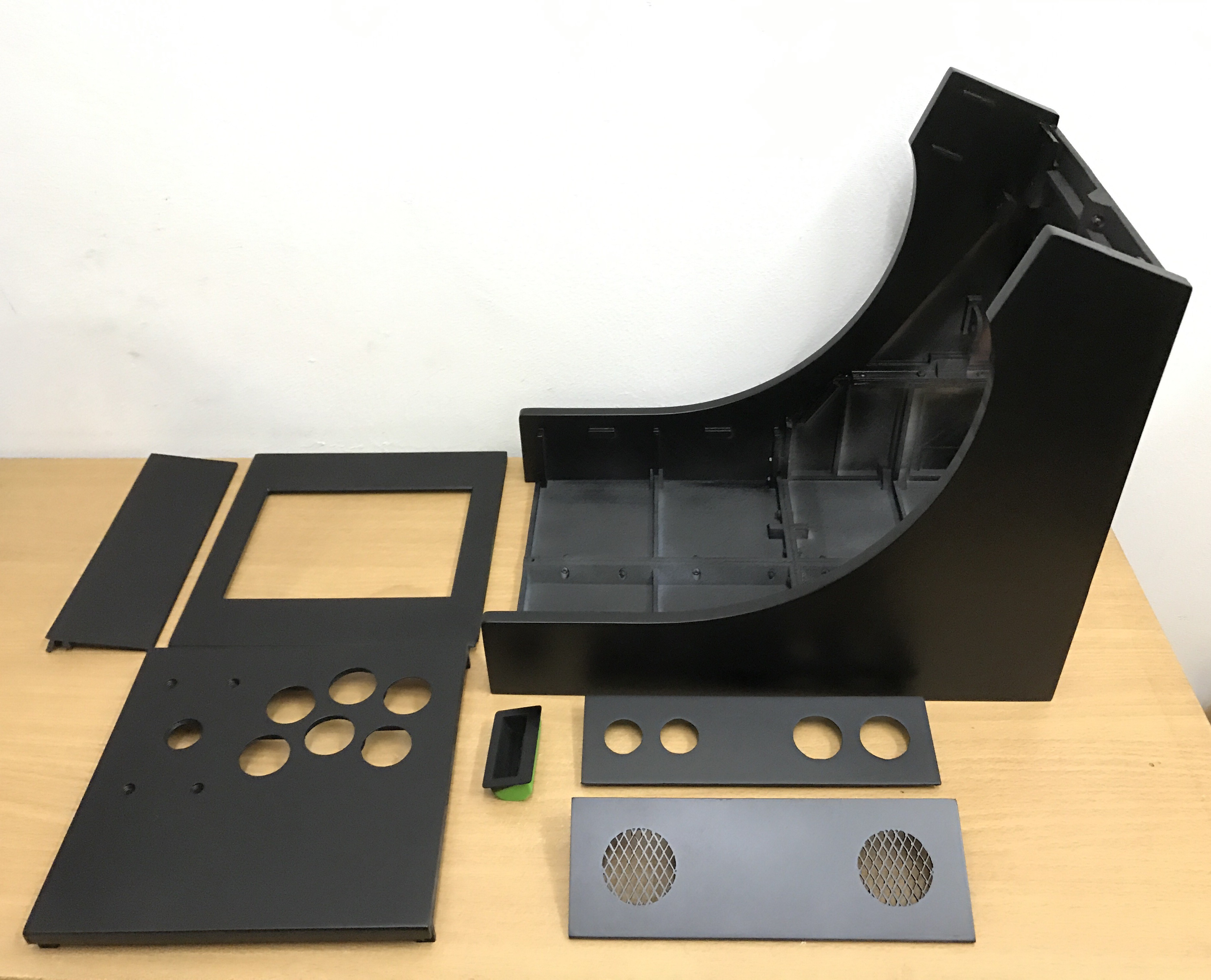
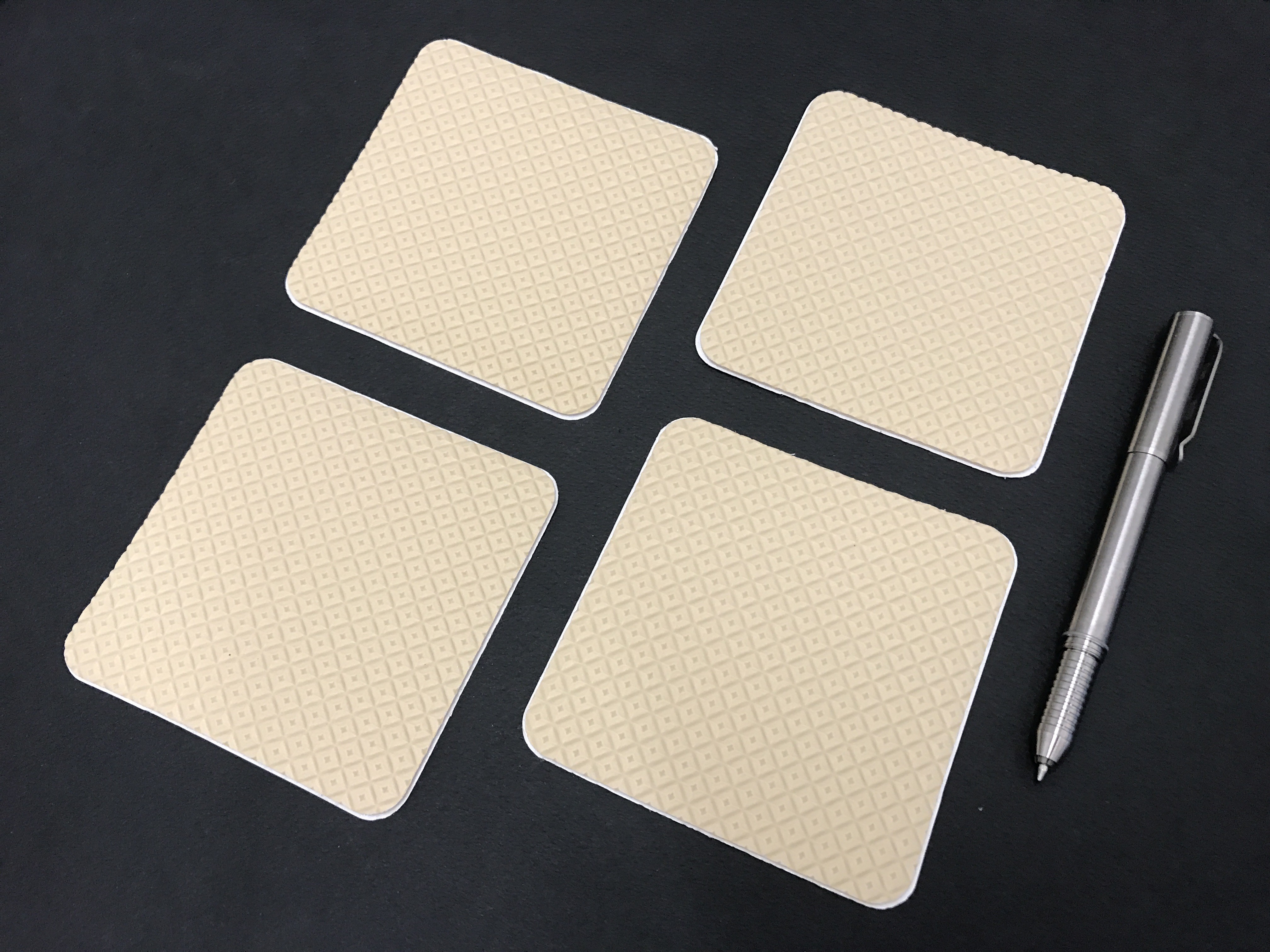
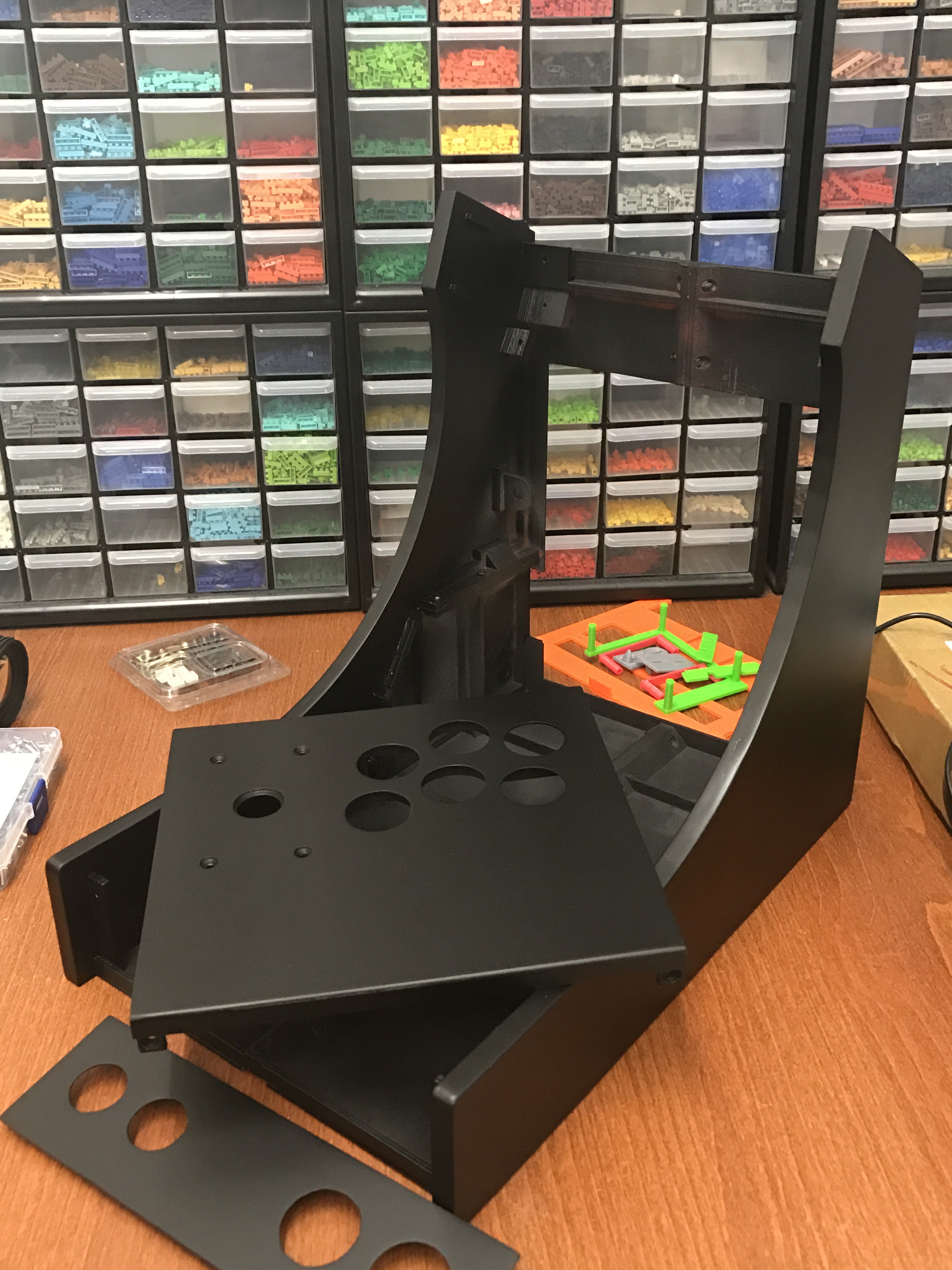
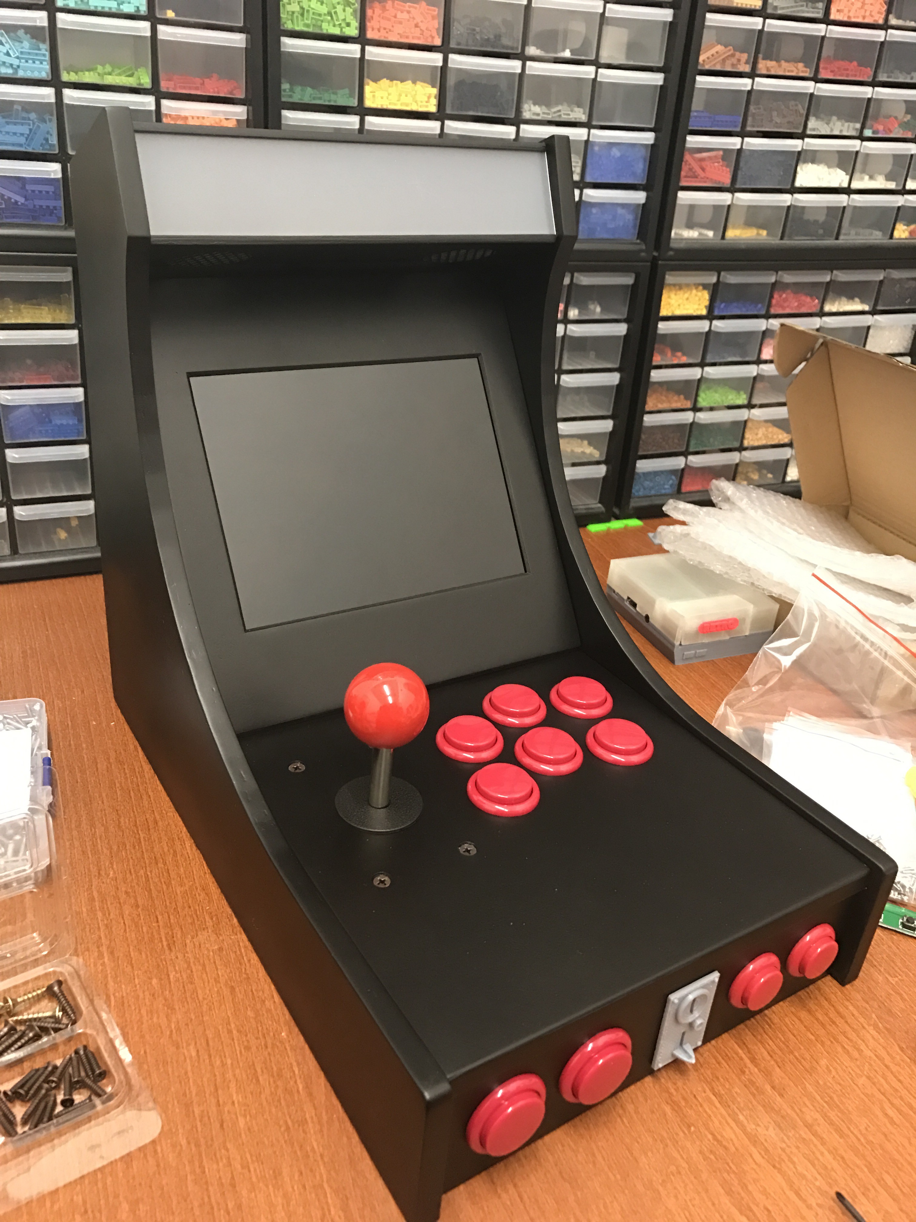
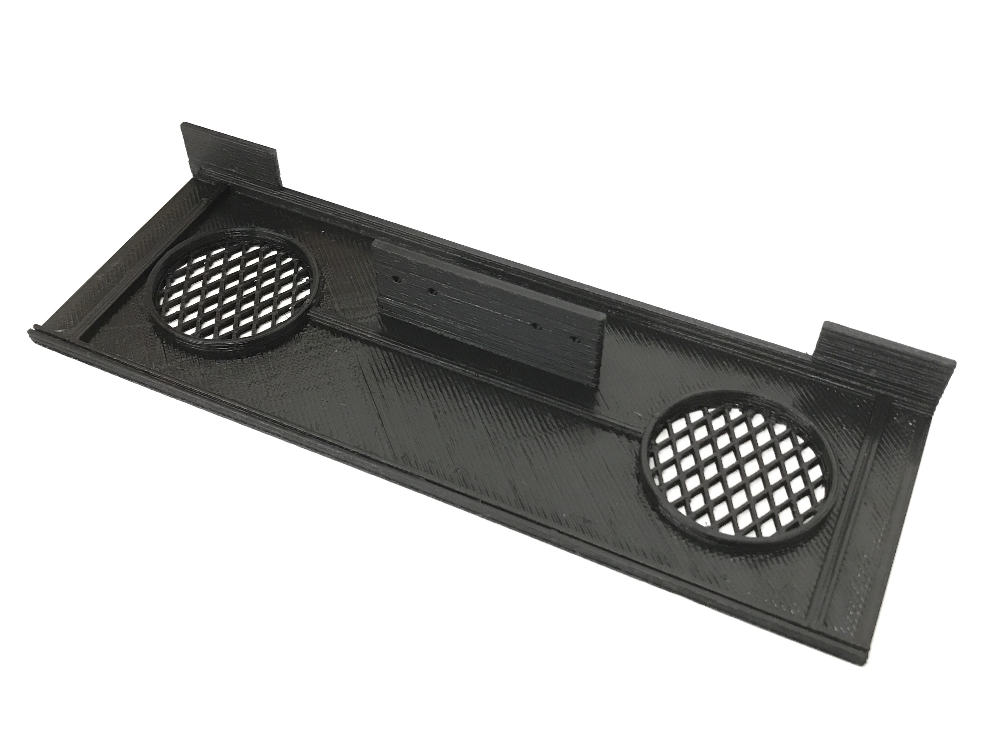
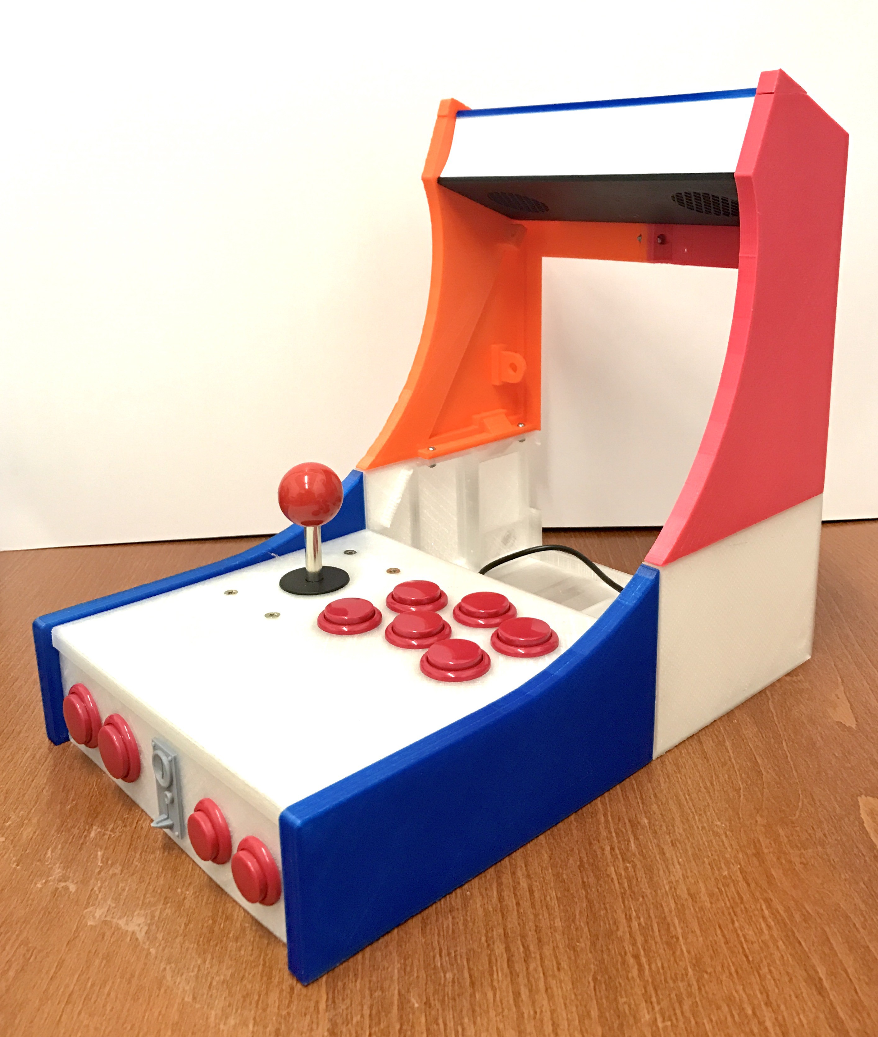
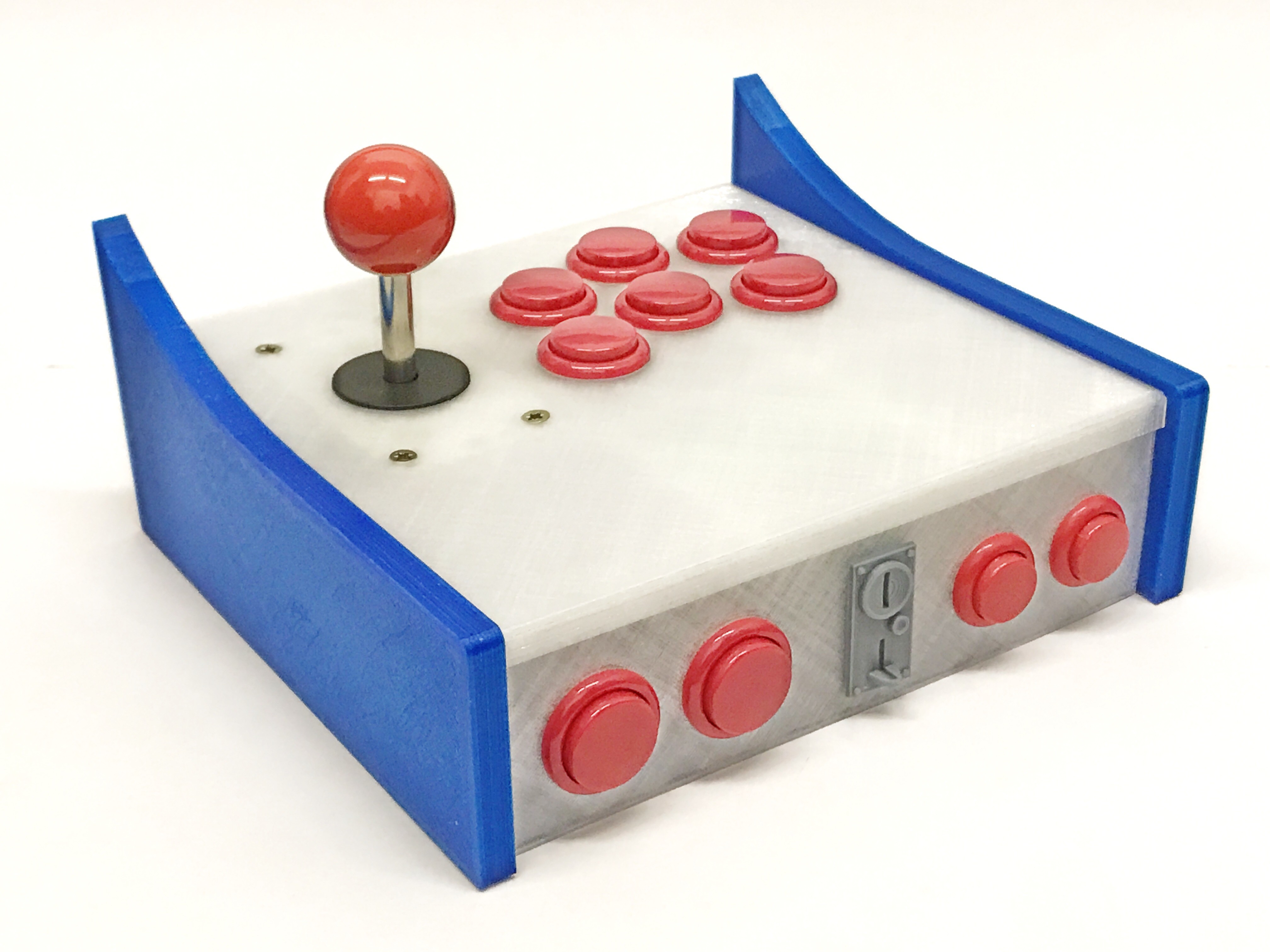
So, that's pretty much all the parts printed.
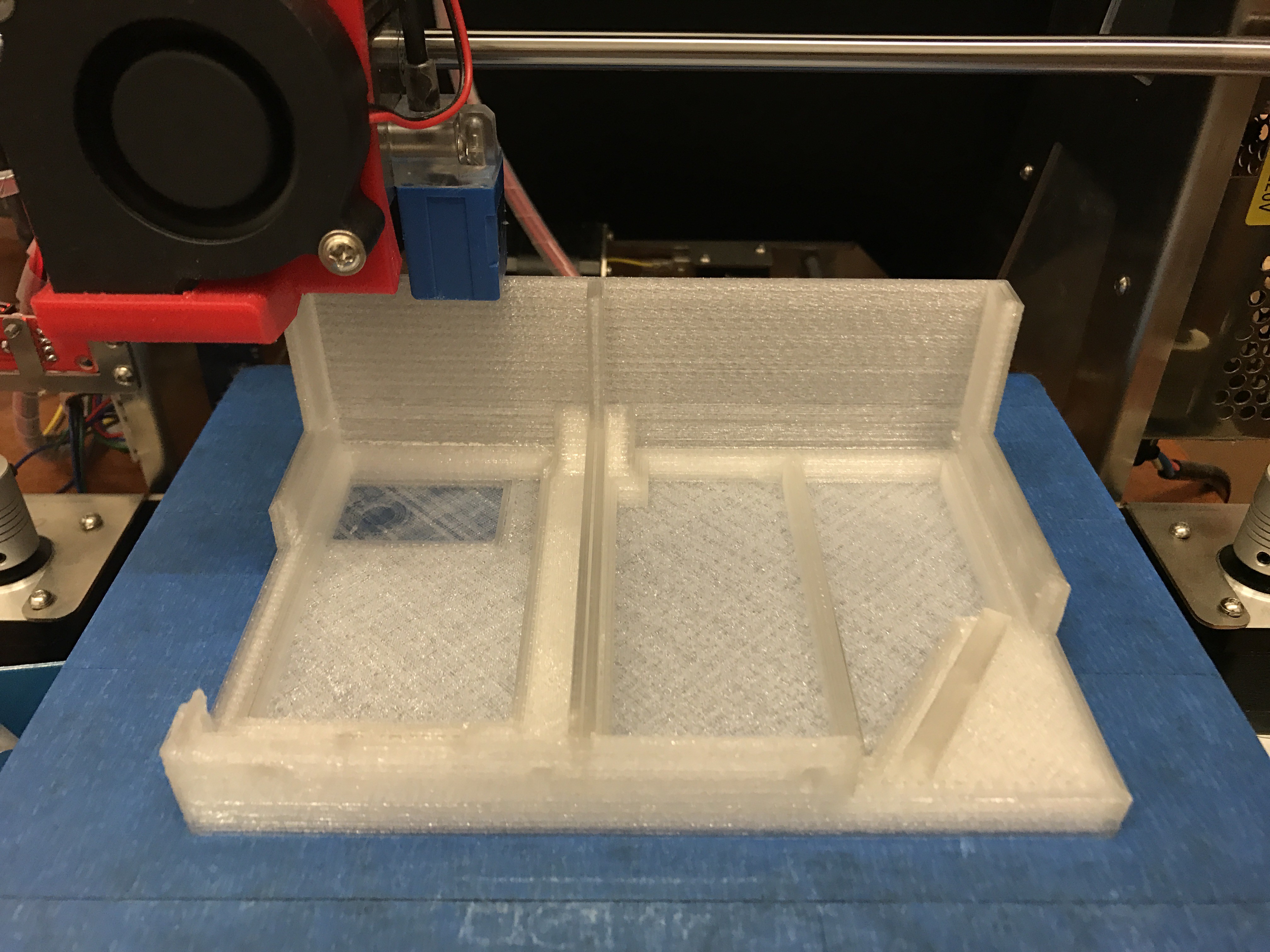
  • The Back of the Machine

    Christopher Tan03/08/2017 at 05:32 0 comments

    With the front portion completed, we move on to the back portion of the machine.

    Here it is printing the bottom back part.

    And here's what it looks like completed:

    Next, we move on to the top of the back portion.

    This is what it looks like attached.

    The part below the marquee that will hold two 4cm speakers and LEDs.

    The part above the marquee has been printed as well.

    Now it's starting to look like an arcade machine. Please ignore all the different coloured parts, I was just trying to use up all the filaments I currently have.

  • The Controller

    Christopher Tan03/01/2017 at 11:57 0 comments

    I wanted a real arcade joystick + buttons, so I ordered these online and they do feel really good.

    Here's where it fits into. I made sure to add more support structures in the design to ensure it would be rigid and not flex when in use.

    This is what it looks like, complete with the coin slot and front button panel. Here, I am just testing the controller on my Android tablet first.

    Now to print the bottom parts under the controller.


    Here's the front half of my arcade machine completed!

View all 8 project logs

  • 1
    Step 1

    3D print all the pieces. I used PLA for stiffness. All my 3D models were designed to be printed without the need for any support structures. You will need a 3D printer with a minimum print volume of 220mm x 220mm x 120mm in order to print these files.

    I should note that I actually designed and printed these parts *before* receiving the actual parts like the LCD screen, controller, speaker, amplifier etc. 3D printing takes quite a lot of time and I didn't want to wait till everything I ordered has arrived in the mail before I started printing. So, some of the parts were designed with some flexibility in terms of how it would be laid out. Also, this was a learning process for me as I am still relatively new to 3D printing, so some parts have gone through many changes as I experimented with the design. I believe all the files I uploaded should be correct, but in case there are any mistakes, do let me know.

    Please understand that I am sharing these files AS IS. You do need to have a decent knowledge of 3D printing, Raspberry Pi, soldering, etc. in order to put it all together. Any information that I did not include here, you will be able to Google it.

    Here are reference photos to give you a better idea of how all the pieces fit together.

    Here are exploded views to give you a general overview of where everything is positioned.

    And here are the completely assembled views.

    Most of the main pieces are held together using nuts and bolts, or screws. You will need M3 bolts of various lengths (probably 10mm - 16mm) and some screws. I am afraid I lost the specs of the screw I used, but it's about 10mm long and 2.5mm diameter. These were use for the marquee pieces.

    I sprayed primer putty and sanded it down to a smooth finish before spraying matte black paint for the final finish. You want to make sure you sand the top edges of "Body - Front Left" and "Body - Front Right" so that they are nice and smooth, cause otherwise, when you rest your hands on them, the sharp edges will get irritating quite quickly.

    In order to make it look like a commercial quality product, I did a lot of research into the designs of the artwork for old arcade machines. I took inspiration from them to create my own artwork for my arcade machine and had it commercially printed on vinyl stickers.

    Connecting Everything Together

    • The controller's USB connector will plug into the Raspberry Pi's USB socket.
    • The power connecter for the display will plug into the Raspberry Pi's USB socket.
    • The HDMI out on the Raspberry Pi needs to be connected to the HDMI input on the display controller board.
    • The speaker needs to be soldered to the amplifier circuit, and the amplfier circuit's power input needs to the connected to the Raspberry Pi's GPIO pin 4 & 6 for the 5V power supply. You also need to solder an earphone jack connector to the amplifier circuit and plug that into the Raspberry Pi's audio socket.
    • Solder together the LEDs and wire it to a USB connector. Plug it into the Raspberry Pi's USB socket.

    So, everything is powered directly from the Raspberry Pi. The only cable going into the arcade machine is the Raspberry Pi's power supply cable.


    Software Setup

    You will need to get RetroPie setup and configured. For that, please check out RetroPie's website (https://retropie.org.uk) and Google for anything you need. All the resources you need are out there!

  • 2
    Step 2

    Display Issue Fix

    The first time you try to power up the full setup, make sure to power the display from a SEPARATE USB power supply FIRST, before turning on your RPi. The display needs to be active first, otherwise your RPi would not use HDMI for display. Also, connect a keyboard to your RPi.

    After powering up your Raspberry Pi, let it boot up all the way until Emulation Station/Attract Mode comes up (depending on your setup). Exit to terminal.

    Open the Raspberry Pi configuration file for editing with this command:

    sudo nano /boot/config.txt

    Use arrows to get to the end of the file and add these 3 lines:

    #Always force HDMI output and enable HDMI sound

    hdmi_force_hotplug=1

    hdmi_drive=2

    Save the changes by pressing CTRL + O and ENTER

    Exit the editor by pressing CTRL + X

    Now you can turn everything off, reconnect your display's power supply to RPi's USB socket. Now when you turn it on, your RPi will default to HDMI output even though the screen is powering up later than your RPi.

View all instructions

Enjoy this project?

Share

Discussions

pkappetein wrote 07/04/2022 at 18:25 point

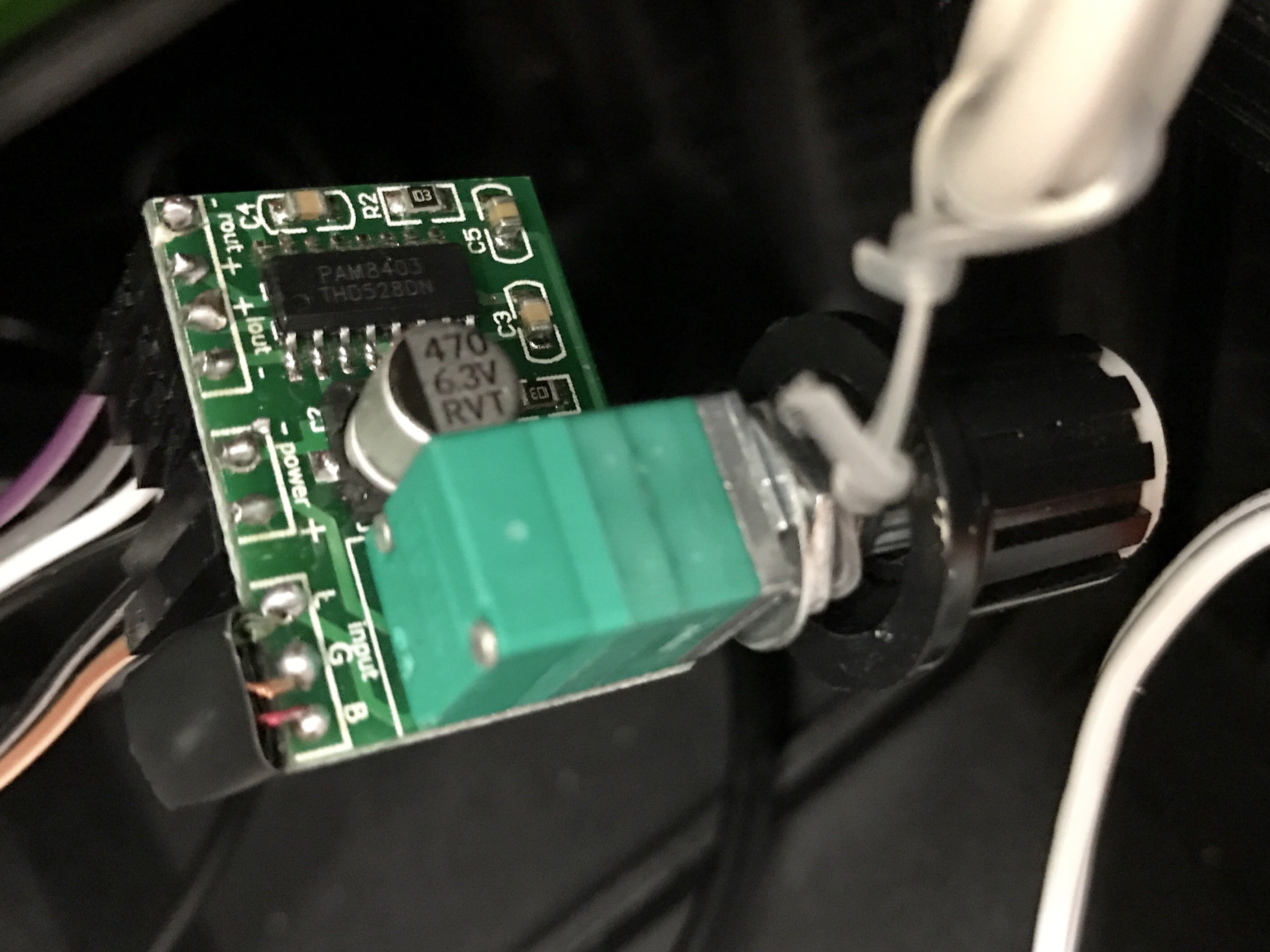
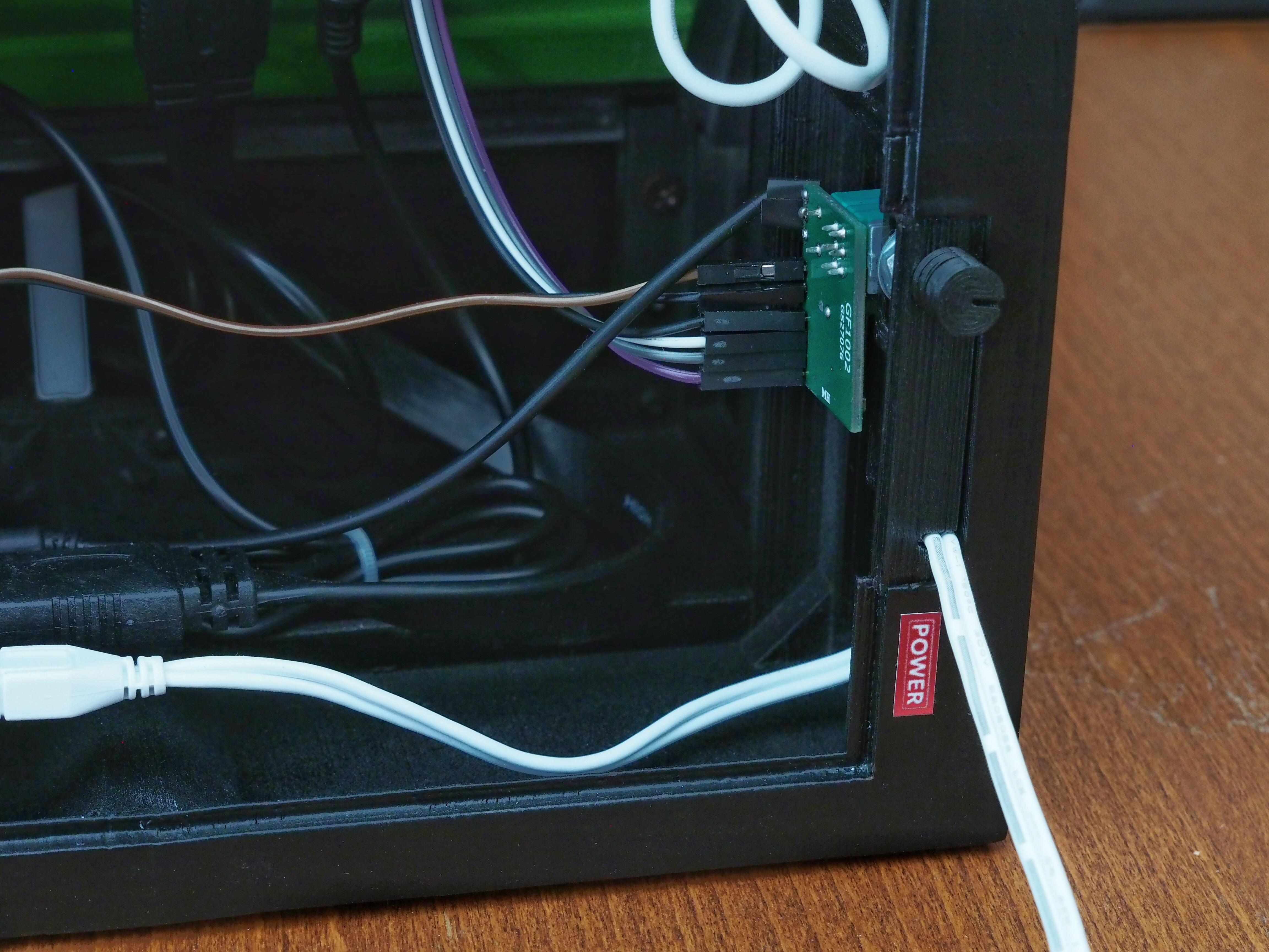
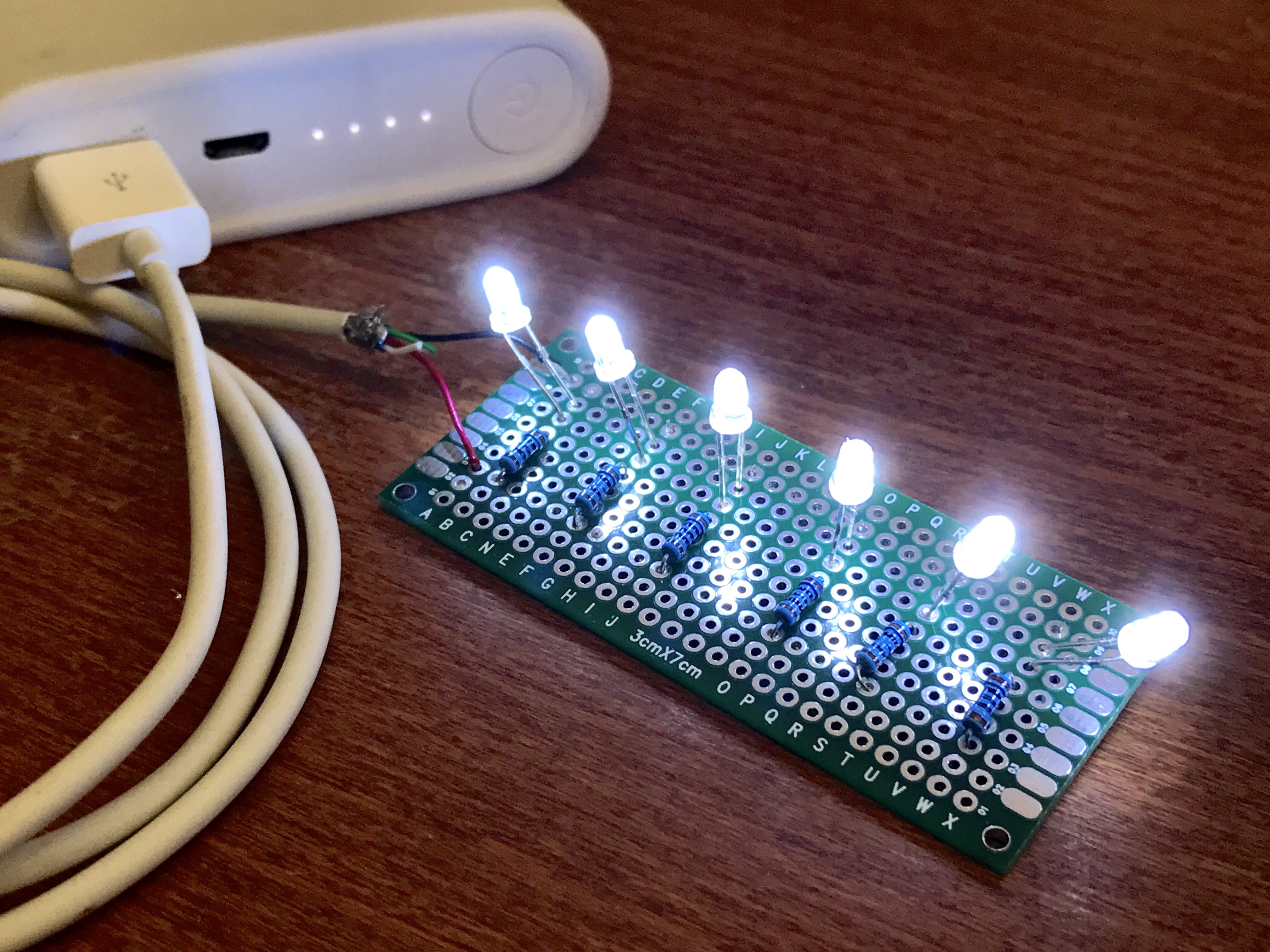
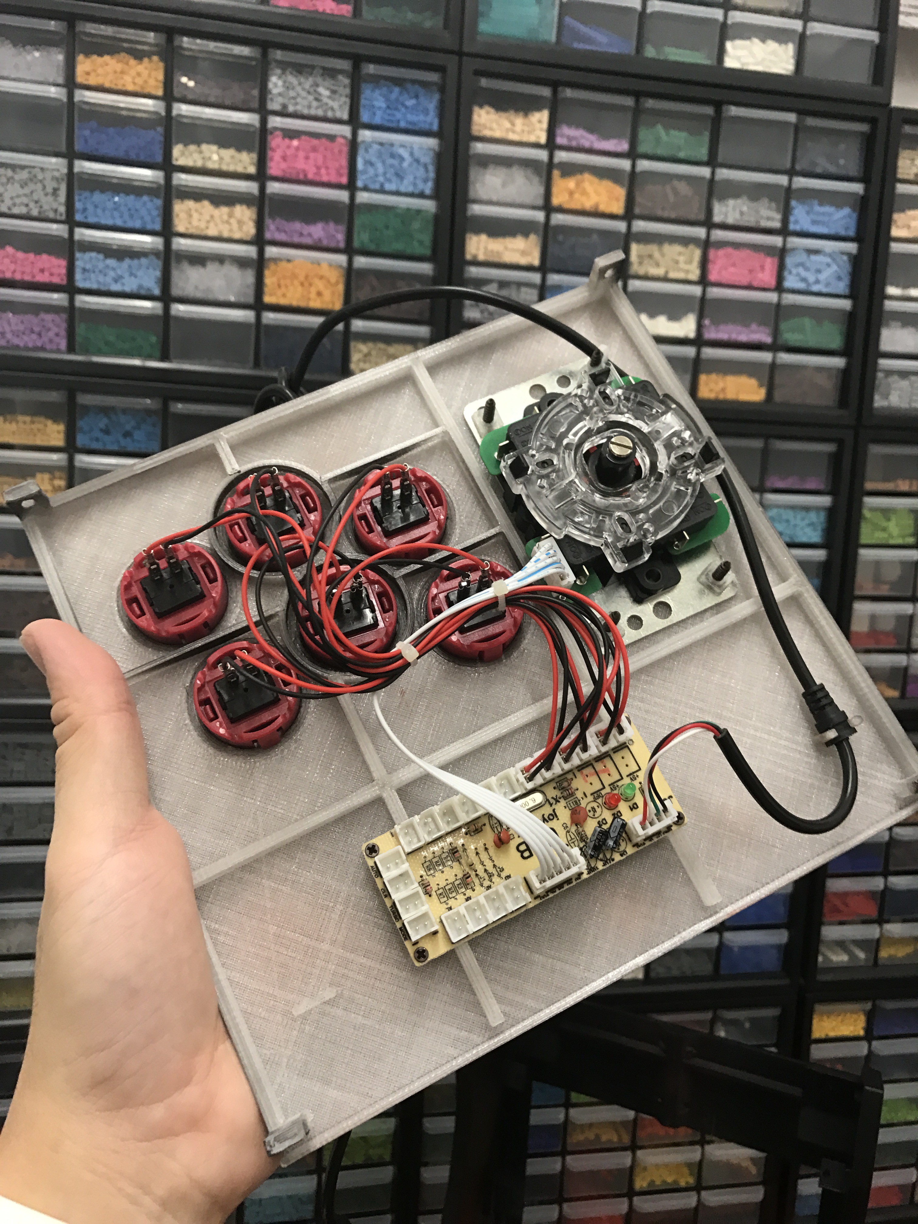
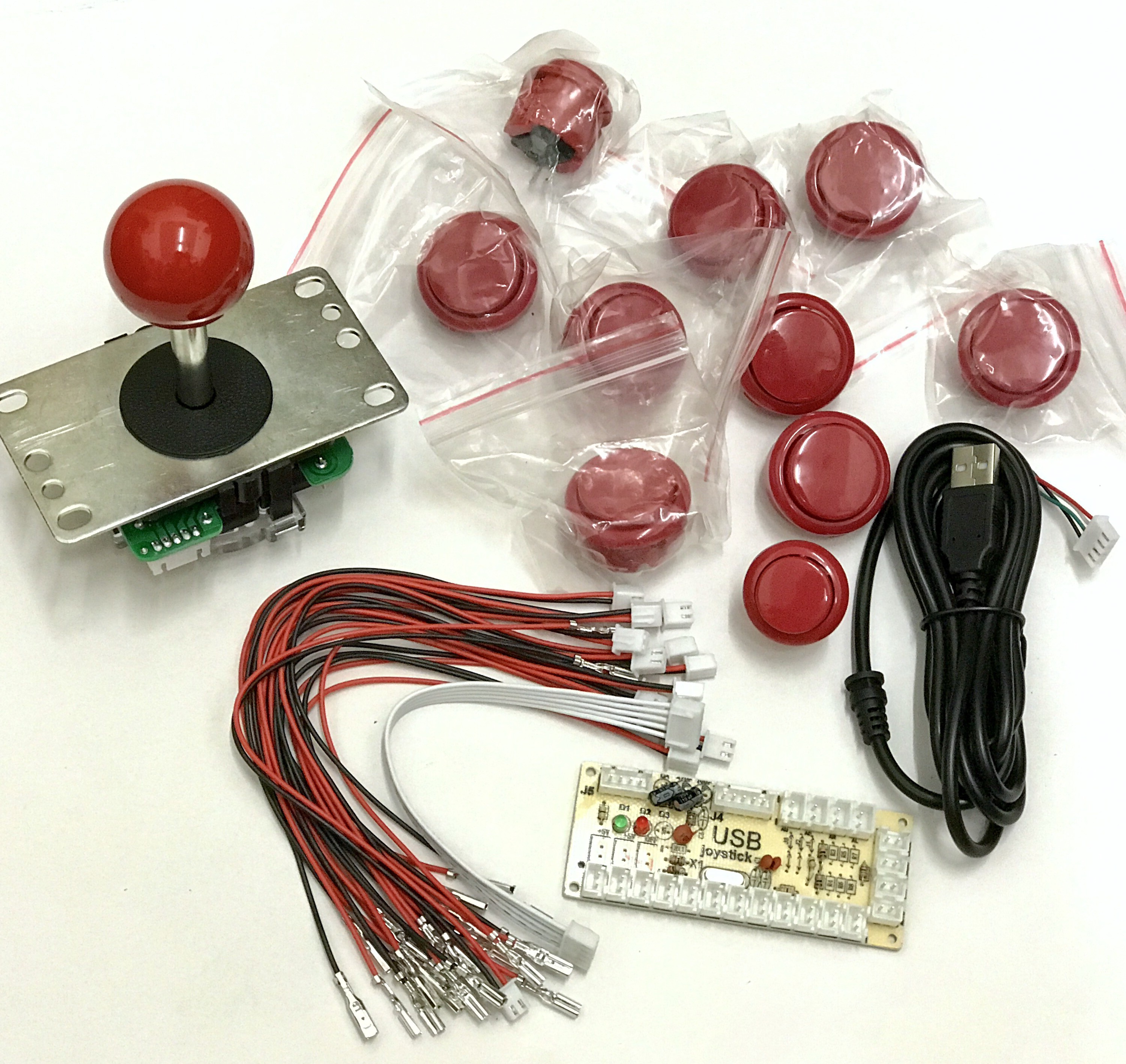
How do I hook up all the wires etc.  I can't find anything on how to connect everything.

Thank you

  Are you sure? yes | no

Dairo Joel wrote 11/22/2020 at 22:13 point

Es necesario tener conocimientos básicos de electrónica o desde cero se puede?

  Are you sure? yes | no

jdlopez wrote 11/13/2020 at 18:21 point

Hey Chris. Great project, my son and I are working on one together. :) I know i'm late to the party on this, but I got the display in. Your instructions say you're using USB to power the display controller. Did you make your own cable? I'm looking at the board and it's calls out for a 12V power supply. Doesn't USB only provide 5VDC?

  Are you sure? yes | no

Craig wrote 06/09/2020 at 12:17 point

How do I mount the front panel and controller panel?  I can't figure out how to manage to get all of the pieces screwed together.   The screws that hold the controller panel on are hidden by the front panel, however, I can't figure out how to get the front panel under the controller panel edge and also get the screws in place?

  Are you sure? yes | no

teamminers56 wrote 03/03/2019 at 16:02 point

Can you add a real coin acceptor?

  Are you sure? yes | no

james.demacek wrote 01/17/2019 at 14:47 point

Is there any chance you could provide the "shape" file for the panels so we can design our own vinyl decals?

  Are you sure? yes | no

Dave wrote 07/07/2018 at 21:33 point

Christopher - Is your original artwork available? I'm looking at eliminating three buttons and putting a spinner in their place, and I'm also putting a track ball just above the coin slot. (Time to play Tempest, Crystal Castles, and so many other games the way they should be played!)

  Are you sure? yes | no

Dave wrote 07/07/2018 at 12:46 point

I just ordered the components for this, and it'll be the first thing I make with my new 3D printer!

Does anyone have suggestions for places in the US where I can get the stickers printed?

  Are you sure? yes | no

daviddnet wrote 01/20/2018 at 17:43 point

awesome buddy you rocks. I want to build my own, but for two players.

  Are you sure? yes | no

Jonathan Kimrey wrote 01/11/2018 at 10:08 point

Is it possible to print everything using a Maker Select Plus (200 x 200 x 180)?

  Are you sure? yes | no

Ron Lawson wrote 08/18/2017 at 01:52 point

Great project! I'm currently building this and am very new to electronics. You don't happen to have a picture of the back side of the prototype board used for the LED marquee do you? I tried wiring it up with my limited knowledge and got no light from the Raspberry Pi USB. Thank you. 

  Are you sure? yes | no

Erik Dominick wrote 07/06/2017 at 23:29 point

In your opinion do you think it would be an easy mod to the design to fit a 9.7" ipad screen in this cabinet?

  Are you sure? yes | no

Paul Baim wrote 04/04/2017 at 21:46 point

Sweet. What format are the original 3D files in? The STLs can be modified but the originals could be easier. Also, will you provide the sticker artwork files or at least info on who you sourced the stickers from?

Thanks!

  Are you sure? yes | no

Christopher Tan wrote 04/20/2017 at 16:03 point

I created them in TinkerCAD and it allows export to STL or OBJ. I have uploaded the sticker artwork, so just grab it from the files section :)

  Are you sure? yes | no

jean-paul wrote 03/25/2020 at 10:59 point

A late reply but is it possible that you upload the Tinkercad-design files? I want to make this build but my 3Dprinter has a smaller buildplate so i have to resize the shapes to fit without losing the correct measurements for the buttons etc. ANd use a smaller screen is neccesary..

  Are you sure? yes | no

Paul Baim wrote 03/25/2017 at 18:07 point

Super build! Please put the design files on line!

  Are you sure? yes | no

Christopher Tan wrote 04/04/2017 at 05:13 point

I've just uploaded all the 3D files and added links on where I got the parts =) ... Will put up more instructions shortly.

  Are you sure? yes | no

Similar Projects

Does this project spark your interest?

Become a member to follow this project and never miss any updates