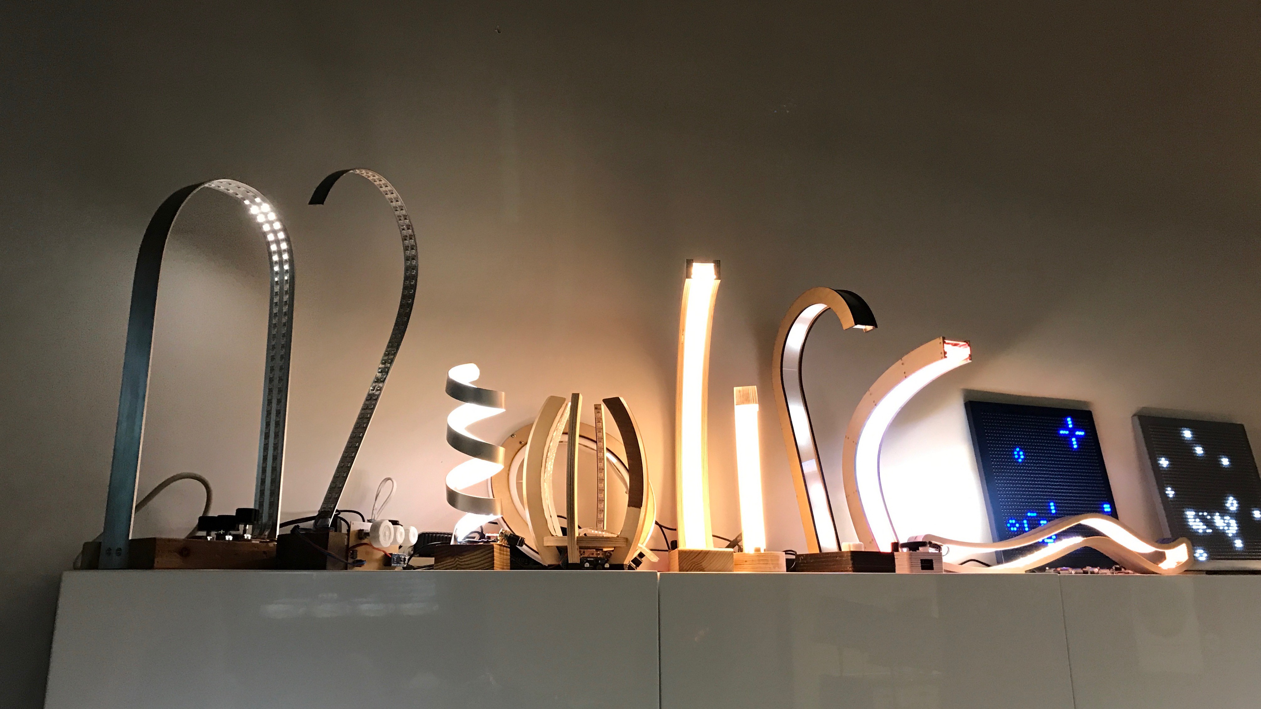
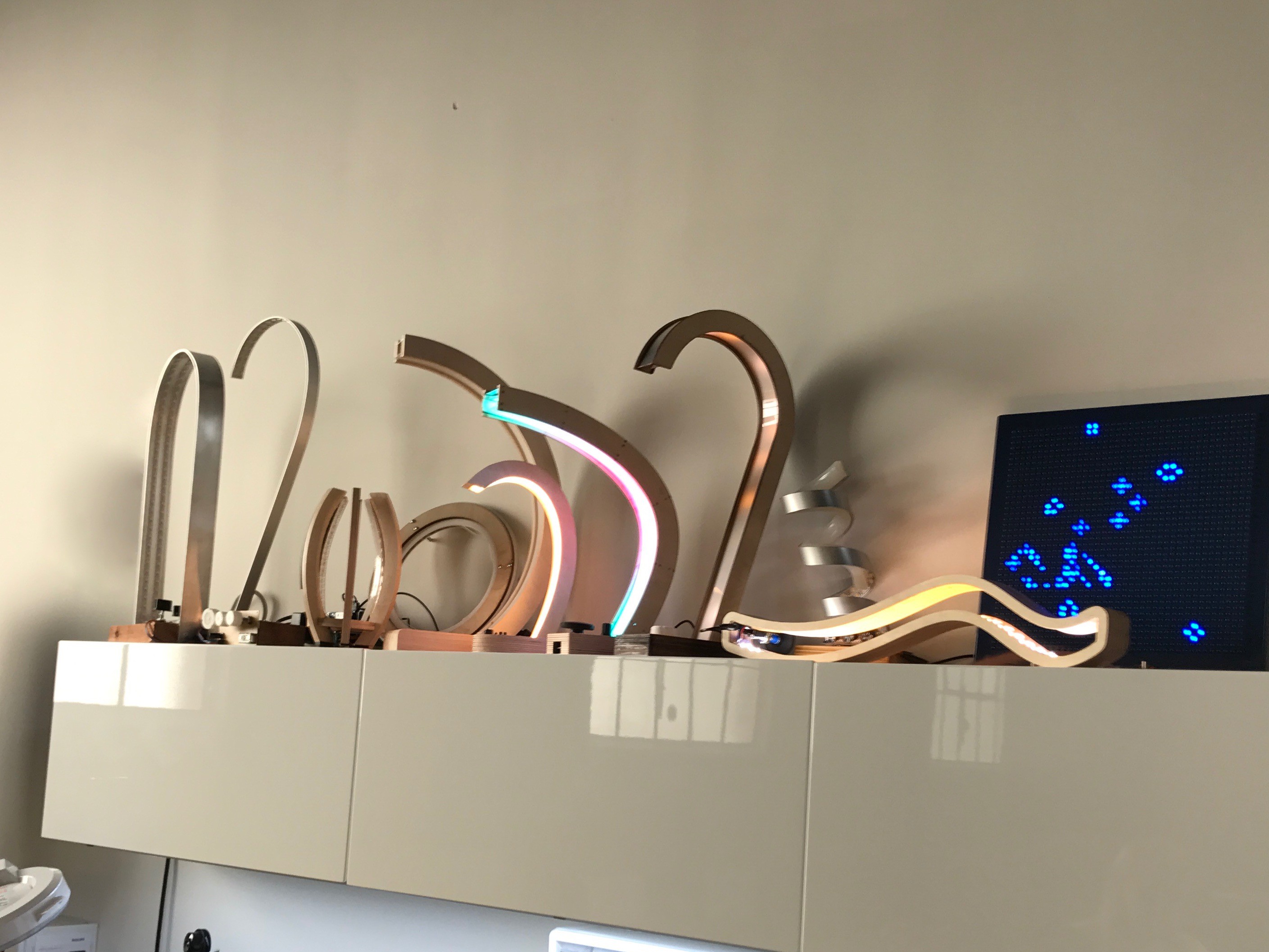
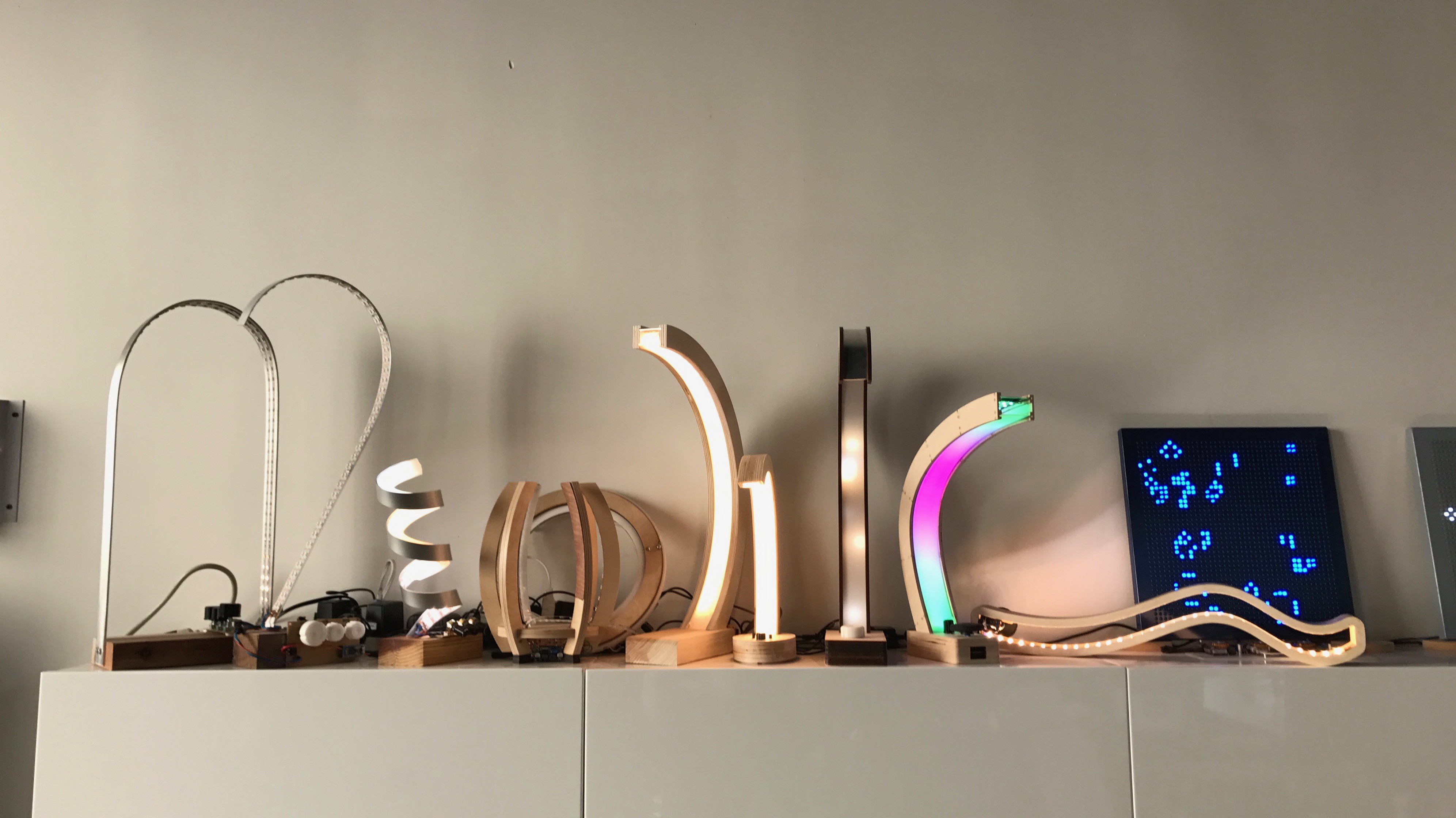
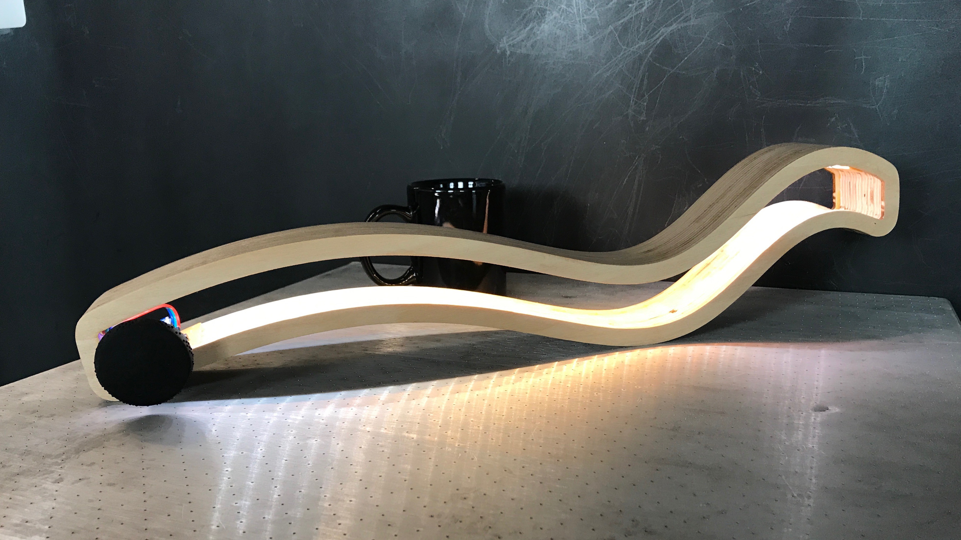
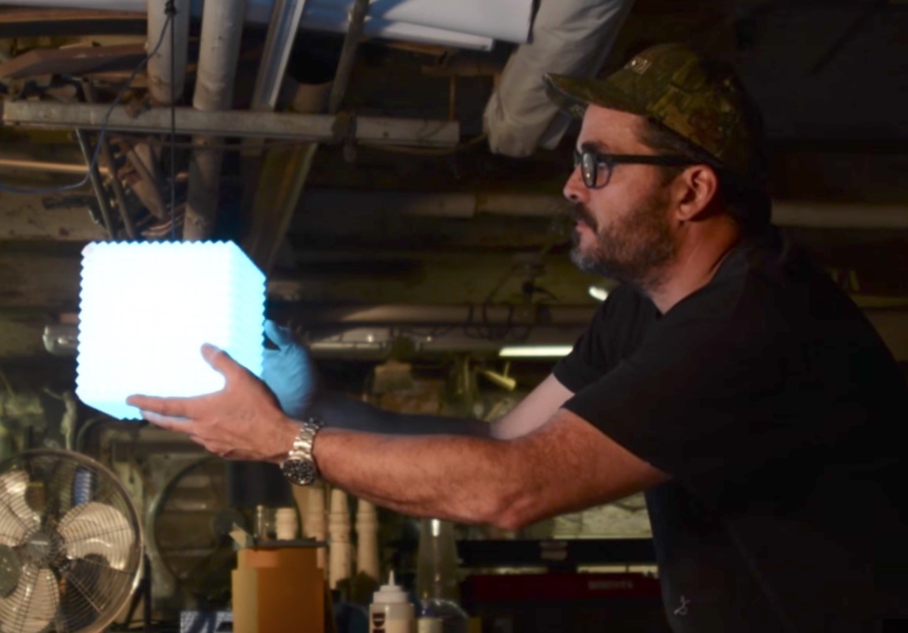
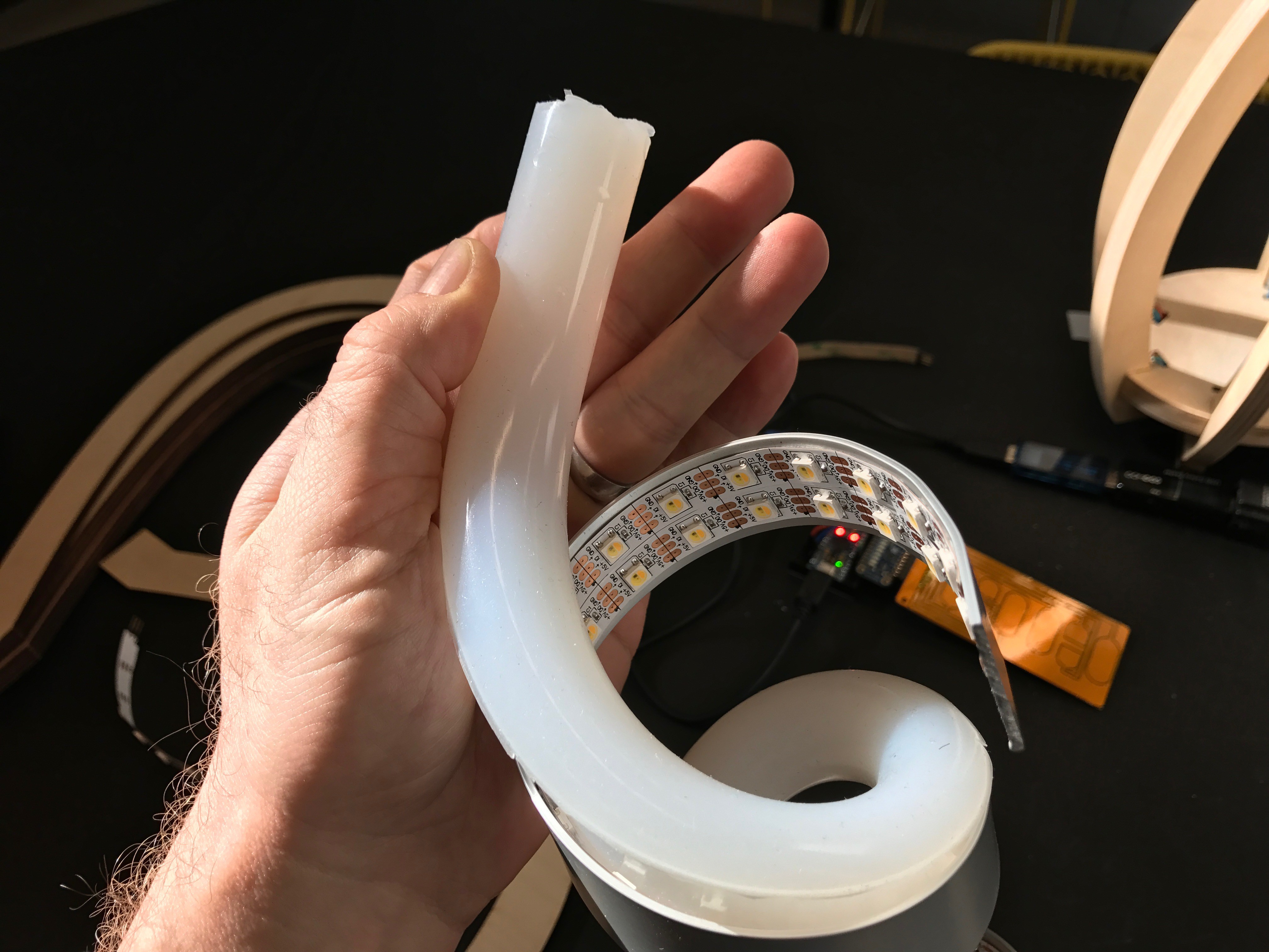
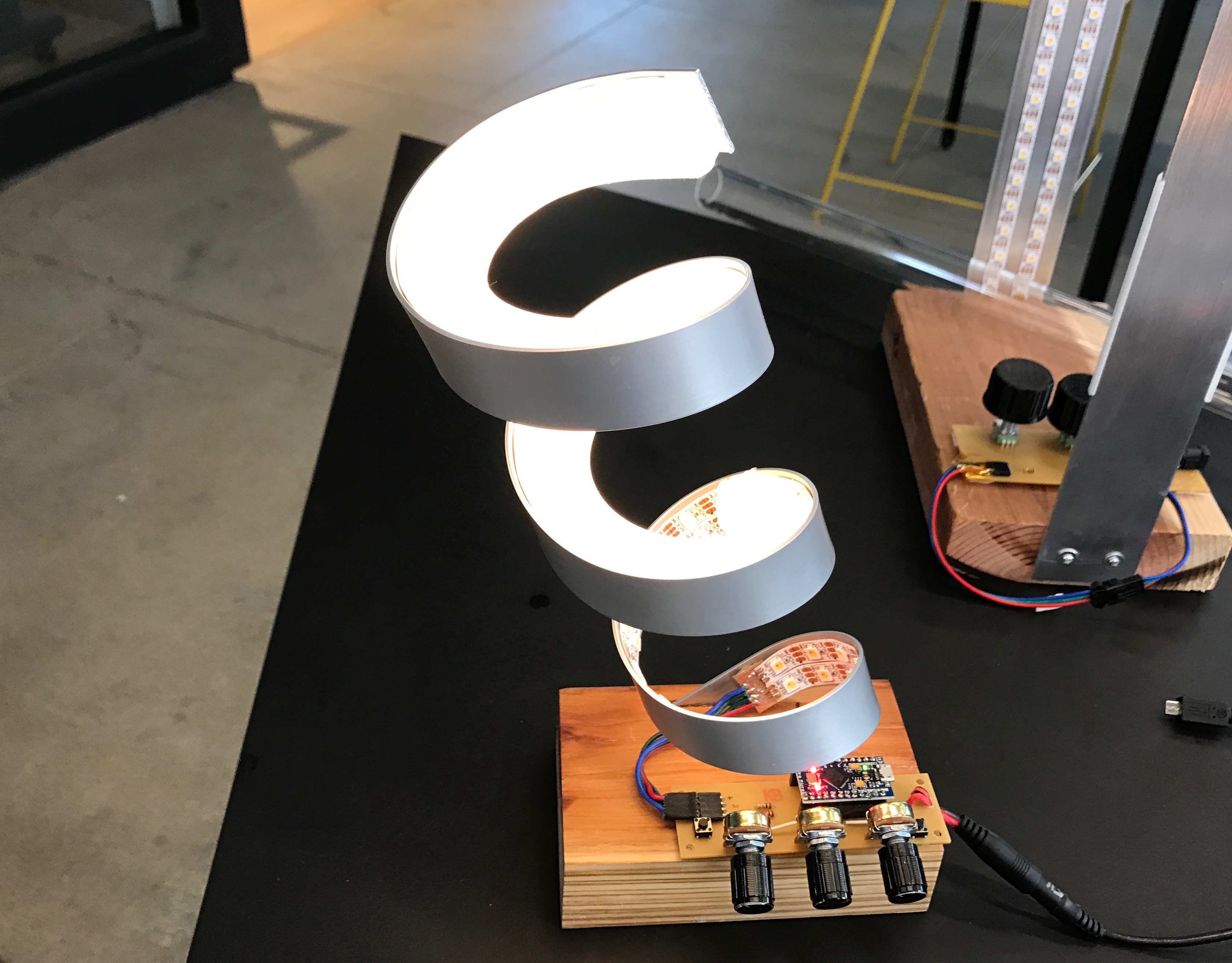
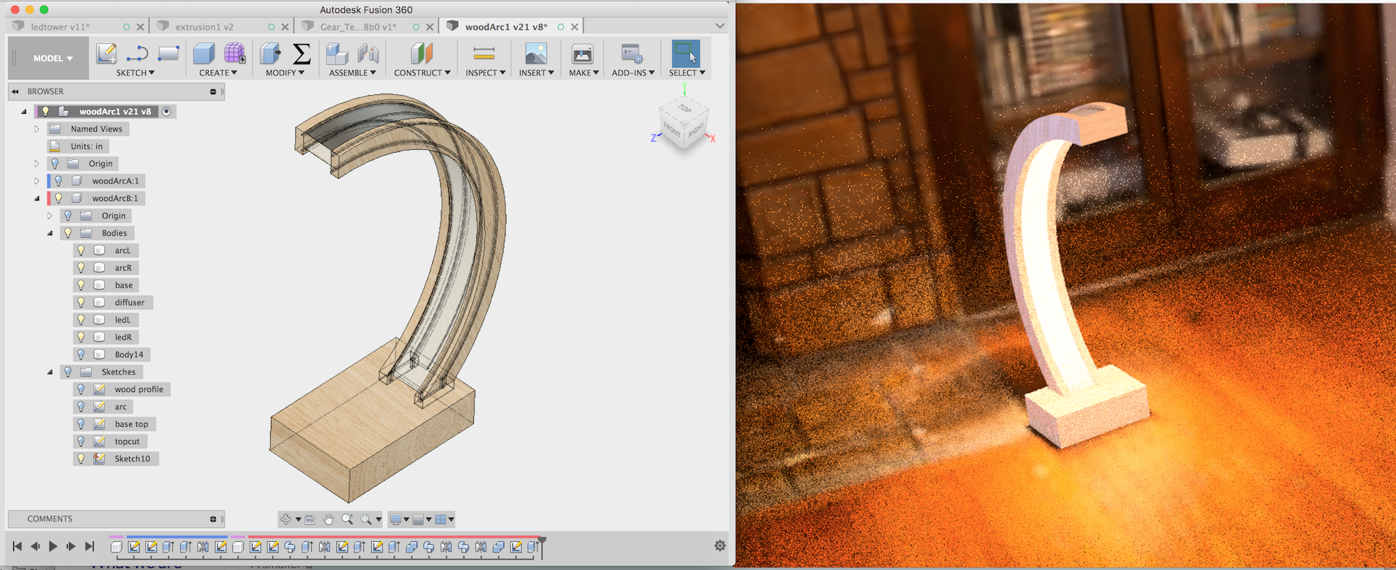
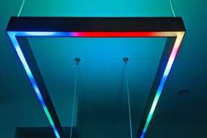
 todbot
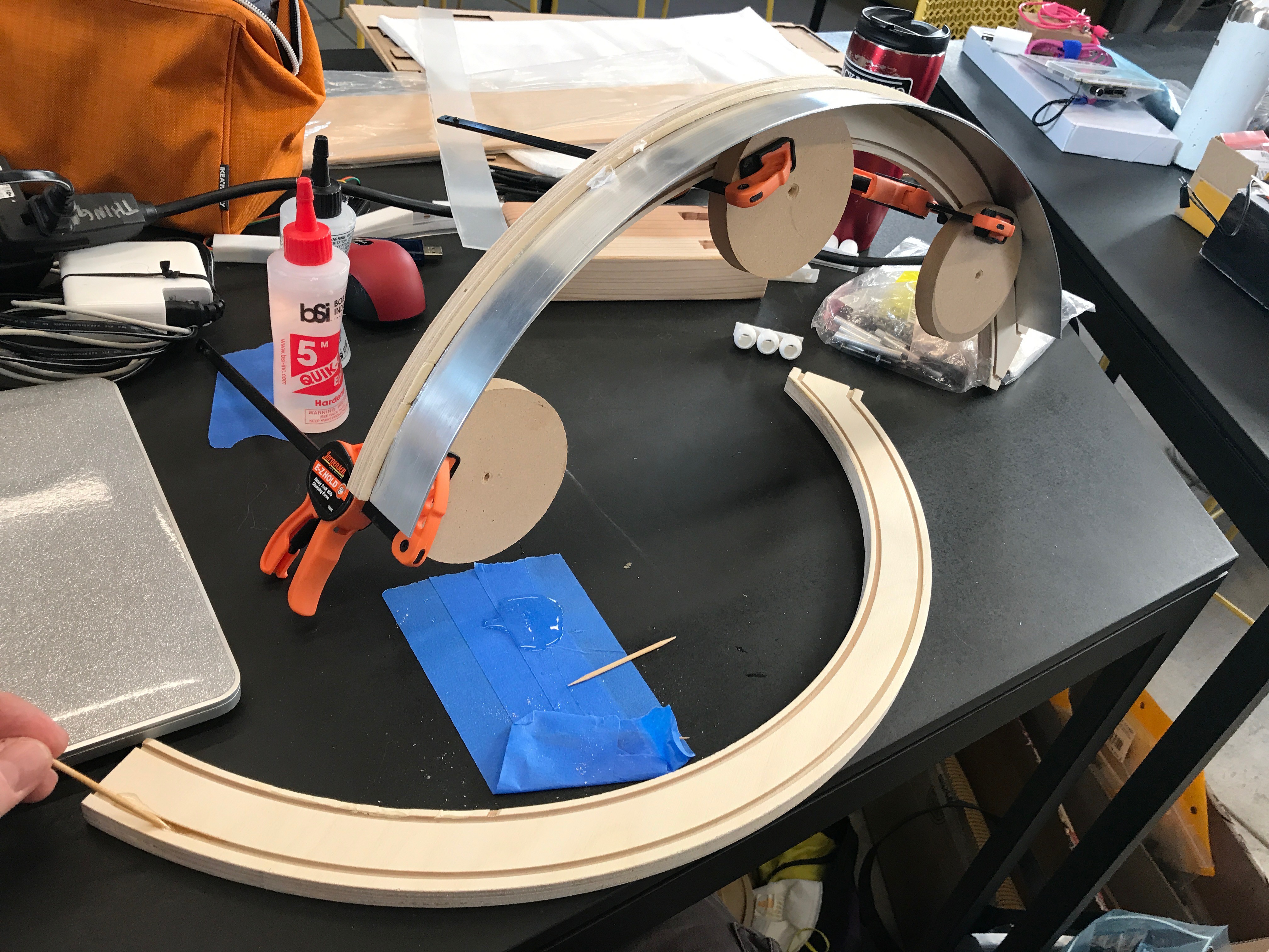
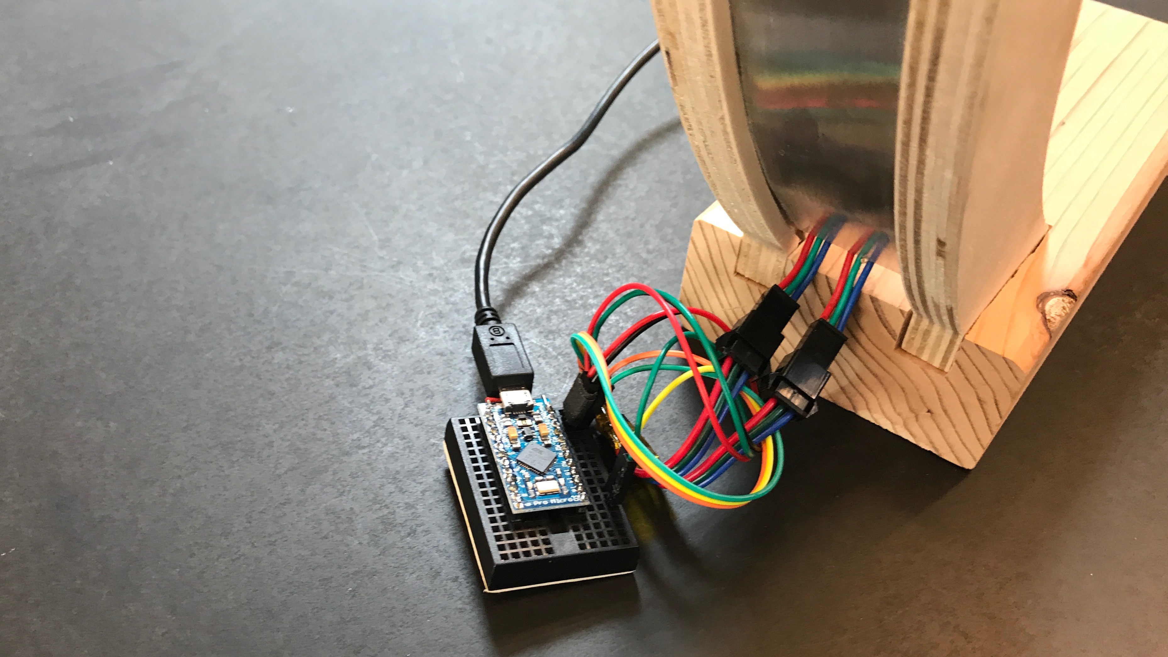
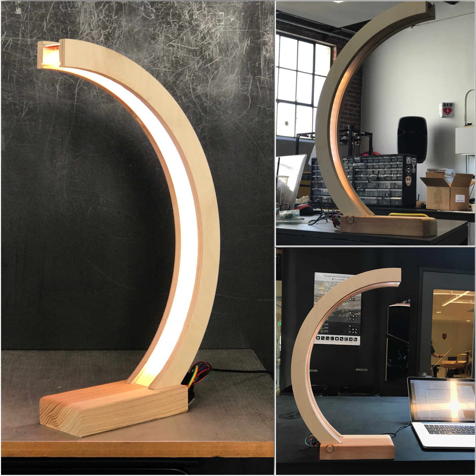
Part of the SupplyFrame Design Lab residency #0x02
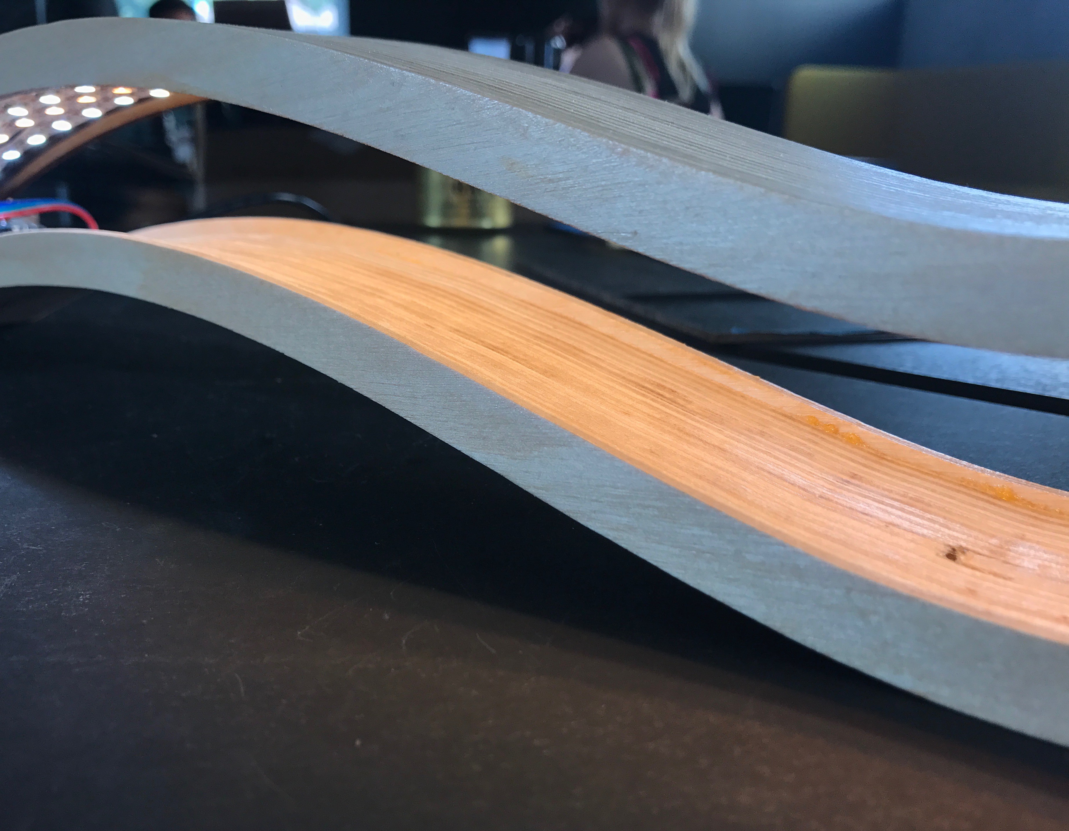
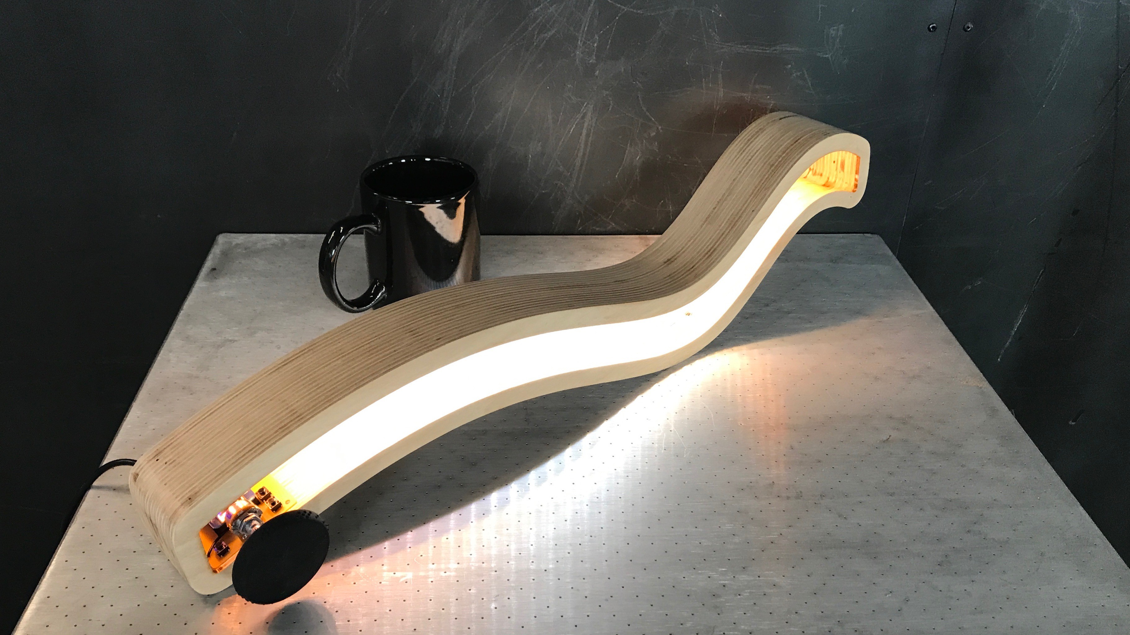
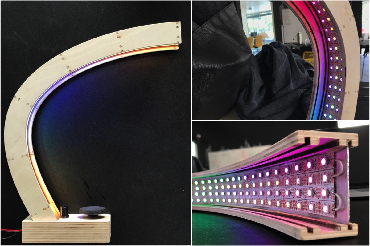
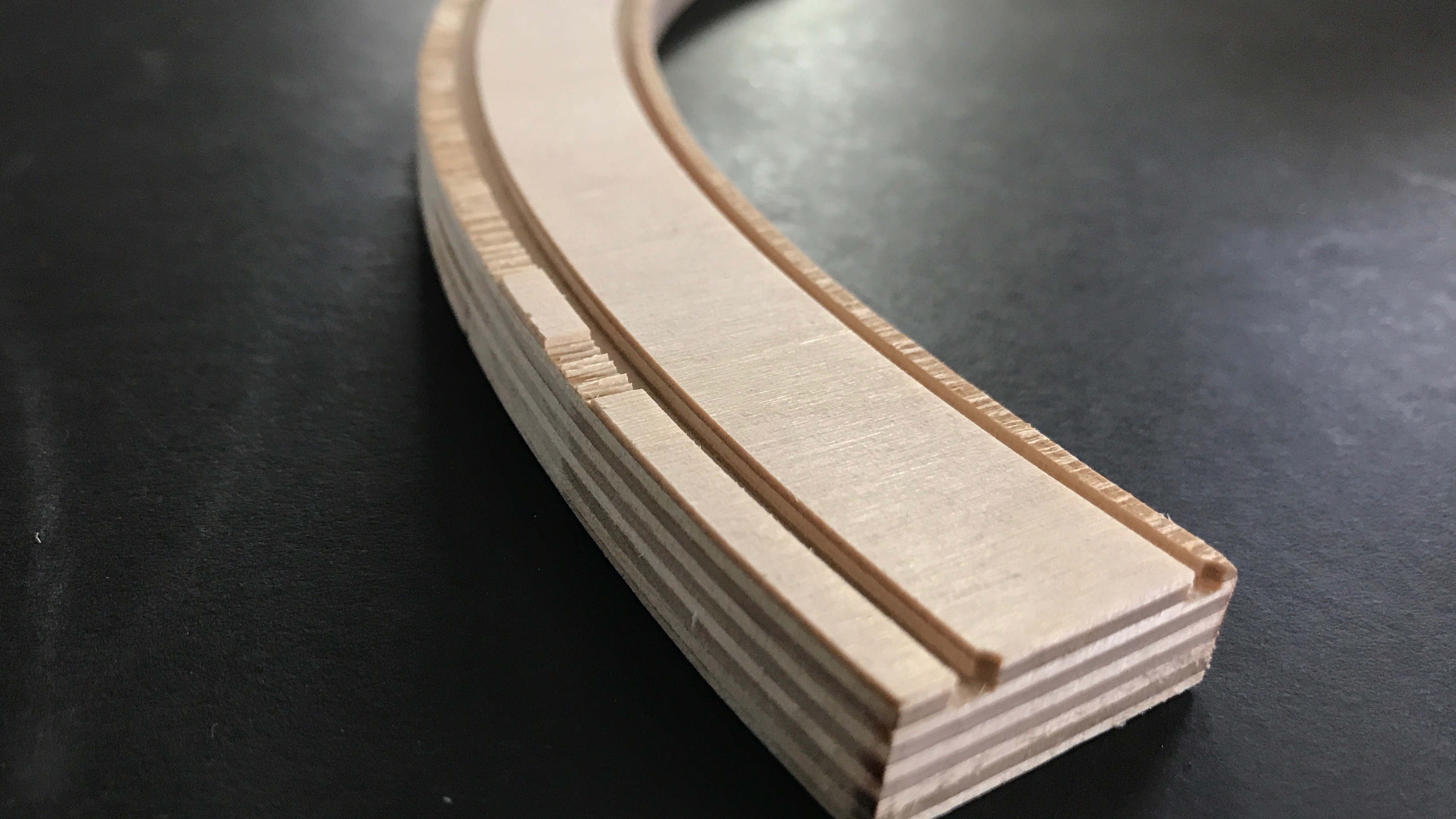
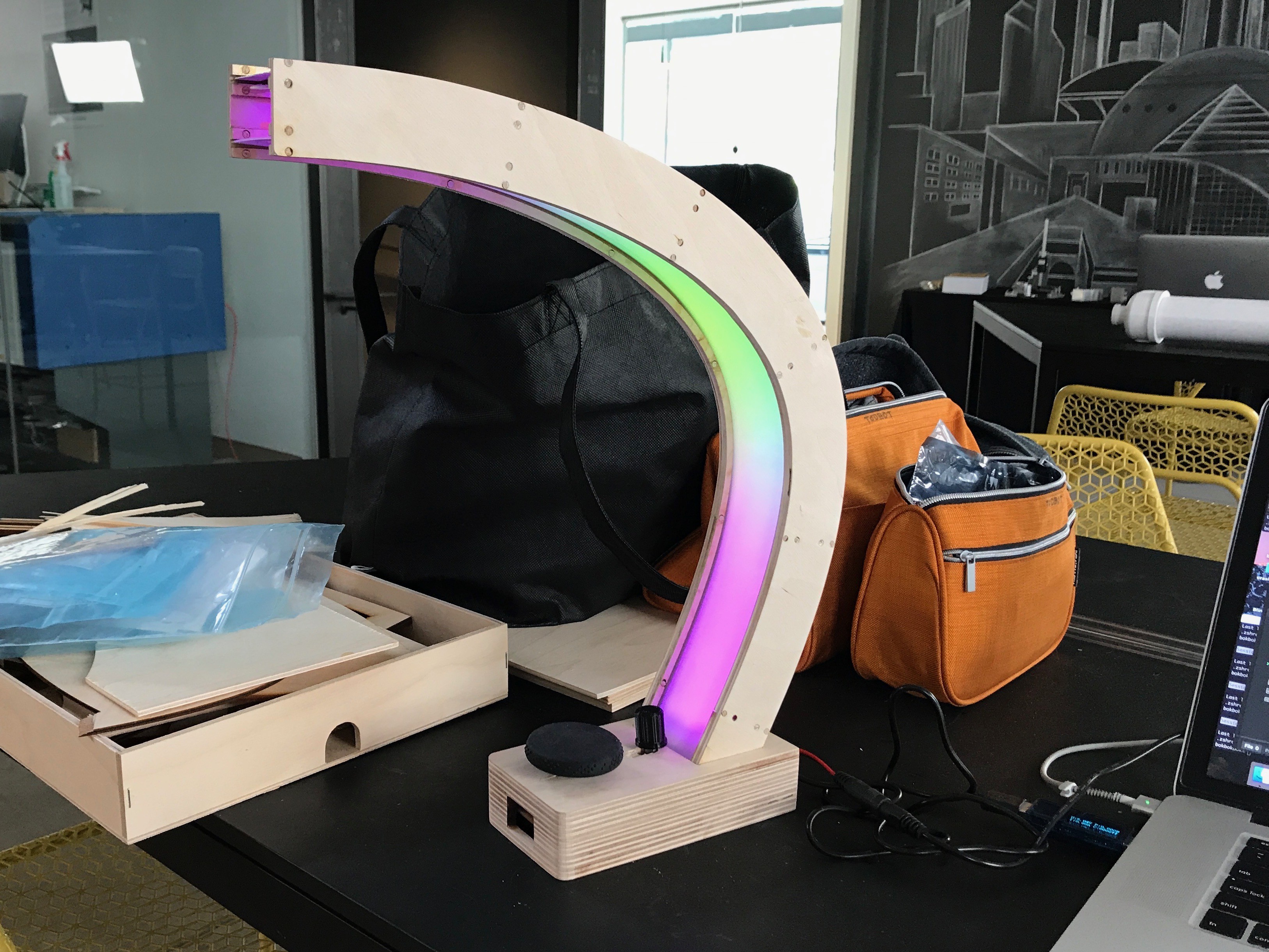
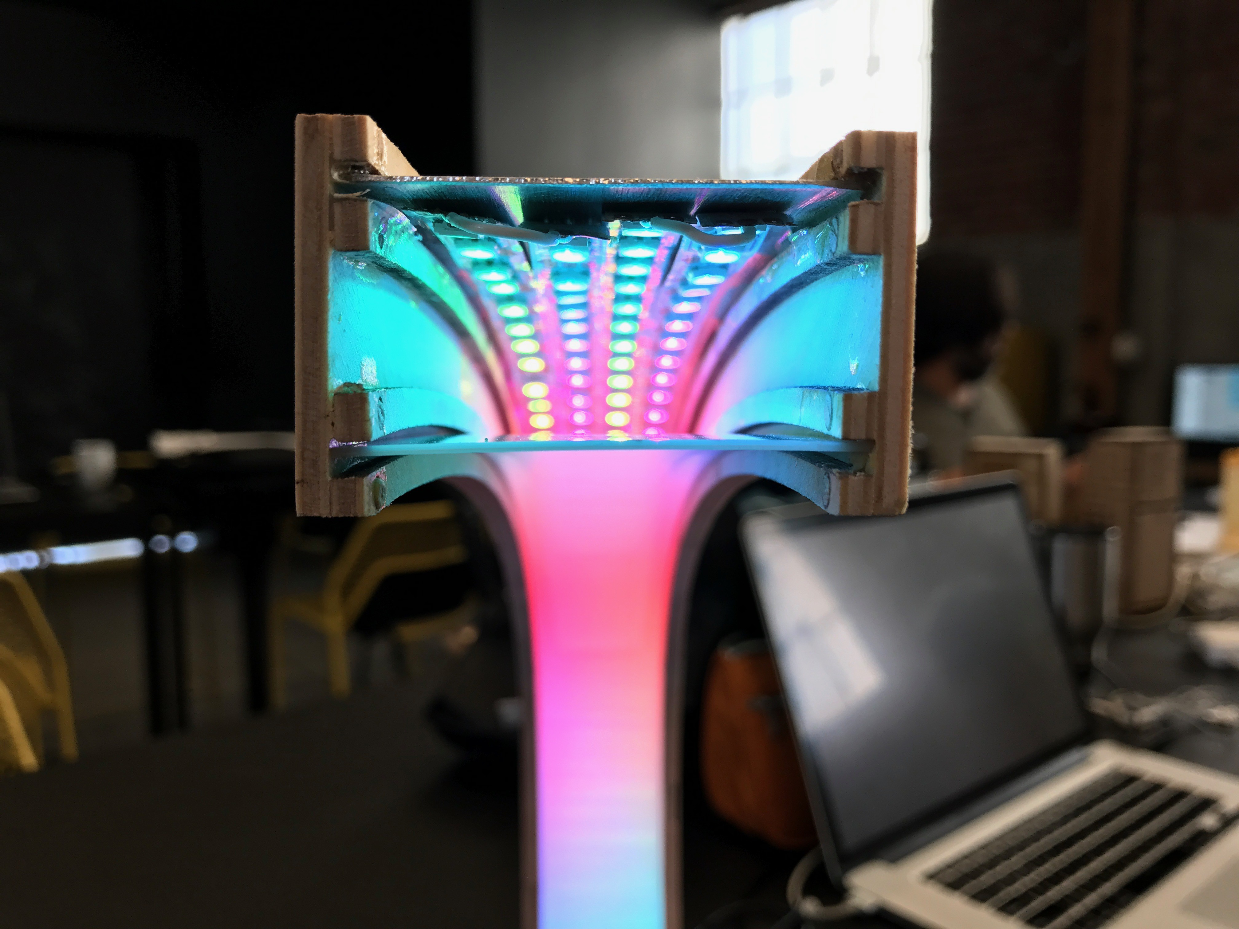
Inspirations:
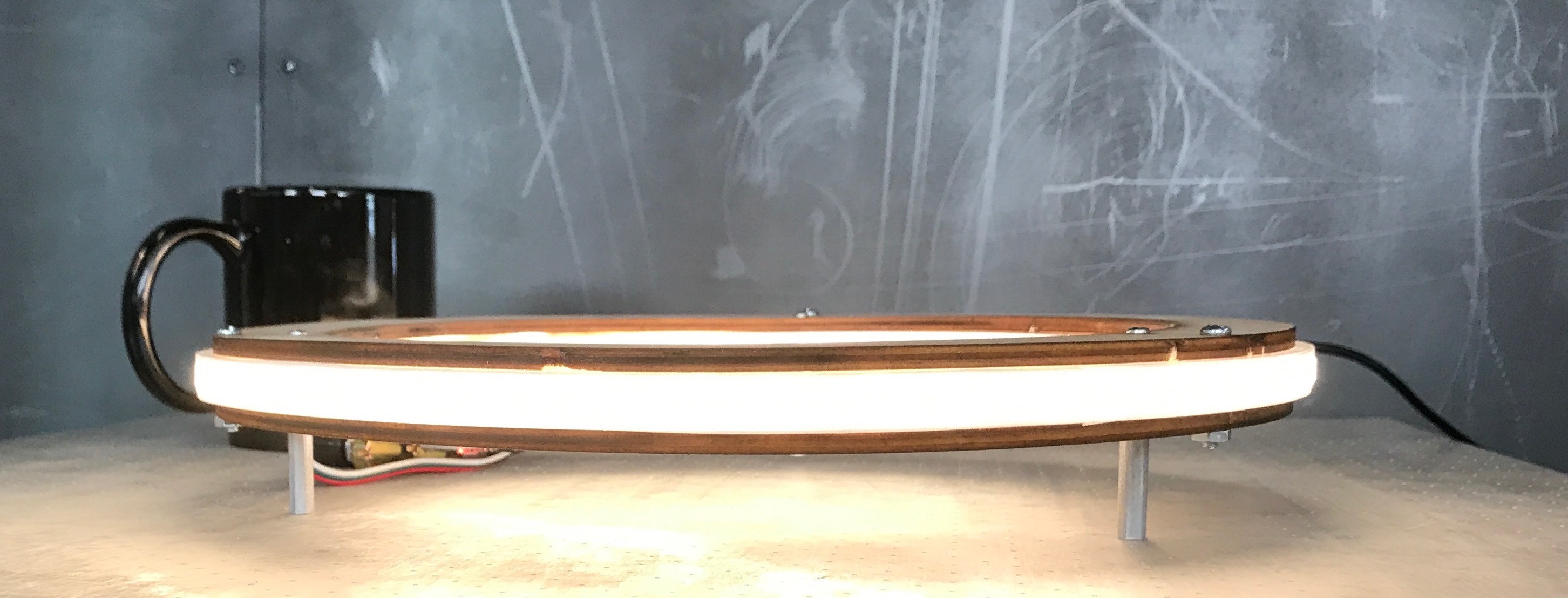
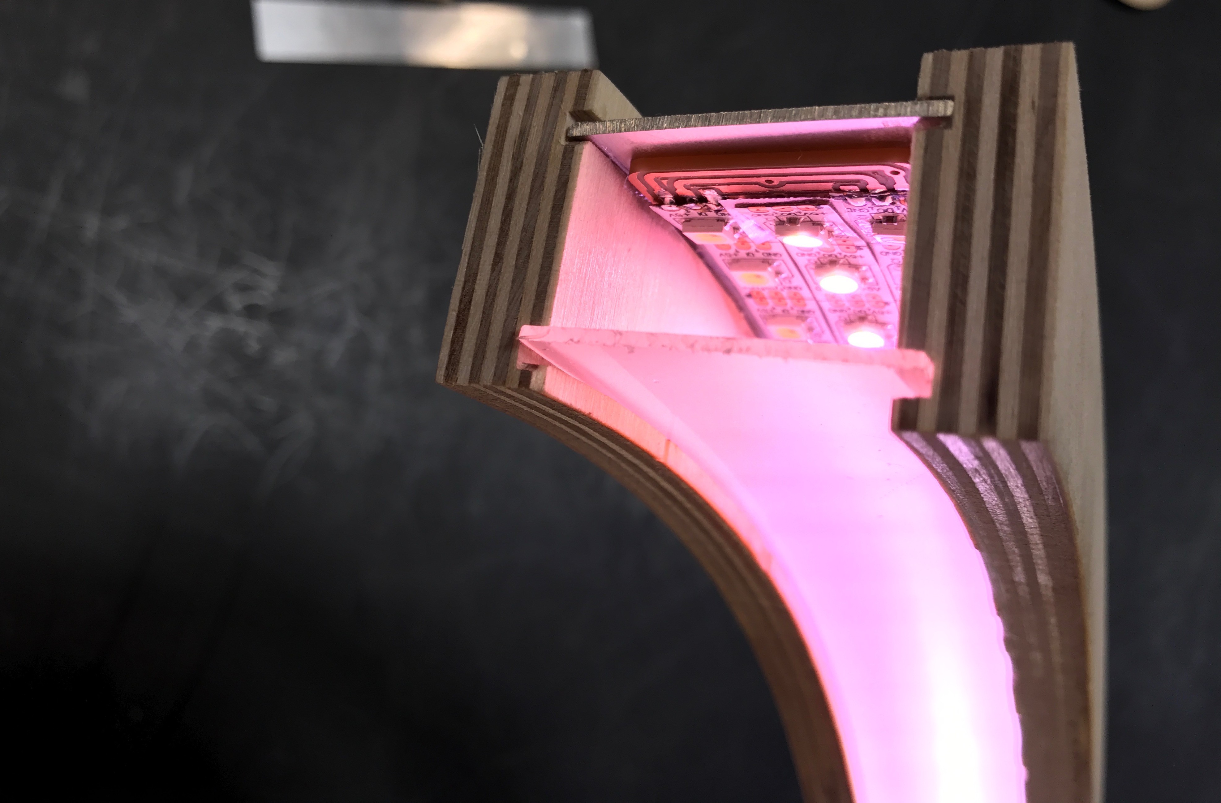
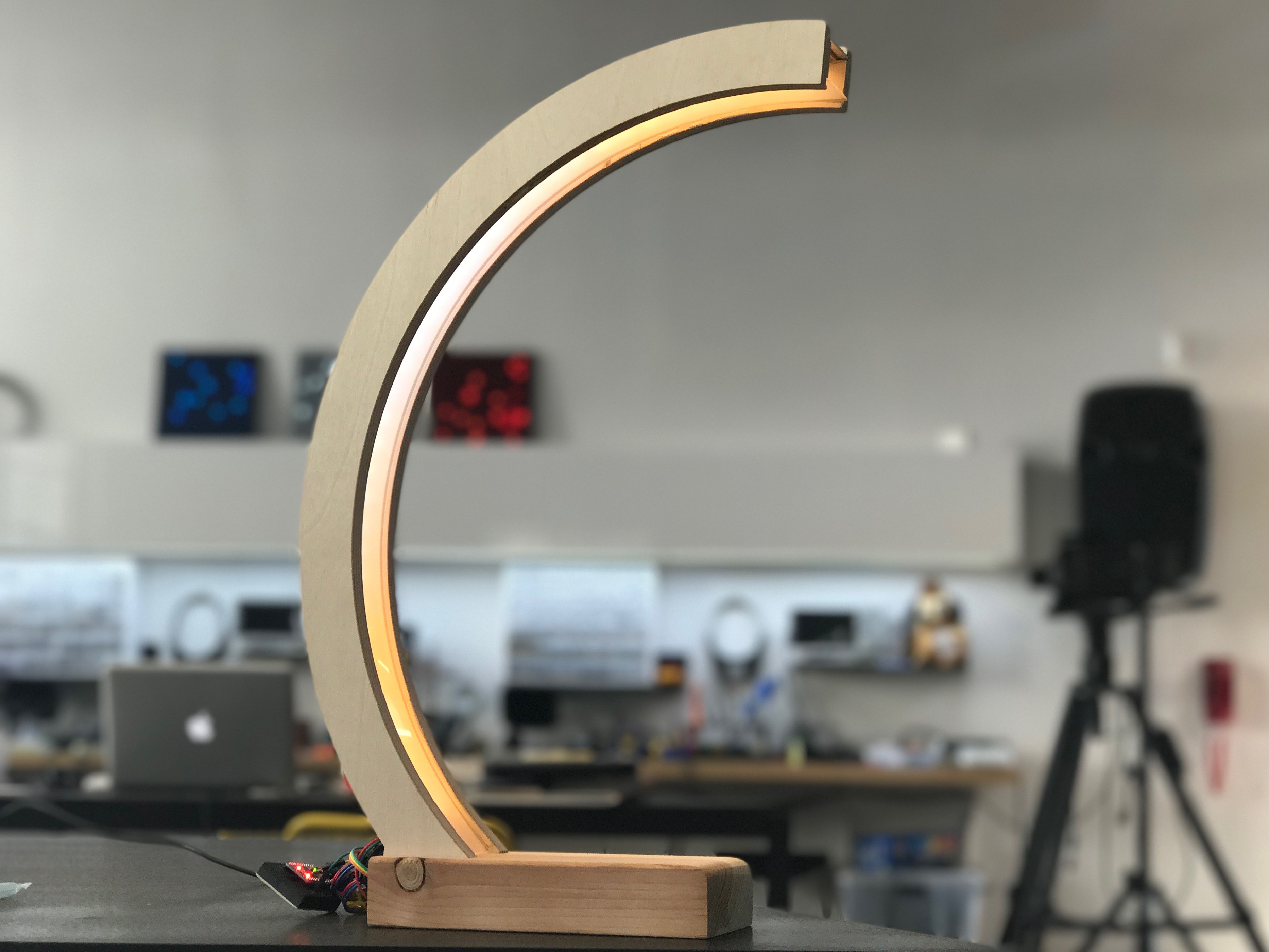
- The look and feel of subsurface scattering of light
- The evolving glittery but calming nature of caustics
- The clean geometric lines of Art Deco
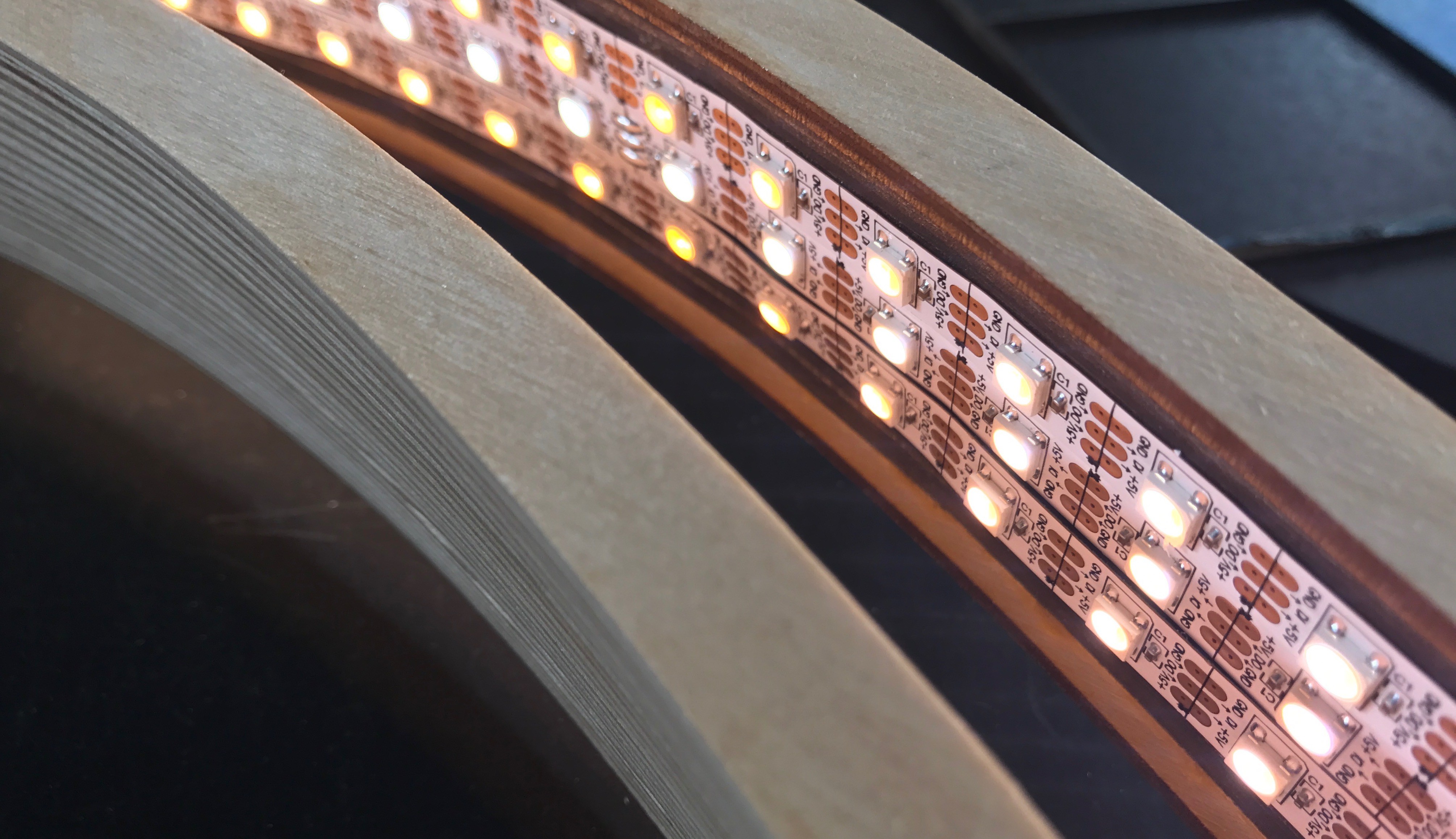
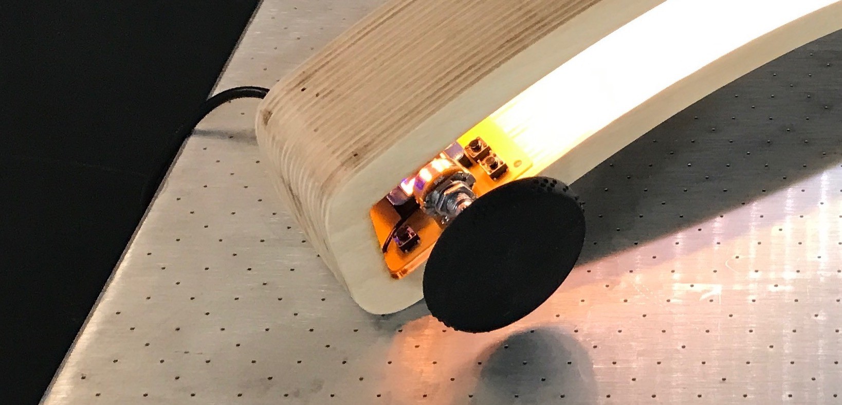
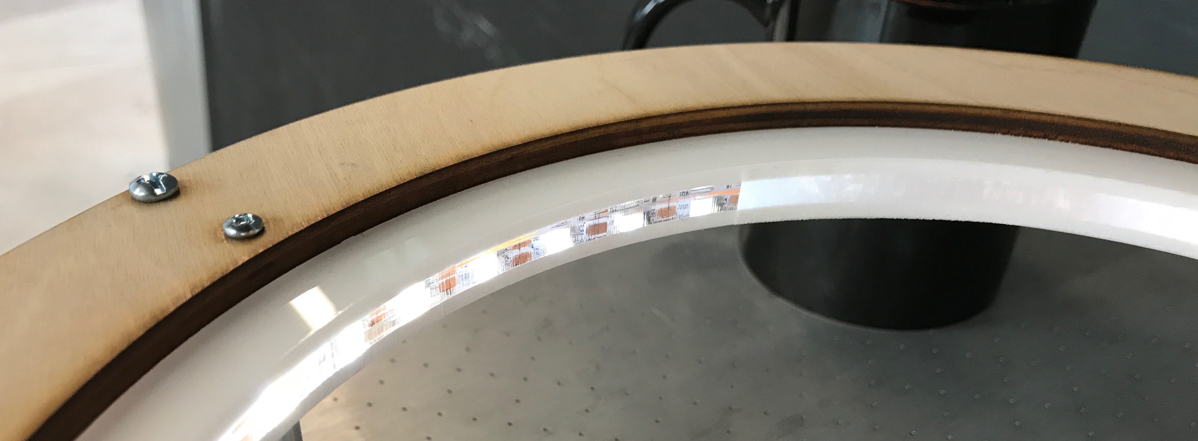
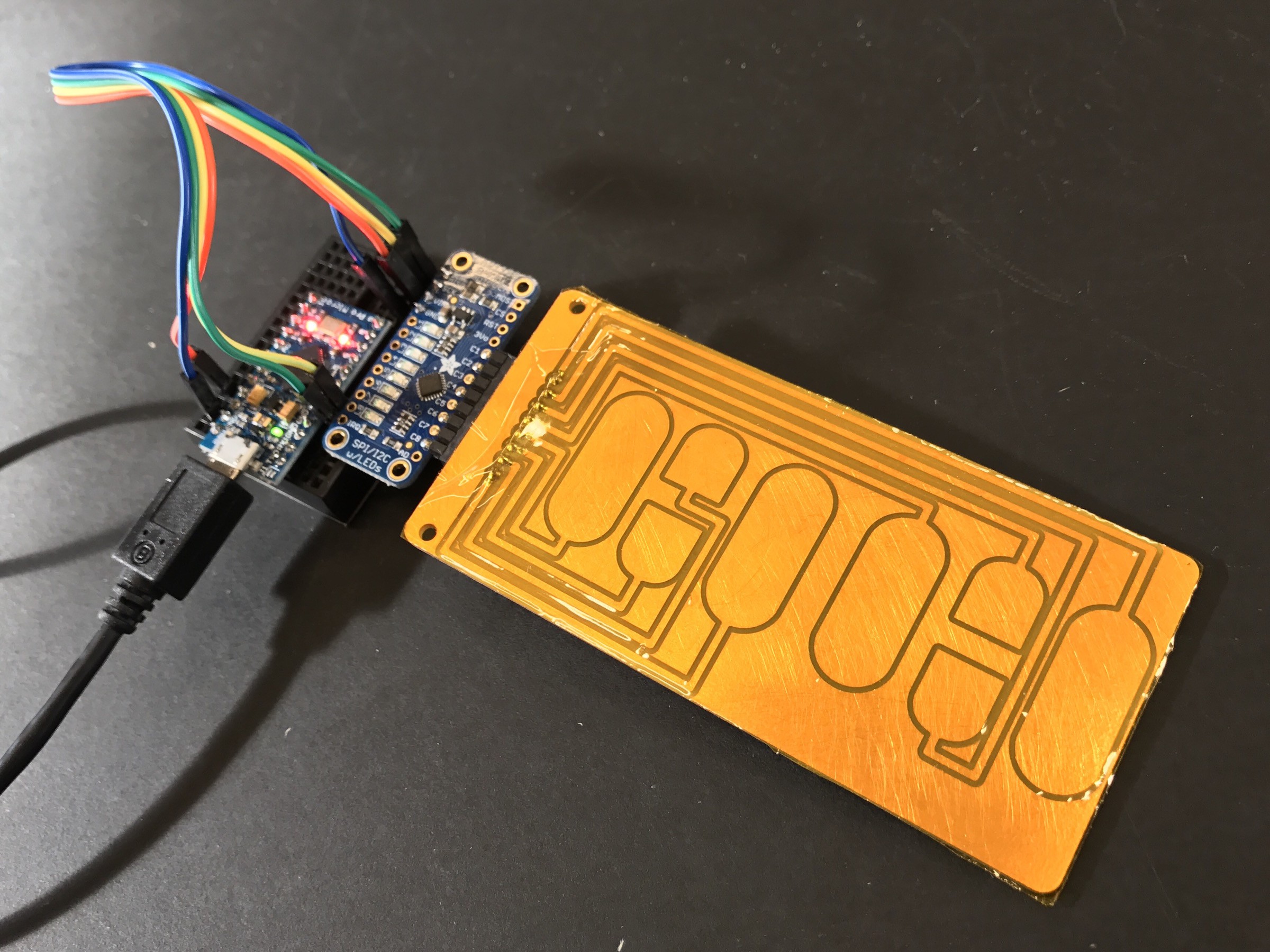
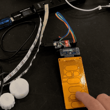
- The power and control of addressable multi-channel LEDs
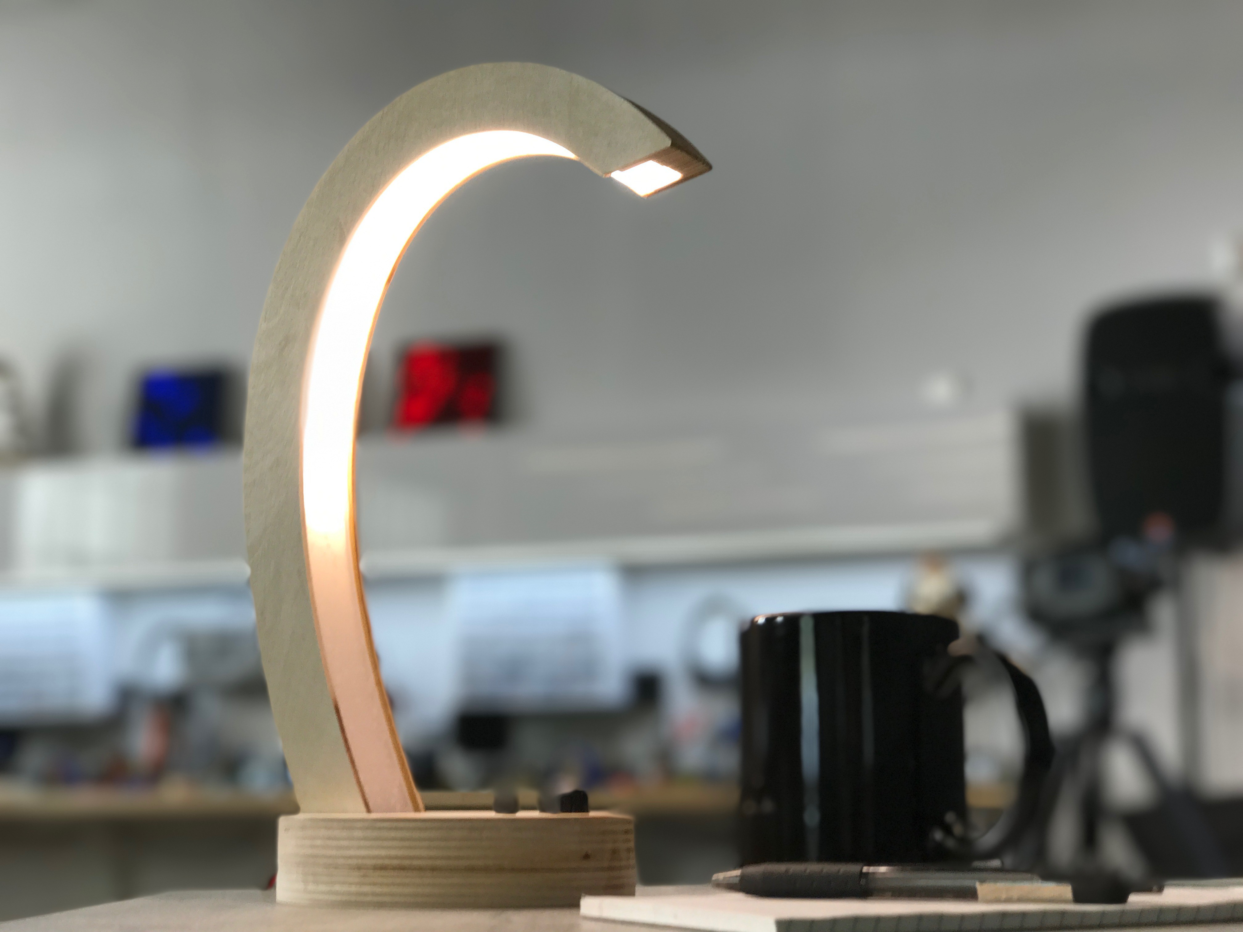
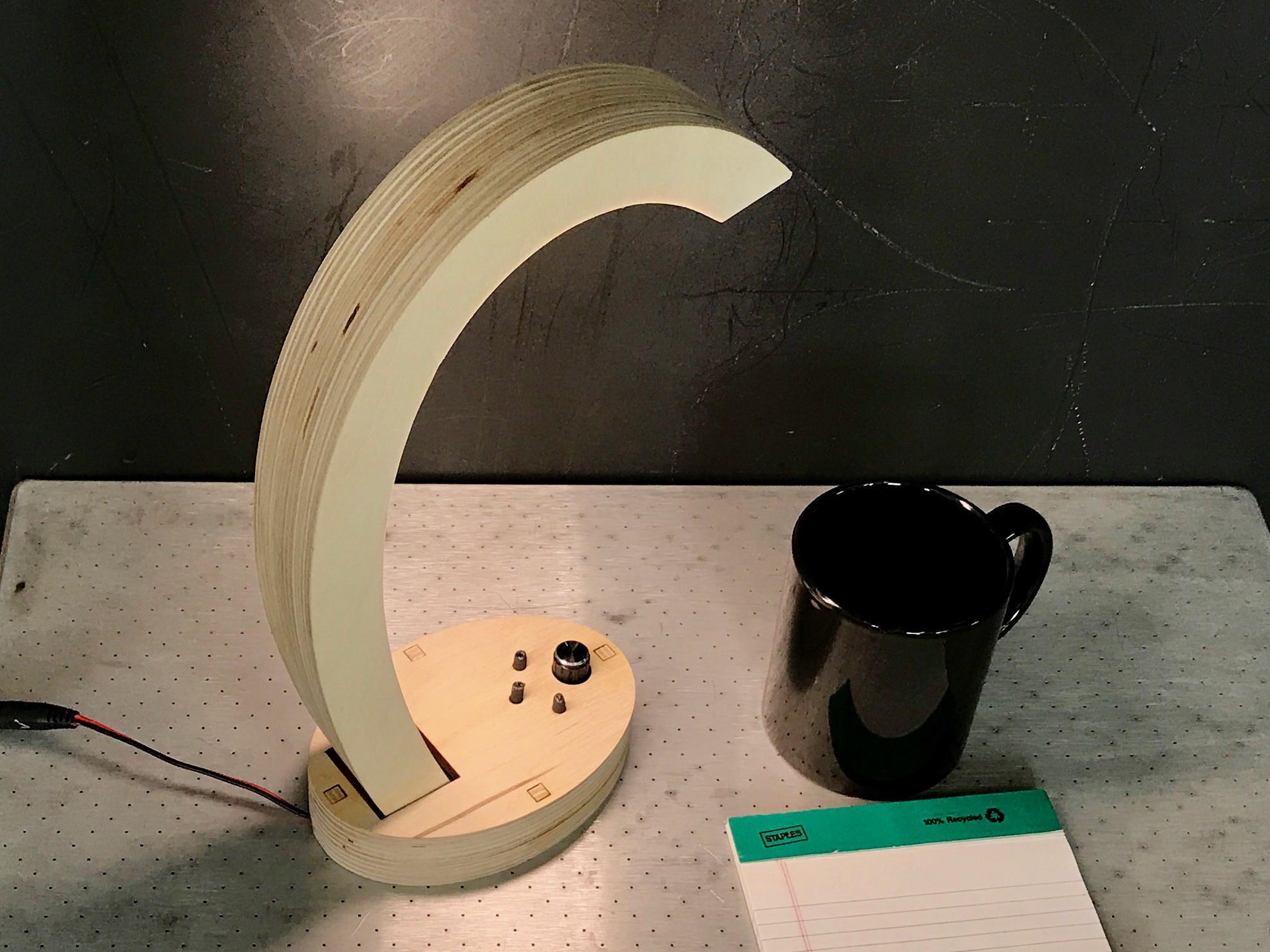
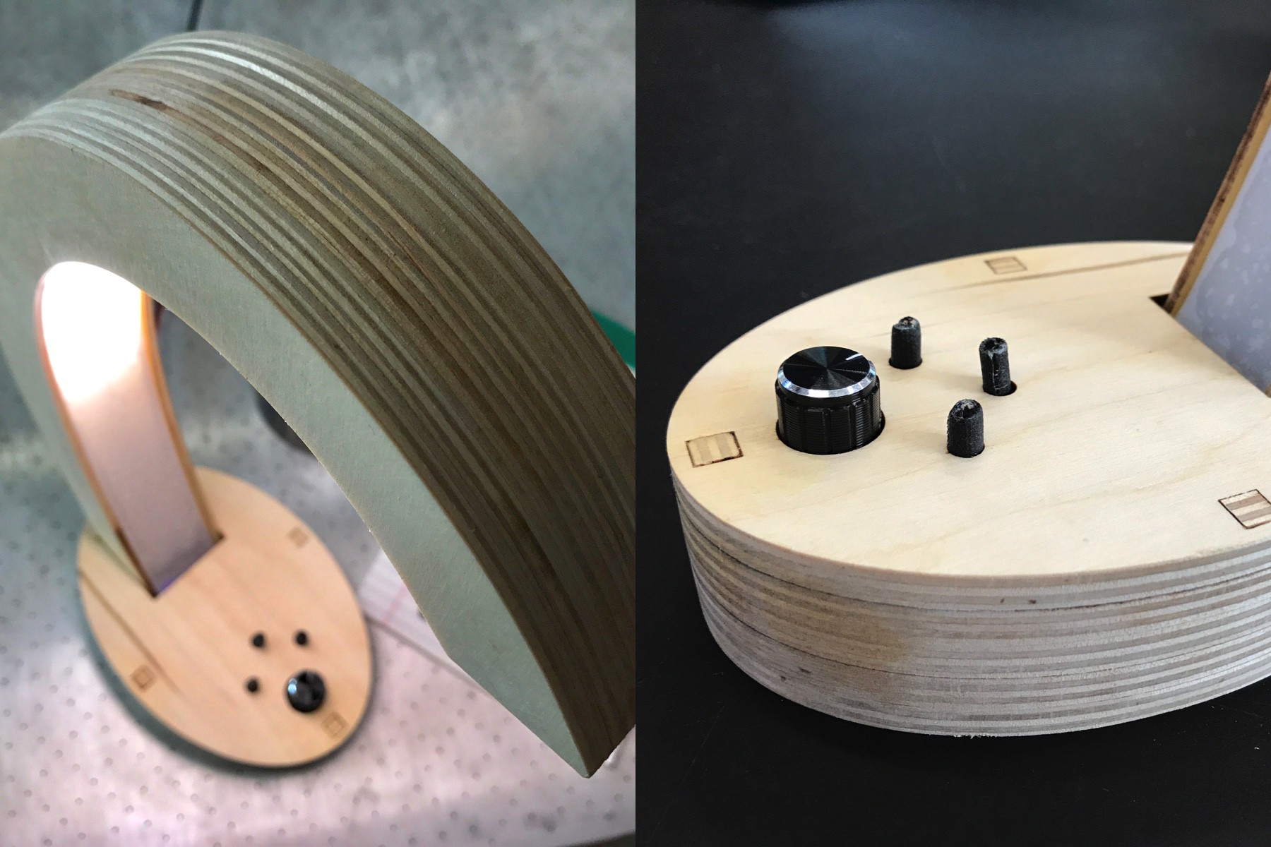
Or.... "Welcome to the spaceship. We are happy to see you!"


 Steve Pomeroy
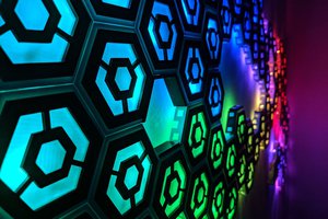
 Josh Cole
 Dirk-WIllem van Gulik
#/media/File:Great_Barracuda,_corals,_sea_urchin_and_Caustic_(optics)_in_Kona,_Hawaii_2009.jpg)
It is a huge addition in the enhancement of room presence. All the designs are very nice. I would love to share it through my website also.