 moosepr
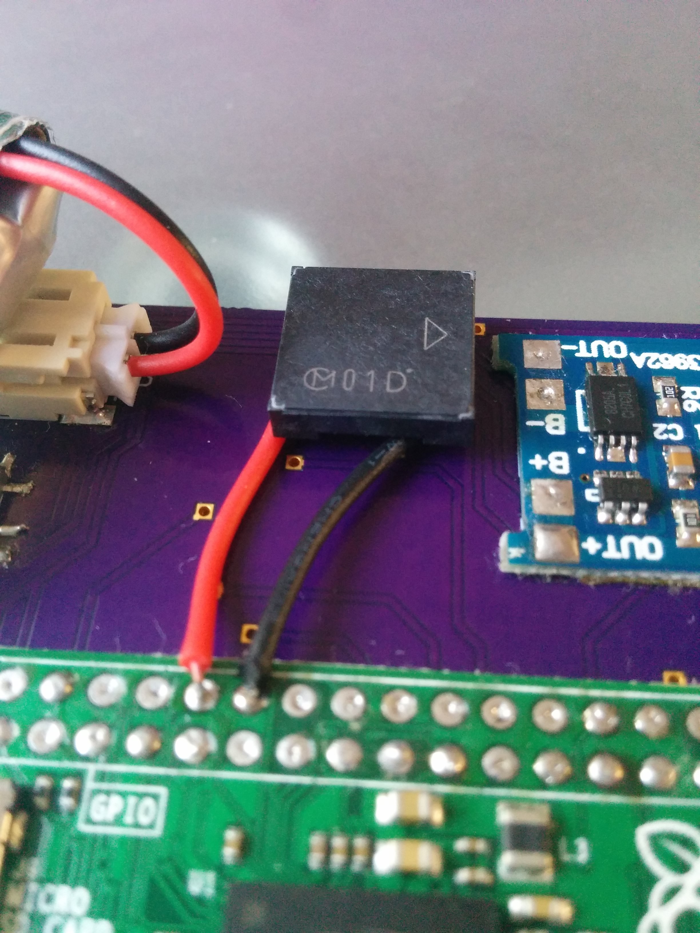
The eagle eyed among you might spot there is no 'boost' circuit!!!
The pi zero is actually quite tolerant, you dont actually need to feed it the full 5v to make it work. The main core of the pi runs on lower voltages, so the majority of it will happily run as low as 3v (i have heard it will run lower, but li-po protection kicks in before we get there), the only real need for the 5v on the pi is USB peripherals, which most will be ok with 3v too!!
Therefore the battery (4.2v-3v) is piped straight into the 5v line on the pi, cutting a boost circuit out of the mix, keeping the power usage below 250mah
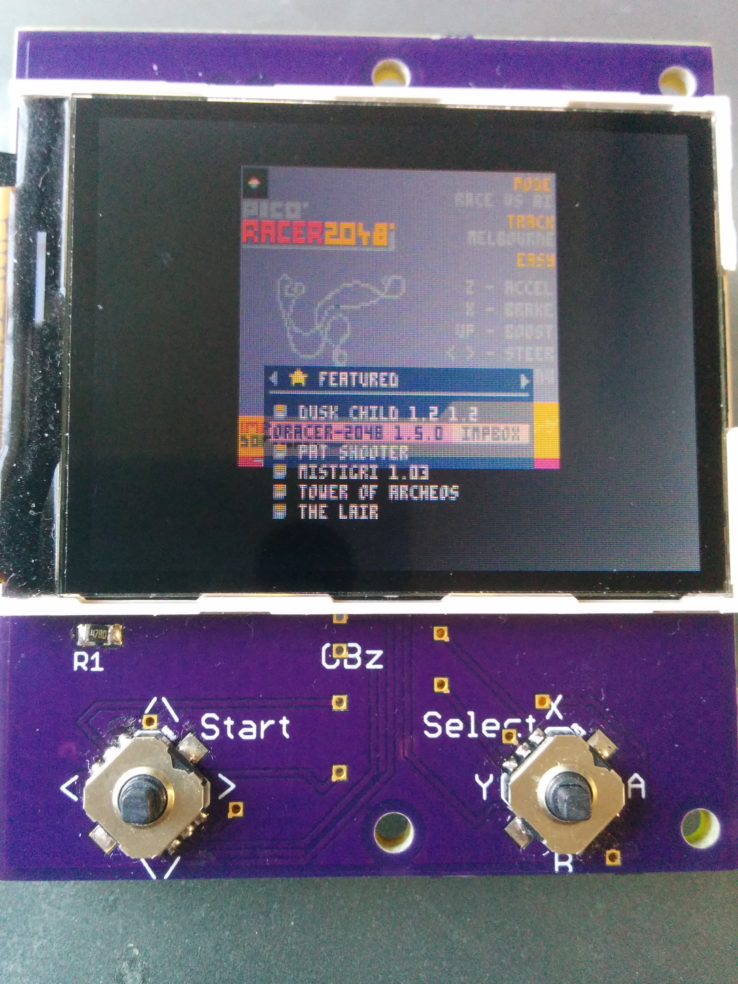
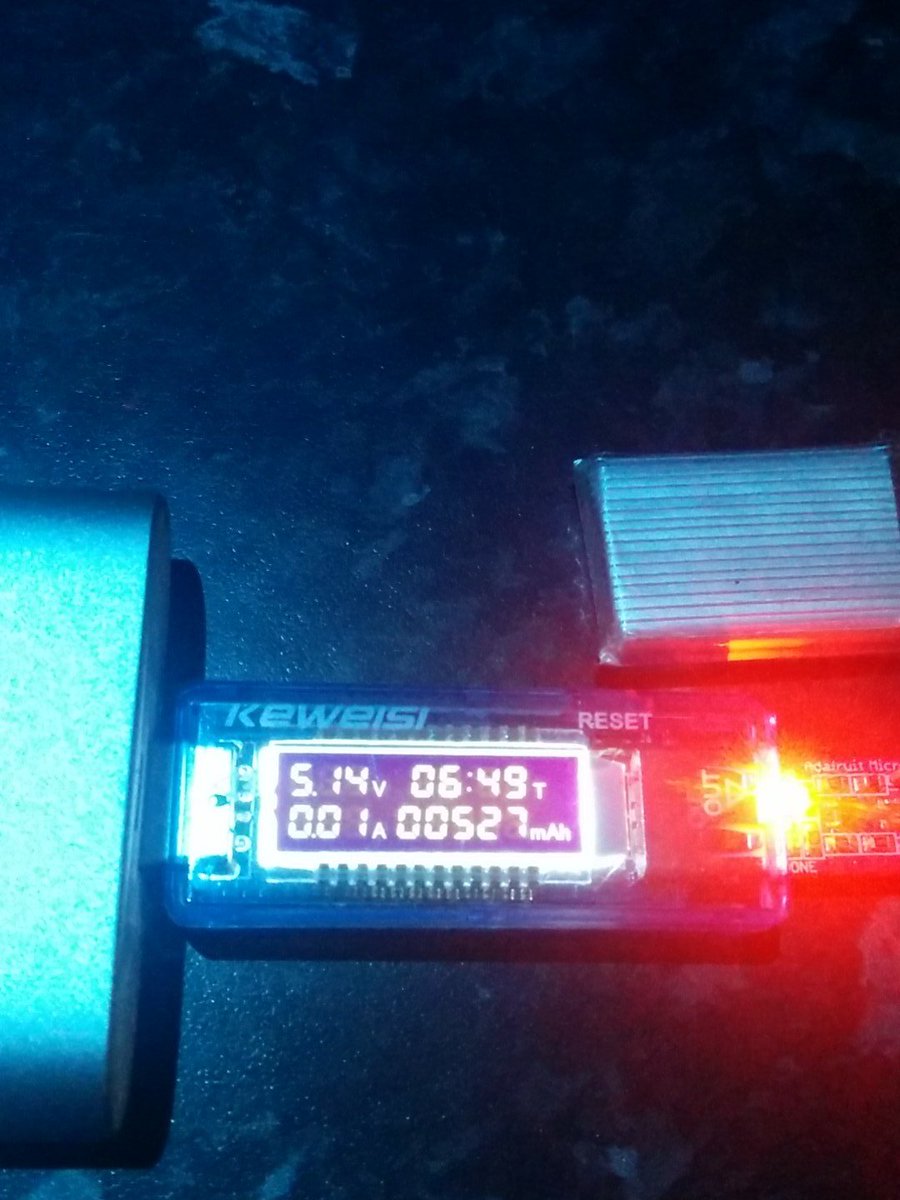 that is a trifle high for a 400mah cell. So i looked back at my ebay purchases and apparently it is supposed to be 650mah!! so it is way off!! some quick napkin math will tell us the draw of the pi
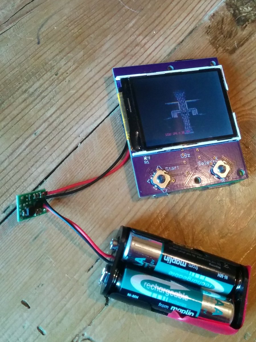 I had my multimeter on the cells to keep an eye on the voltage, and the timer just tipped over the 4:15 mark when the cells were reading 1.6v. once the voltage had dropped below 2v, it started dropping pretty quick!!


 Patrick Van Oosterwijck
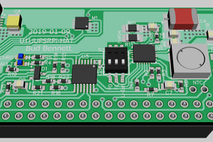
 Bud Bennett
 Emilio P.G. Ficara
is possible to add lora communication mesh and create opensource go tenna machine?
for emergencycommunications