Memristors are variable resistors very similar to potentiometers or rheostats. Instead of turning a wiper dial on top of the pot, the resistance is set by a different mechanism. If current flows through the resistor in one direction, the resistance increases. If current flows in the opposite direction, the resistance decreases. The key is that when the power is removed, the resistance stays the same. This means that the resistor has a memory and thus its name. Therefore, to create a memristor I need to have a resistor which I can adjust in some a non-mechanical fashion, and some way to measure the current going through it.
My first attempt to create a memristor will use a digital potentiometer and an Arduino. The digital pot uses a SPI interface to set the resistance. One advantage of this is that both terminals of the resistor are available. One limitation of this device is that it can only take voltages between 0 and 5 Volts. Also it can only handle up to 2.5mA through the resistor. However, I believe those are reasonable limitations.
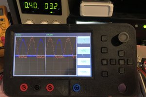
I was planning on measuring the current through the resistor by simply measuring the voltage on each terminal. I will know the resistance since I'm setting it through the SPI interface, so it's just a matter of subtracting one voltage from the other and dividing by the resistance.
The characteristics of a memristor is highly dependent on the material used. I will have different software profiles to simulate different types of memristor technologies. Some resistors only change state when the current exceeds a certain limit. Some change their resistance in a very non-linear fashion. But this can all be software configurable.
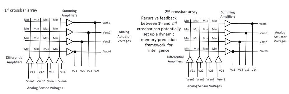
I will also need some test applications. I plan on having at least 4 memristors (using a Quad pot). So I could simulate basic logic gates up to perhaps a very simple neural net.
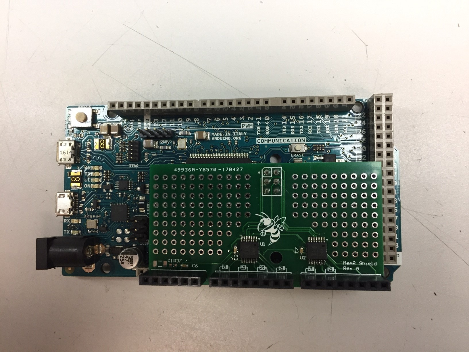
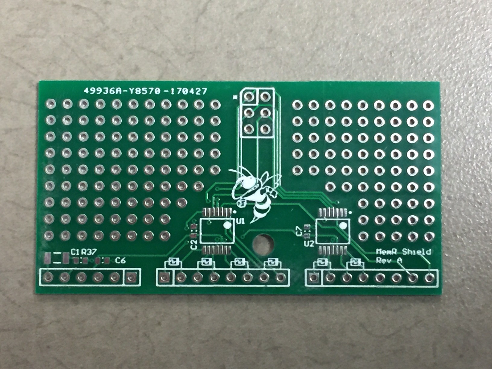
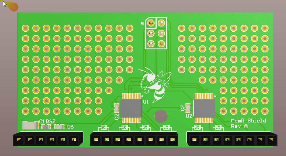
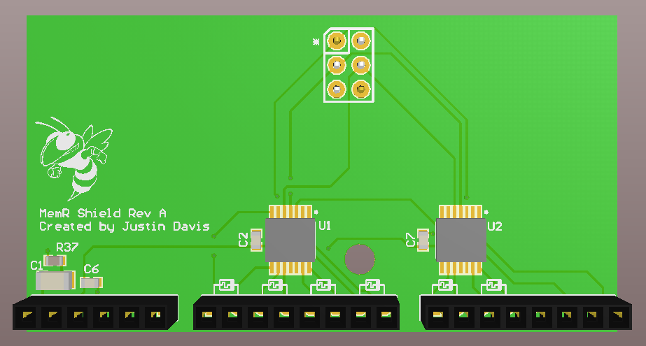
I will eventually make an Arduino shield with some demo applications on board as a memristor development/evaluation kit.
 John Duffy
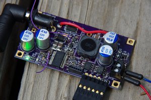
 Jonathan Bruneau
 Yann Guidon / YGDES