 Jon Buford
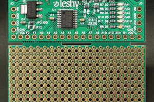
Atomo started out from developing a new motion control board for another project. I saw that prototyping something that was new and complex just was not made any easier with the tools that are on the market. The sensible approach was to strap a dev board onto a protoboard and start wiring things up.
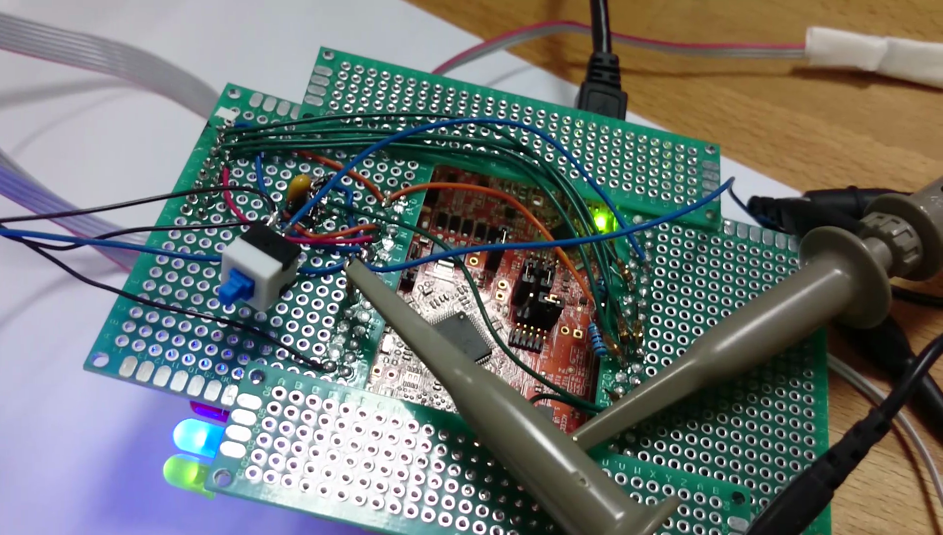
And the results are something like this. It works, but the next step in this process is to either make a PCB that works with the dev board (in this case that wasn't able to provide enough IO) or to do a full new PCB single board design. Both work, but it felt like the process was missing the ability to iterate or add things in a reasonable way.
I started thinking back through other projects I had done, and there were a few commonalities:
1. Cleanly routing or getting enough power was always a bit of a hack and took up more time than it should (this is especially for robotics or other high power things).
2. It was hard to mix together existing shields/HATs or whatever with new designs and have the result to either be a good solution or really suitable for longer use.
3. Debugging new systems was a pain when things went wrong. If a drive transistor was blown out, it was embedded in a board with many other functions that might or might not be interconnected.
I'm sure many readers here have other typical nits with existing dev boards, but I think the overall insight for me was that dev boards are pretty much just that, they usually take care of the bare minimum around the controller, but they are not made to iterate a design easily or to approach a system design in a more simple or logical way.
So, first iteration was a modular system for automation and robotics, you can check it out here: https://hackaday.io/project/13433-atomotionopencnx It was launched on IndieGoGo in September and had a luke-warm reception, but the feedback was pointing to that the approach was good, just perhaps that specific application was not the right fit.
October I went back and started looking at what it would mean to do a more broad purpose system, something that scaled up and down to be both able to make huge robots but also make simple systems that you might use a small Arduino for. We made the first working iteration of the system design then. 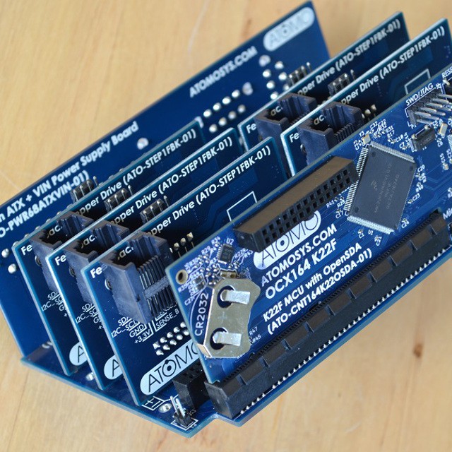
Having gone through this iteration, I finally really got a feel for where we were heading and designed a launch line that included improvements over this version. We went from one controller board to three, and switched from a large K22 (NXP ARM Cortex m4) to a smaller K22 and a larger K64 which were better supported with tools for flashing and the like. The smaller board based on the K22 is more or less based on the FRDM-K22 dev board, but we switched to a KL26 controller for the OpenSDA/DAPLink USB flashing interface, same as used in the Microbit.
 Now, doing the design for all of these boards in 10 weeks was a bit of an effort. We used KiCAD for the schematic and layout. I had two people working on it (a contractor and myself) for the whole time. The interfaces, like the module connectors, were fixed as early on as possible, but there were some later changes that we only found after more or less completing the full round of designs. So, that 10 weeks was actually two spins of some of these boards.
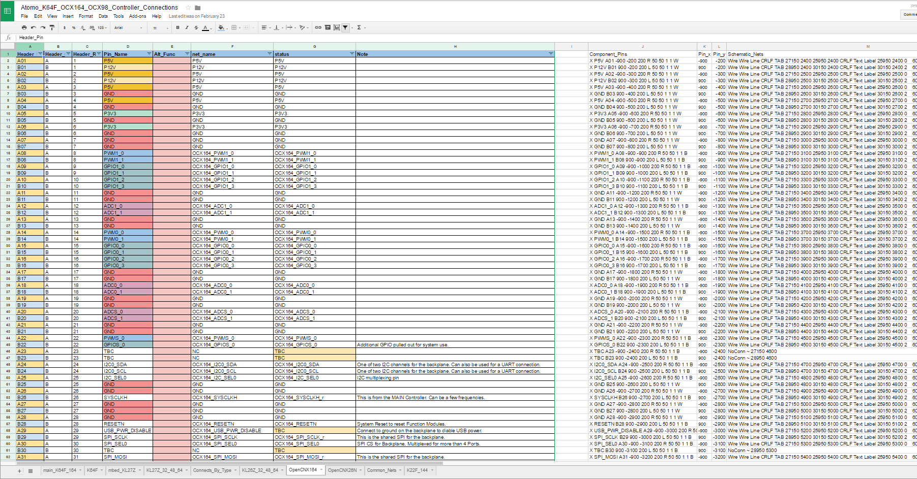 In order to sort out the connections to all of the modules, I put everything into spreadsheets with checking back and forth to look for missing connections and duplicate uses of different port functions. I then generated the information for the KiCAD schematic from this and created the main components and connections in this way. By doing this, the two controller boards using the K64 were able to use the same pins between them for the first four modules and I was able to save a lot of time with keeping track of what was what. There are pin configuration tools that help validate on the duplicates side, but there are not any tools out there that do the checking between different interfaces, other than just the schematic itself....


 fruchti
 Edward Li
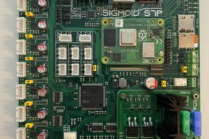
 pkElectronics
 Miroslav Zuzelka
I did something a little bit like this for a vehicle tracking outfit I did some work for 12 years ago. We had been having great luck with 68HC11 so I built a board that would make everything we had ever built and a lot more including the new modems and 2 or 3 old modems that were really cheap. They were working great until a fellow fresh out of collge and still wet behind the ears that worked for one of our jobbers sent us board his bosses had him working on that was a duplicate of ours that cost small farction what ours did. It was his way of giving us a heads up about what was going on. I hired him the next day and it was the best move we ever made. He had his $0.75 chip running on our $18 dollar board in 9 hours and worked every bit as good as a $18 dollar single chip 68HC11 or an $85.00 dollar 68HC11 expanded board did. at the cost of $2.50 socket to match the pins.
The expansion boards sure look nice I just hope it works as well as they look and not like mind did.