 Yann Guidon / YGDES
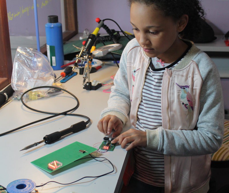
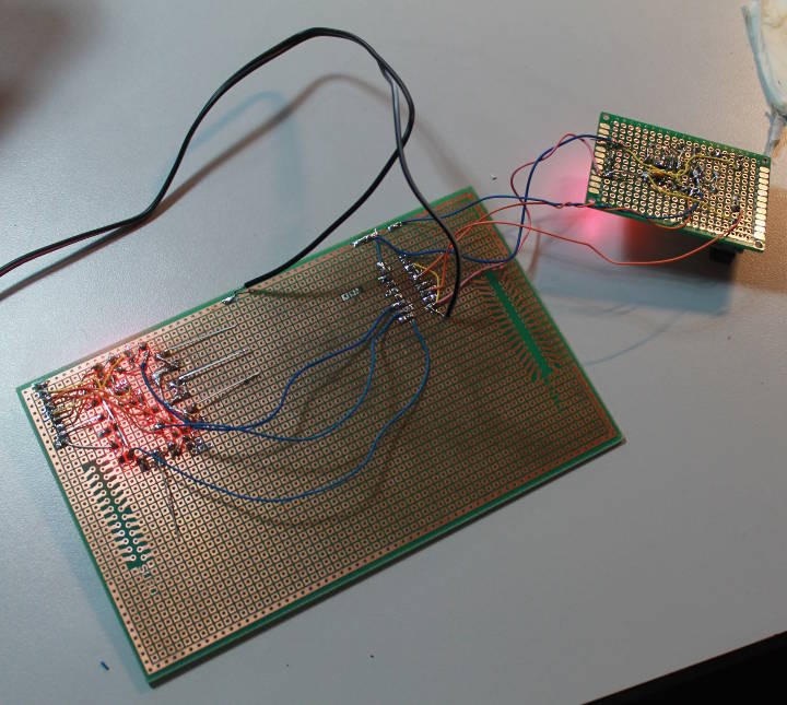
Today we were able to finish 3 segments (2×6LED and 1×4LED, with their 330 Ohms series resistors) and the signal generator so we added the '595.
The signal generator helps us control the segments in real time so we could measure the currents. The procedure is easy when there is no 595: just insert a milliampmeter between the power supply (5.5V when open) and the desired segment. We found 13mA for 6LED and almost 10mA for 4LED segments. That's more than what we calculated and rated !
Since the 595 can supply at most 70mA, each segment should draw at most 70/8=9mA. But there are two factors that make this measurement misleading :
- The PSU is barely loaded and drops to 5.4V when mildly loaded. We calculated for 5V, yet here we get +10% bonus.
- The '595 has some inner resistance for each data pin so the segment voltage will be lower.
- The '595 has a single power pin through which all the current goes, which adds more resistance : more lit LEDs will drop the segments' voltage even more...
3 is why we need to turn ALL the segments ON at the same time to make meaningful measurements. For now we have only 3.
When the '595 is soldered we can't insert the milliampmeter in the signal. However we can measure the current indirectly by reading the resistor's drop : I=U/R.
We get about 1.4V/330=4mA per pair of LED, which is the expected value : 6LED should be about 12mA and 4LED should be about 4mA. This gives an average of 10mA/segment, which will slightly drop as the PSU voltage reaches 5V and more segments are turned on (they are not all ON at the same time)
So this incomplete prototype has shown that the design goals are met but we need to test with ALL the segments at the same time for a definitive measurement.
Anyway we finally have something to play with !
Discussions
Become a Hackaday.io Member
Create an account to leave a comment. Already have an account? Log In.