 Radu Constantin
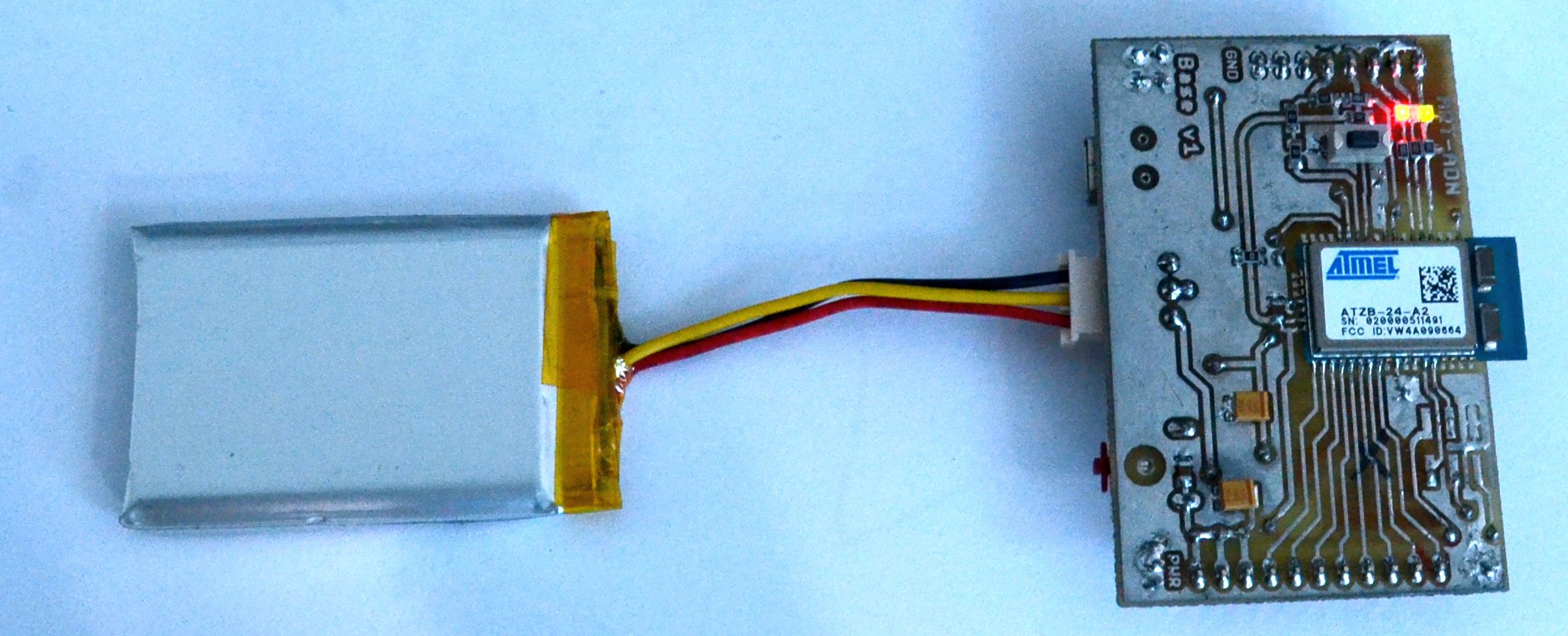
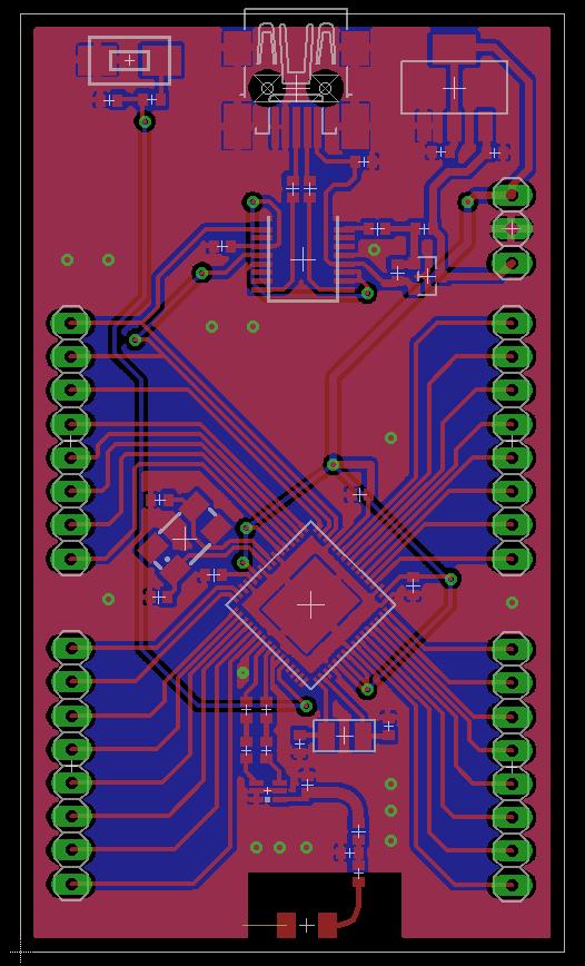
System design:

Got so far (v0.2):
- calibrated the matching circuit on the antenna
- added RF antenna out for matching and external antenna connection.
- all pins are 2.54 mm
- JTAG and SPI separate interfaces
- power led
ToDo (v0.3):
- finish the project website (http://www.nandfarm.com)
- evaluate the new the Atmel Cortex M0+ ZigBee enabled chips
- make it compatible with Atmel Over The Air Upload (OTAU) bootloader
- change the FTDI with a Cypress CY7C65211
- Kickstarter?


 NuclearPhoenix
 Madison
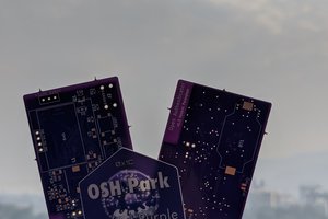
 Vedant Paranjape
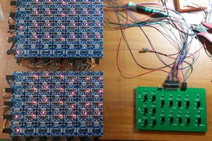
 Dave's Dev Lab