0%
0%
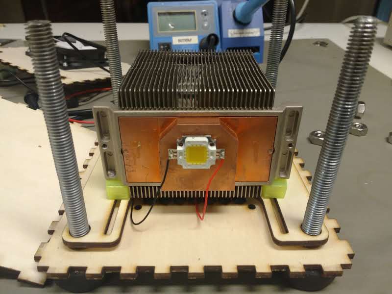
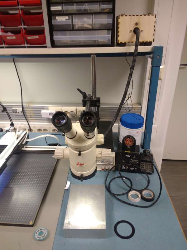
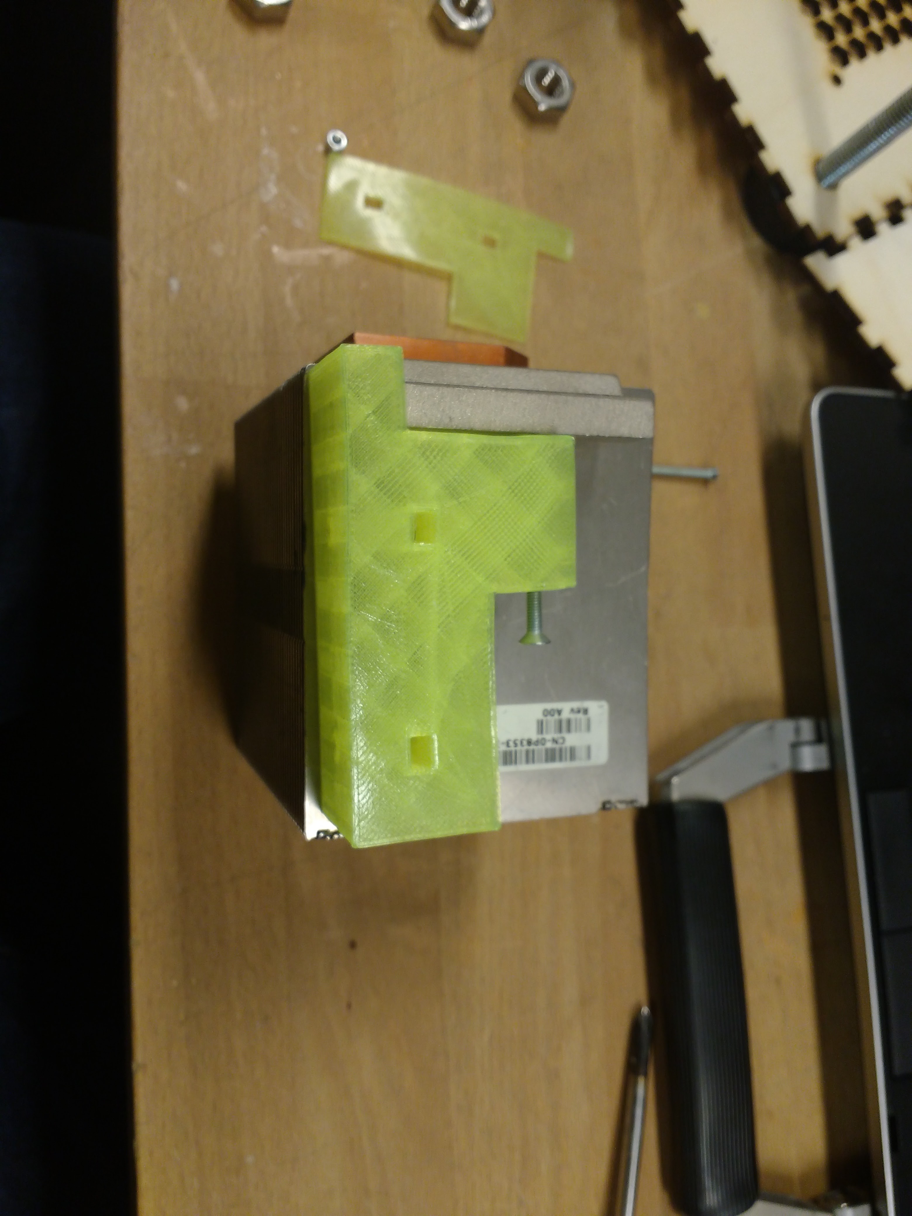
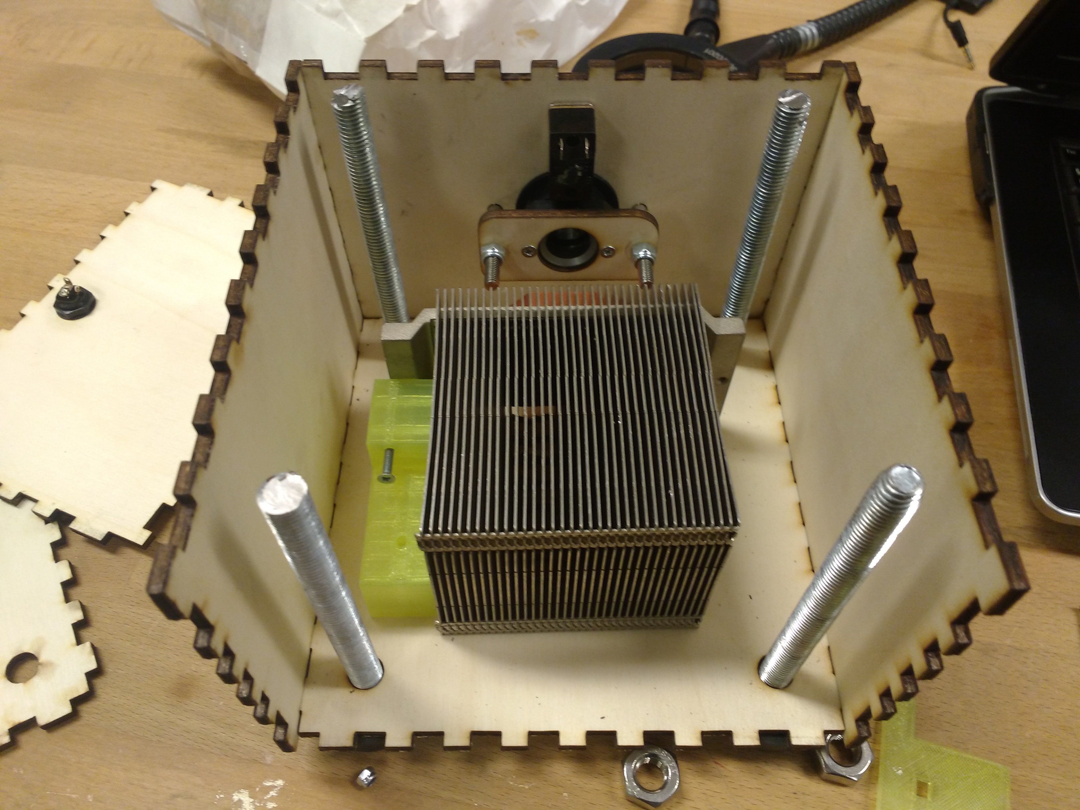
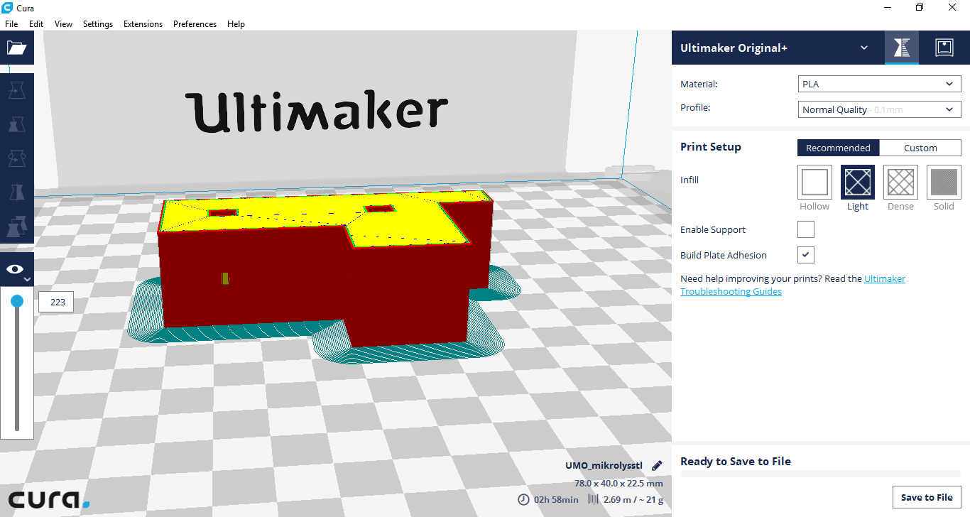
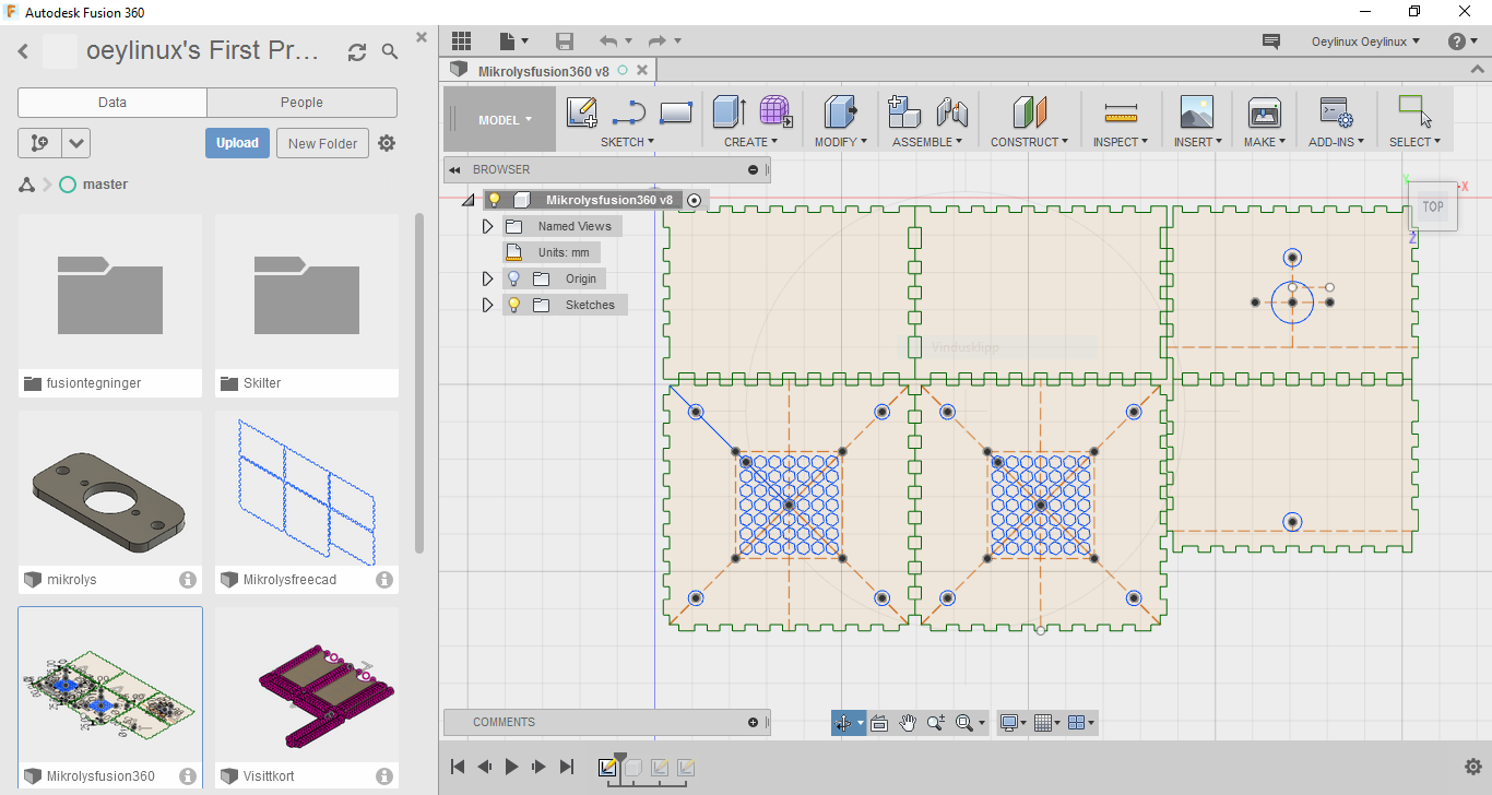
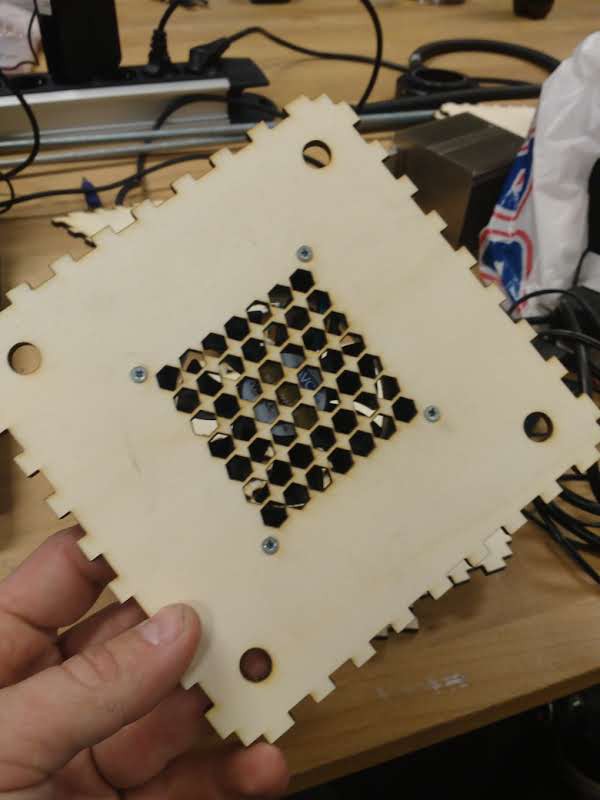
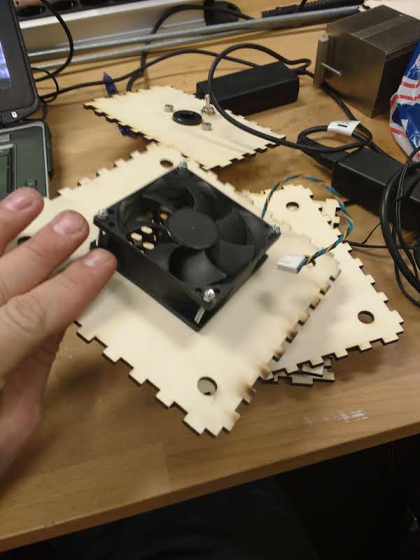
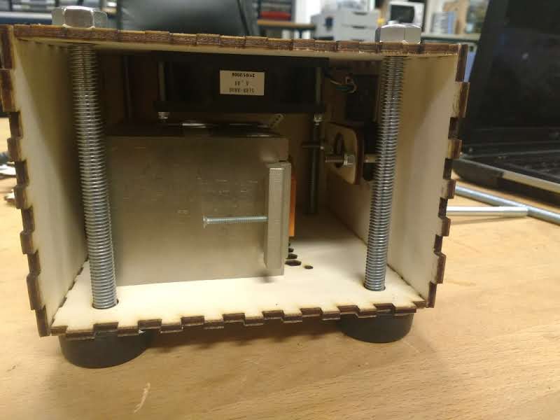
Lightsource for a microscope ringlight
A project with the mission to replace an old lightsource for a microscope ringlight from leica.
 Øystein
Become a Hackaday.io member
Already have an account? Log in.
Just one more thing
To make the experience fit your profile, pick a username and tell us what interests you.
Pick an awesome username
hackaday.io/
Your profile's URL: hackaday.io/username. Max 25 alphanumeric characters.
Pick a few interests
Projects that share your interests
People that share your interests

 Colin Russell-Conway
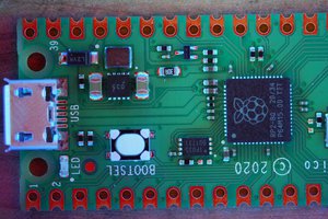
 Sina Roughani
 scubabear
 Alain d'Espaignet
If youre interested, it was a leica cls 150m