 gruenst
Idea
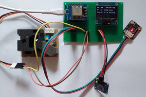
The project is basically to solder 3 PT breakout boards (MAX31865), connect it with the Feather Adalogger, incorporate this into a standalone embedded system with switches and plugs, and program it to fulfil your needs.
Libraries
Adafruit SSD1306 (OLED) and MAX31865 libraries were used, the GFX library is necessary.
Thoughts
A schematic was skipped due to laziness, apologies for that. This was the first project of this kind, so improvements on the design and programming are apparent. The reference resistors were chosen for their temperature range and accuracy, which might seem a bit excessive given the accuracies of the overall design. The 3-wire mode of the MAX31865 was neglected as, to the author's opinion, there is hardly any need, and it might make things unnecessarily complicated. The layout could easily be made smaller using SMD components, but the chosen housing was already amongst the smallest found for waterproof project cases, and the possibility to exchange the single IC components was preferred as it adds a neat feature to it rather than cutting on board space.
Anyway! I do like the project. I hope so do you.
Shoutouts to this project: http://hallard.me/max31865/
Possible improvements
- Adding a real-time clock breakout board
- Going for an even smaller setup (possibly using the Adafruit Pro Trinket 3V)
- http://hackaday.com/2014/11/25/better-spi-bus-design/
- Using one single MAX31865 with a multiplexer, and possibly more inputs than 3
- SP3T switches as PT100/PT1000 selectors instead of 3x SPST
- switches as 2W/4W selectors, possibly push buttons
- adding a precision analogue reference voltage for gaining accuracy
- locating the power on/off switch further towards the top end, as it is located directly underneath the battery plug, so a bit unfeasable
- plugs for PT sensors, additional to screw terminals
- design on one tiny PCB with Feather dimensions, to achieve one single PCB stack
 Matias N.
 Clovis Fritzen
 Kody Alan Rogers