 Neil K. Sheridan
Here we are going to make a circuit to isolate the 12v IR illumination devices from the 5v raspberry pi! We need to switch them on using GPIO out from the pi, but we don't want to expose our raspberry pi to any risk of it getting 12 volts!
Now, this circuit will be quite tricky if you are not used to working with its two main electronic components: a transistor and an optocoupler/optoisolator!
Let's first investigate what these are:
WHAT IS A TRANSISTOR AND HOW DOES IT WORK?
Now, in our circuit we want to turn on the IR illumination device. We could do this with a push-button switch! But computers can't push switches! Well, we could make a robotic hand to push the switch I suppose, but that would be a bit much! So we use transistors in order to enable computers to 'push' switches!
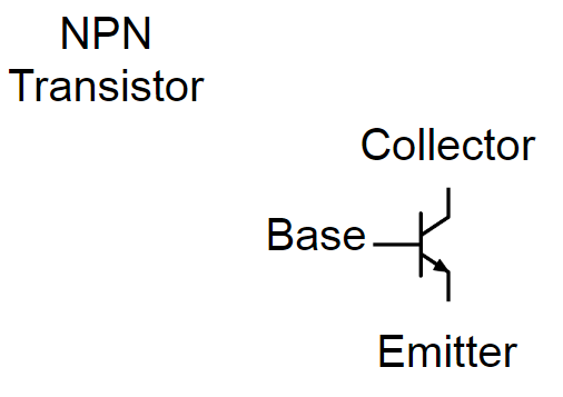
See it does look a bit switch like doesn't it! There are different types of transistors, but we are using a bipolar junction transistor (BJT) There are two different structures for these bipolar junction transistors: NPN and PNP. The structure is the type of semiconducting materials the transistor uses. You can read more about these here: https://en.wikipedia.org/wiki/Bipolar_junction_transistor#NPN
Anyway, all we need to be concerned about is that we can switch the transistor on or off by altering the voltage applied to the base. If we apply a voltage to the base, then current will flow between the collector and the emitter - so switching our circuit on! If we don't apply a voltage to the base, then no significant current will flow from collector to emitter - and our circuit will be switched off!
So, as you can see below, there are four pins on the (BJT) transistor I'm using:
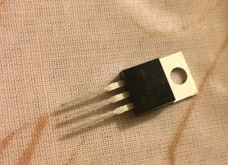
1. BASE
2. COLLECTOR
3. EMITTER
4. COLLECTOR (the top one)
* the datasheet should explain which pin is number 1!
Now we'll build a test circuit using batteries. Here's a simple test circuit we can setup using a breadboard, one resistor, an LED, a 9v battery, a smaller battery, and our BJT (NPN):
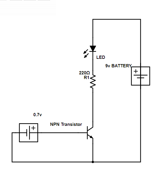
So, you should have a good idea of how a BJT functions now! Below you can see my circuit in action. Note there are two batteries: one for the LED circuit, and one to send voltage to the base pin on the transistor. In this video, there's also a resistor between the battery (which is 6v rather than 0.7v) and the transistor base pin:
WHAT IS AN OPTOISOLATOR AND HOW DOES IT WORK?
An optocoupler, or optoisolater, is a component that can allow two circuits to communicate with each other light instead of electrical signals. So the circuits are completely isolated electrically, communicating only via light. In the same way as our synapses electrically isolate our neurons from each other, communicating only with chemicals. The optocoupler uses semiconducting materials and LEDs to perform this function.
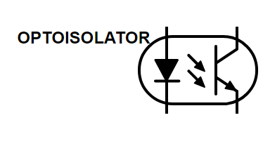
As you can see in the above schematic - it is basically an LED and a transistor. The LED on the left side is acting on the base of the transistor (on the right side).
So in an optoisolator we have pin arrangement of:
1. Anode for the LED (+ve)
2. Cathode for the LED (-ve)
3. Emitter for transistor
4. Collector for transistor
Well, that's if it is 4 pin. Many are 6 pin, so we might have:
1. Anode for the LED (+ve)
2. Cathode for the LED (-ve)
4. Emitter for transistor
5. Collector for transistor
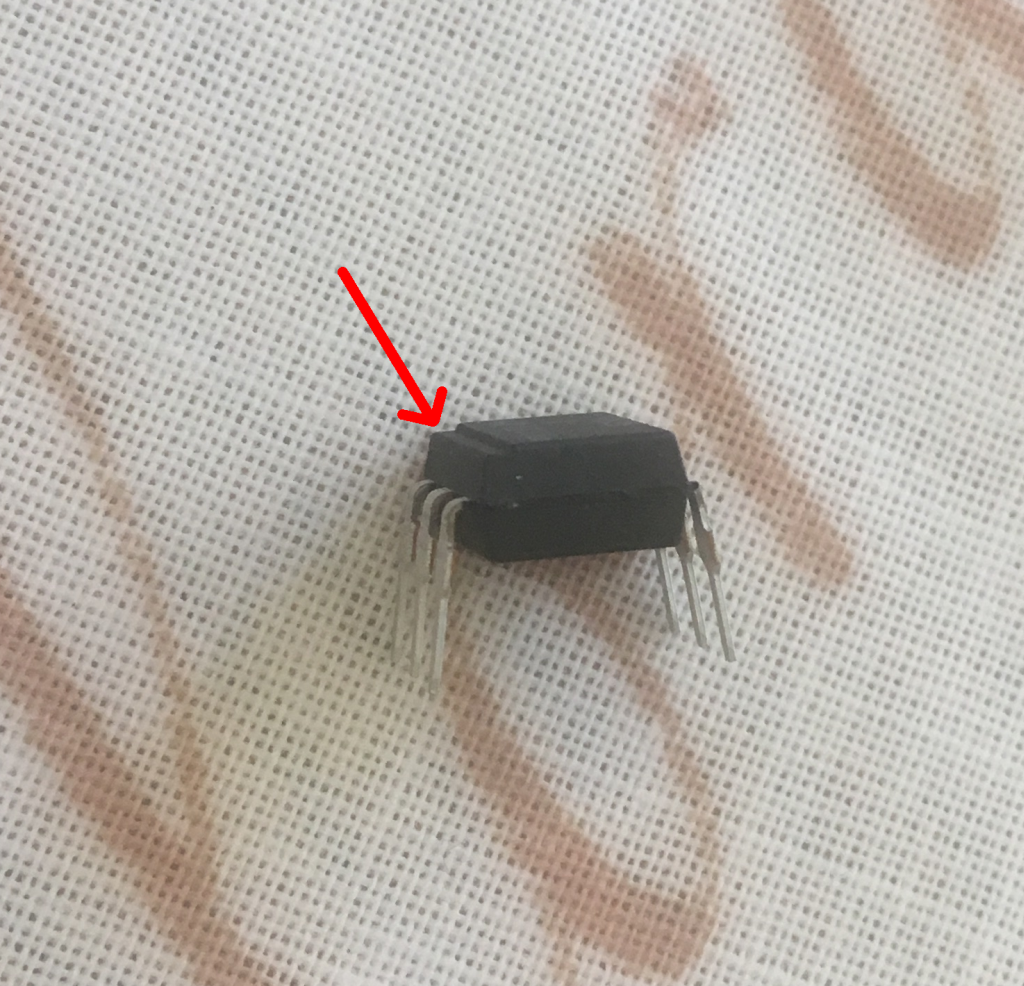
I have a 6 pin. The 4N25X. Datasheet: http://www.farnell.com/datasheets/90919.pdf
If you look at the datasheet you can also find out which side is for the LED, and so which is pin 1! In my case it had a notch on the LED side (see image below). It's very important to check your datasheet - it's not a good idea to just muddle through by connecting things and seeing if it works!
Ok, so we got the idea of an optoisolator! In our scenario, we use it because we don't want the 12v IR illumination device in electrical contact with the raspberry pi (5v)! Of course, you can isolate even DC and AC circuits with these too!
Right, so let's set up two circuits and optically isolated them with an optocoupler now! We will also use our BJT to switch the optically isolated circuit (with the LED) on and off from the Raspberry Pi GPIO with 3.3v!
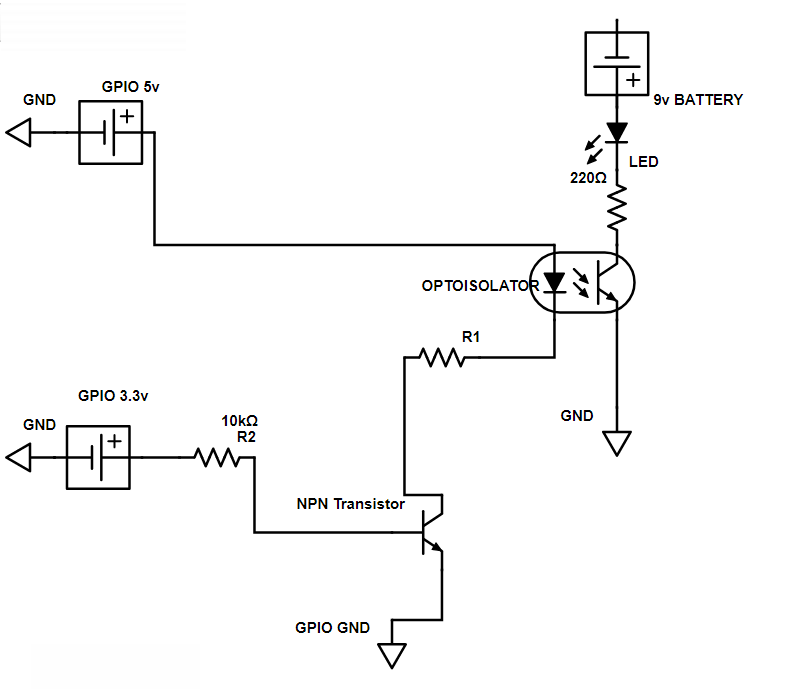
So here we have the pi send 5v to the anode of the optoisolator, and we have a transistor that only allows this circuit to complete if the pi sends 3.3v to the base of the NPN transistor. On the other circuit we have a 9v battery and an LED. The 9v circuit on right can only complete if the circuit on left completes (i.e. we send a voltage to the LED on the optoisolater) In this case, the optoisolator allows current to flow between the collector and emitter so we have completed the circuit on the right!
Let's go through setting it up in detail:
-- First using the optioisolator. We connected our raspberry pi side of the circuit to pins 1 and pins 2 on the LED side of the optoisolator. Remember these are in the case of the 4N25X, corresponding to the anode and cathode for the LED. Then for the isolated circuit, which will hold our IR illumination device in the end (now it has an LED), we connected to pins 4 and 5 of the transistor side of the optoisolator. These correspond to 5 for collector, and 4 for emitter.
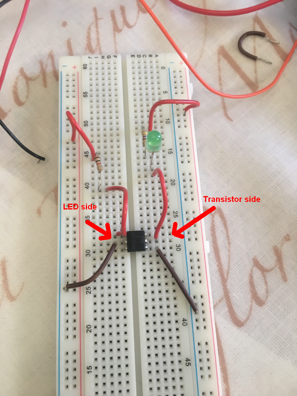
-- So first, we'll just test this out! We will not add the raspberry pi inputs at this test stage, but instead using a battery to supply voltage to LED side of the optoisolator, thus switching on the other circuit! You'll need to calculate what resistor to use depending on the battery you used for the LED side of the optoisolator. Here we can see it working:
-- Now we know the optoisolator works ok. And I think building the circuits in increments like this will help with any troubleshooting, and help with understanding them better!
-- Let's swap that battery on the LED side of the optoisolator for the raspberry pi inputs and outputs. So we are sending the output from raspberry pi GPIO 7 (BOARD numbering) which is 3.3v, and we are sending the 5v from GPIO 2, and we are returning to GND which is GPIO 6 on the raspberry pi.
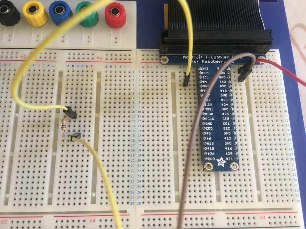
So you can see the GPIO 7 goes to a resistor. That's the 10k Ohm resistor in the circuit diagram above. After that, GPIO 7 goes to the base on the BJT (which I've got on the breadboard shown in image below).
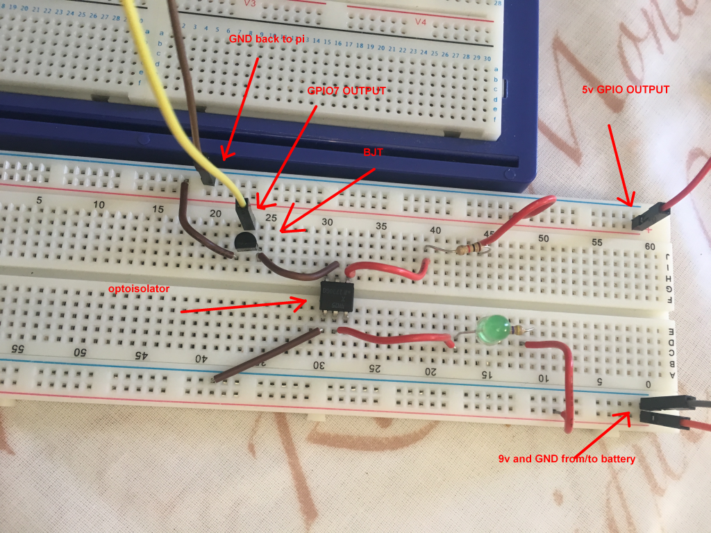
-- Ok, so we are all set to write some code now! And send a voltage from GPIO 7 to the BJT, turning on the LED in the optoisolator, and thus allowing the optically isolated circuit with the green LED to complete! Remember the green LED will be our IR illumination device finally.
import RPi.GPIO as GPIO
import time
GPIO.setmode(GPIO.BOARD)
#GPIO numbering as board
GPIO.setup(7, GPIO.OUT)
#setup 7 for output
GPIO.ouput(7, 1)
# output from 7 is HIGH i.e. 3.3v
print("PIN 7 is output HIGH")
time.sleep(5)
GPIO.output(7, 0)
# output from 7 is LOW i.e. 0v
print("PIN 7 is output LOW")
GPIO.cleanup()
# cleanup
-- Now, let's run it and see what happens! Hopefully the green LED will light up when PIN 7 is high and go off when it is LOW!
-- Great! Well now you should know what is going on, and be all set to connect the IR illumination device instead of the green LED!
Don't forget that you might need different resistors that I did! You can find out how to calculate the resistor you need using Ohm's Law. There are many tutorials if you don't know e.g. http://hades.mech.northwestern.edu/index.php/Resistors_(Ohm's_Law),_Capacitors,_and_Inductors
FINAL CIRCUIT
Well, the final circuit we need to switch on the IR illumination device is quite similar to the above! We replace the 9v battery with a 12v lead acid battery, and the LED is replaced by the IR illumination device! We also alter our resistors! Don't use the 220 Ohm with the 12v IR illumination device!
[show it here]
Discussions
Become a Hackaday.io Member
Create an account to leave a comment. Already have an account? Log In.