alexw
alexw-
Third generation hardware update
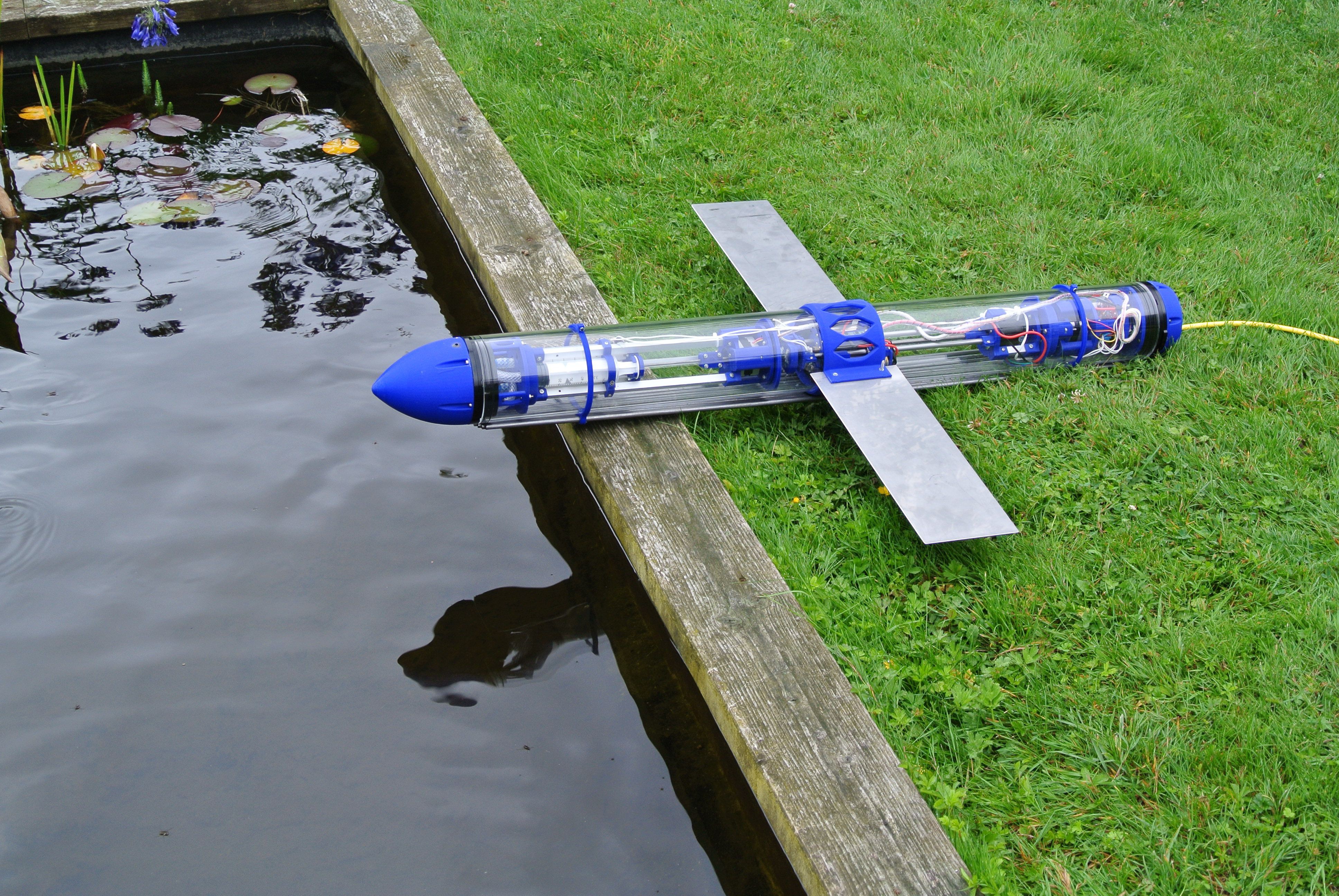
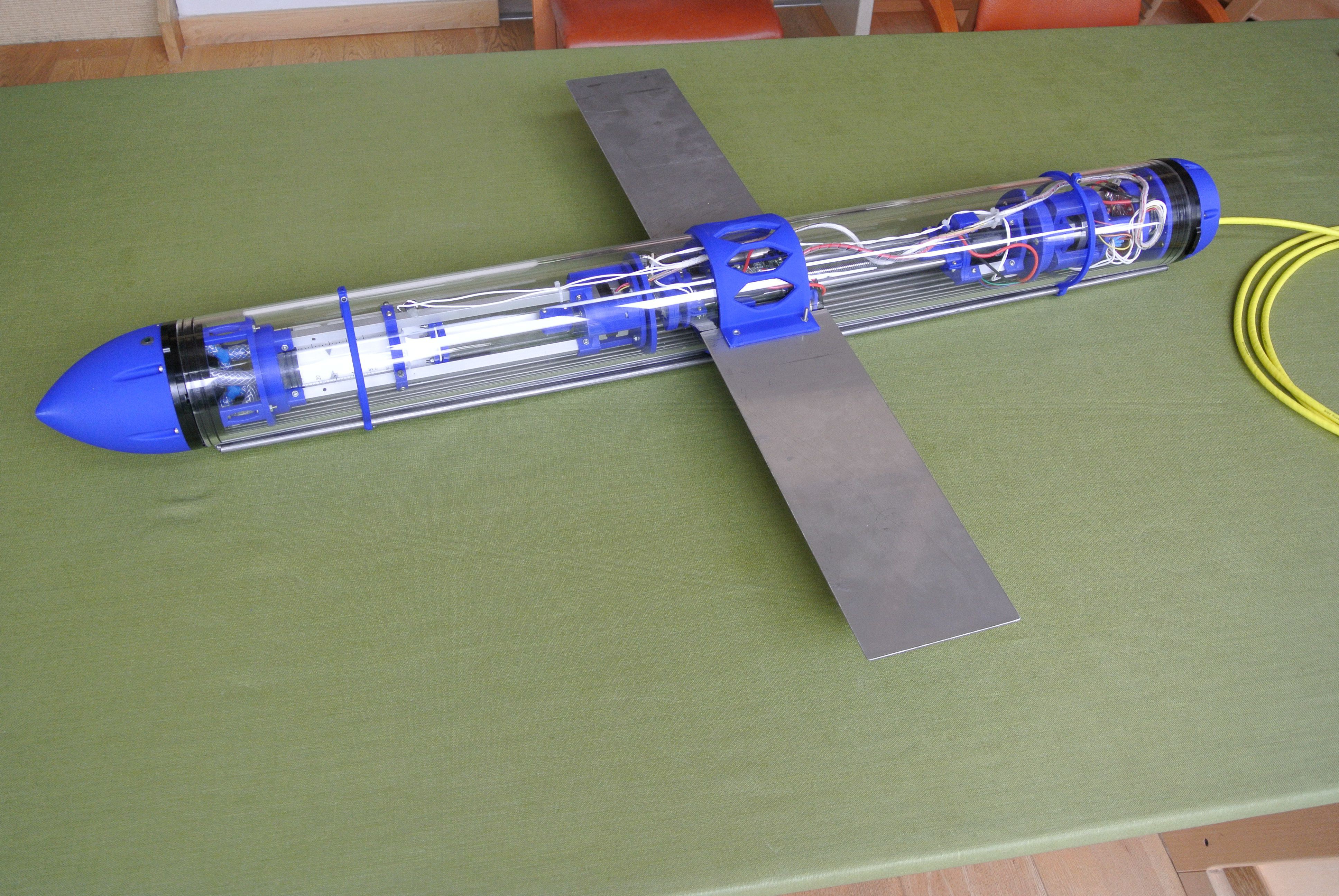
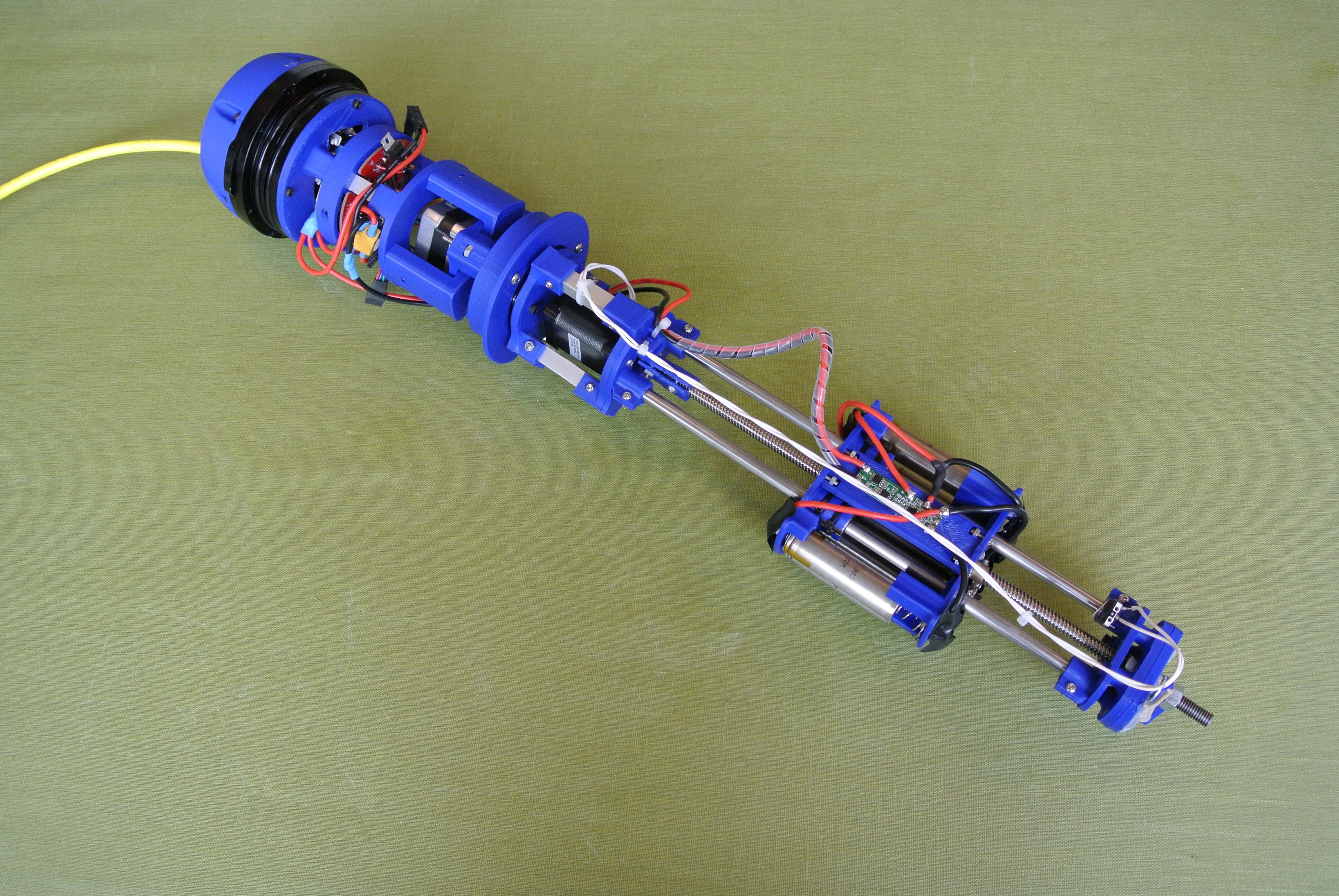
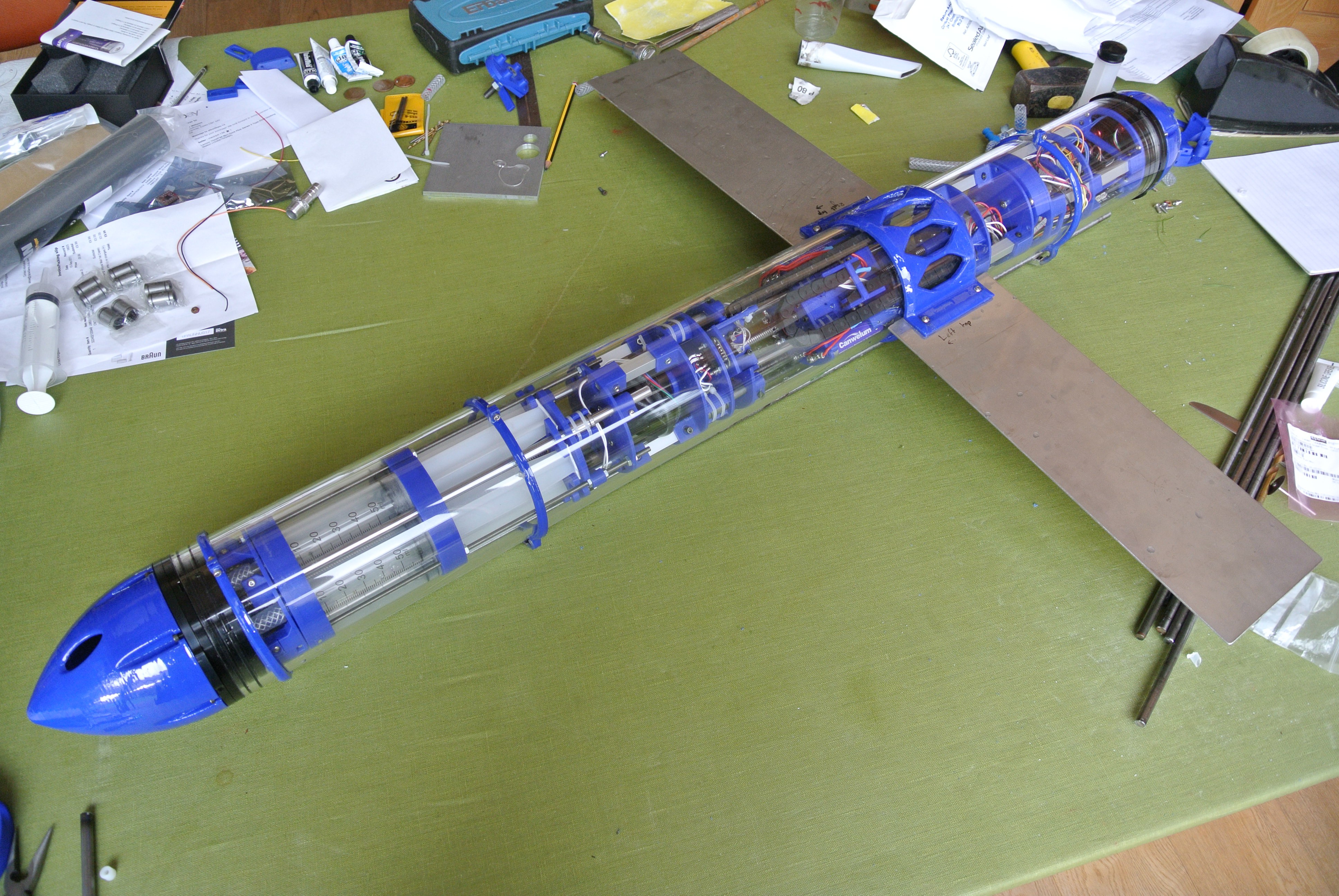
09/19/2017 at 17:09 • 2 comments![]() This week I have more or less finished the design of the third generation of the glider. I have printed all of the parts and assembled the glider. A couple of notable design changes include the larger buoyancy engine (390ml vs 150ml), quicker buoyancy engine displacement change (~6 seconds vs ~30 seconds) and various cable management improvements (e.g. pogo pins to connect the electronics of the front/back and cable chains).
This week I have more or less finished the design of the third generation of the glider. I have printed all of the parts and assembled the glider. A couple of notable design changes include the larger buoyancy engine (390ml vs 150ml), quicker buoyancy engine displacement change (~6 seconds vs ~30 seconds) and various cable management improvements (e.g. pogo pins to connect the electronics of the front/back and cable chains).Whilst assembling, some of the parts required post processing, so I will work through the Onshape document updating all the parts with the minor changes and bar/wing mounts (I used second generation mounts as this was quicker). I also photographed the majority of the build so will be able to produce detailed build instructions.
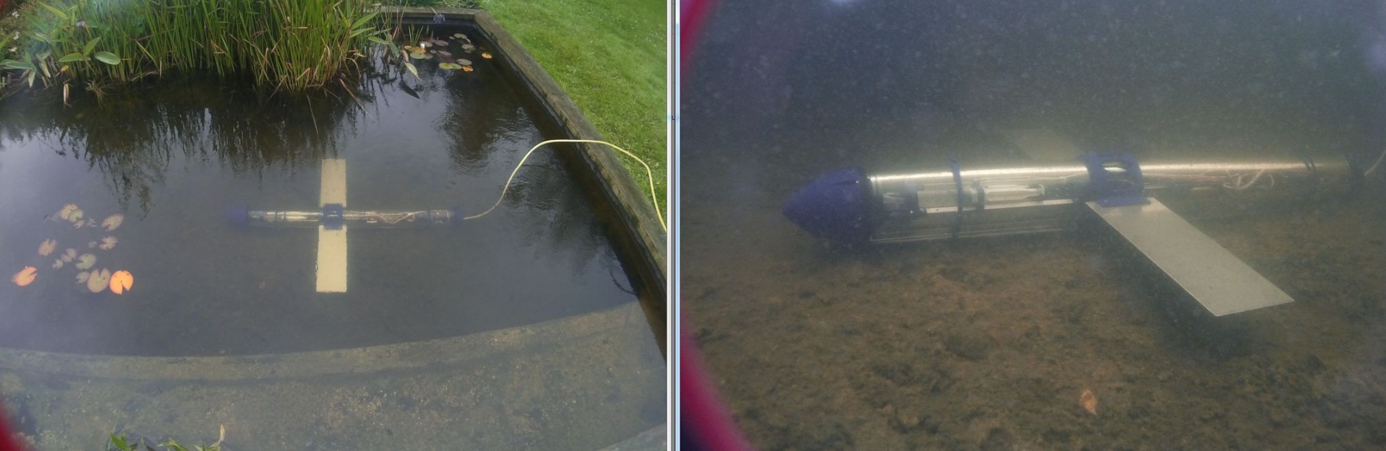
A quick video demonstrating the newer glider is below:
This video is a relatively poor representation of the gliding capabilities of the glider currently as it is still changing pitch when it touches the bottom of the pond (if descending) and vice versa, so it could well reach an angle of attack which would cause it to stall, if the water were deeper. A deeper section of water is required to test the newer hardware more thoroughly.
As stated, the components will be updated, but the current hardware set can be found at Onshape and the program that the glider is running during the video is on the GitHub page.
![]()
-
Functional peristaltic pump and why I’m not using it
09/03/2017 at 18:35 • 6 commentstl;dr : Parameterised and printed a few peristaltic pumps and then designed my own peristaltic pump but they require too much torque to function with the stepper motors. Staying with a syringe design design for version 3 of the glider and will re-explore peristaltic pumps at a later date.
Over the last few weeks I have been working on a peristaltic pump to act as a buoyancy engine. The advantages of a buoyancy engine is that it allows for a greater variable ballast within a more compact frame than the three syringe buoyancy engine that I am currently using.
I had a look for existing printed peristaltic pump designs and I came across a parametric planetary gearbox peristaltic pump. This design was a derivative of a parametric planetary gearbox, which I was considering for the planetary gearbox for the roll mechanism as it allows people to print a gearbox with tolerances that have been adjusted for their printer. Editing the openSCAD file allowed for the addition of a motor mount and a custom exterior, allowing it to be integrated into the glider design (mounting/wiring holes). The openSCAD file is available in the developmental dropbox folder (Glider_version_3/SCAD_files) if you want to take a look/try printing it yourself.
![]()
The first version of the planetary gearbox peristaltic pump did not work there was not enough of a gap for the peristaltic tubing to get into position and for the gears to turn. I printed a few more peristaltic pumps, changing the settings each time, but they all had issues with tolerances; if the gears are too close together, they will come out of the printer bonded together; if the gears are too far apart, there is play in the system. If there is too much play in the gearbox the amount of “squish” that the peristaltic tubing undergoes varies as the gears rotate, therefore the pump may be sealed at a certain rotation, and will hold pressure, but at another position, the tubing will be less compressed and a pressure differential cannot be maintained. Having said this, the mechanism is very pleasing and a great demonstration of the capabilities of 3D printing:
As the planetary gearbox has herringbone gears, it is not possible for you to disassemble/assemble the gearbox, consequently it has to be printed as a whole piece, which takes ~8 hours. The slow print times meant that this was hard to iterate more than once a day, slowing development. Therefore if the peristaltic pump was redesigned to be composed of multiple parts and then assembled, you could alter individual parts and reprint single pieces (as opposed to the whole pump), reducing the time between iterations, making the development of the pump quicker. Even if I had been able to produce a version of the planetary gear pump that worked reliably, it took a long time to dial the settings in, it would not have been a viable choice for the glider as it is not easily reproducible.
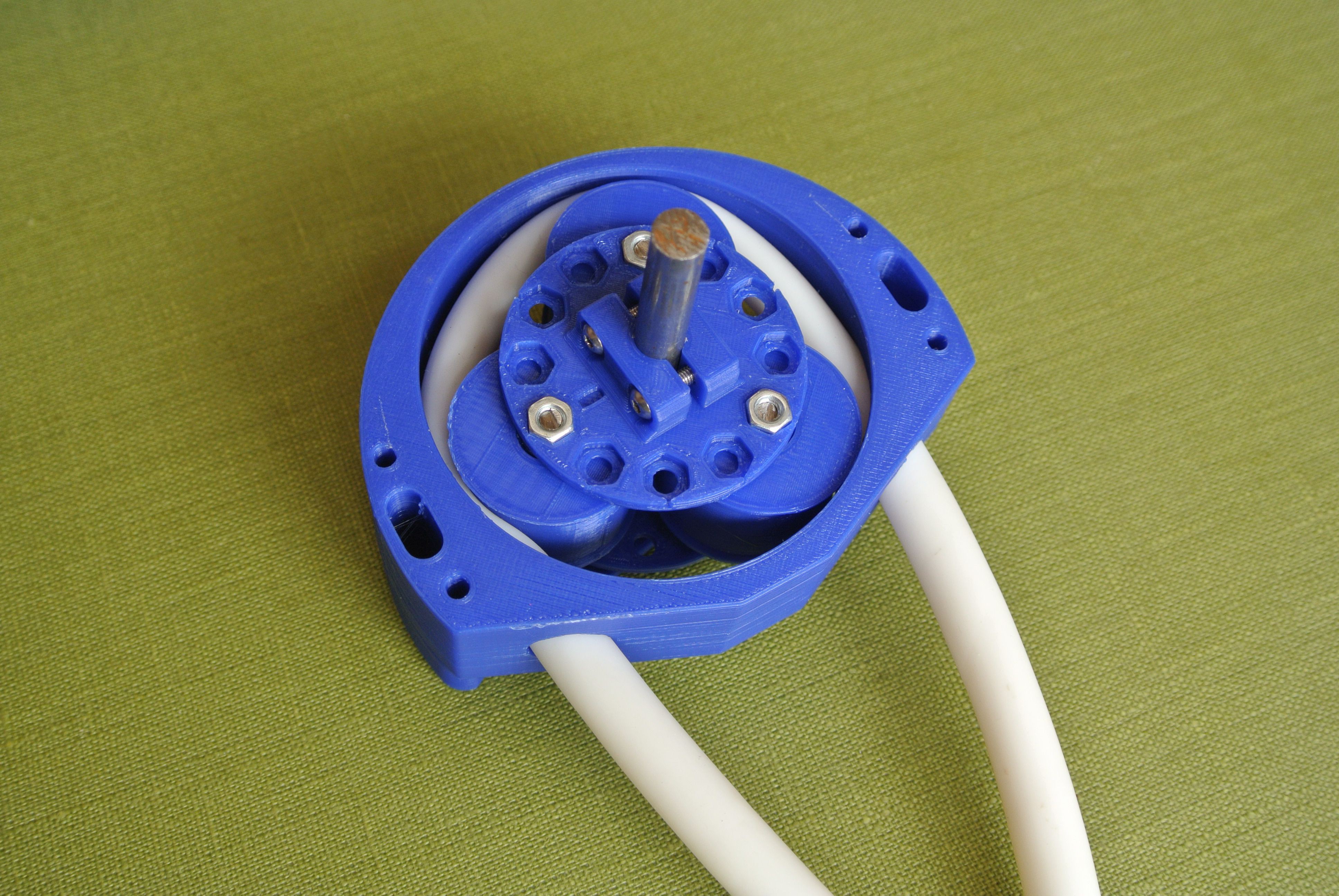
I produced a set of peristaltic pump parts within the Onshape glider document and assembled them within an Onshape assembly to check dimensions without printing. I also made the parts capable of putting the rollers at different positions, reducing revision time (disassemble/reassemble with rollers in different position vs redesign/reprint/disassemble/fit new parts).
![]()
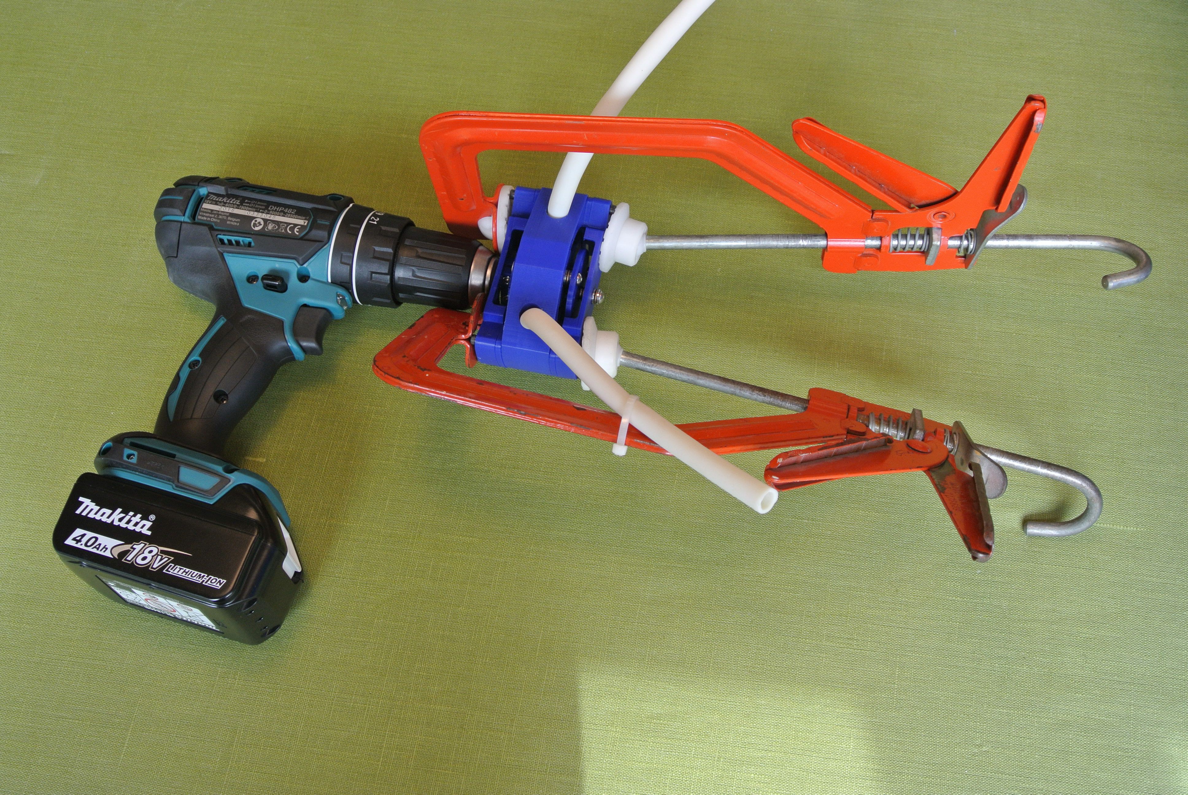
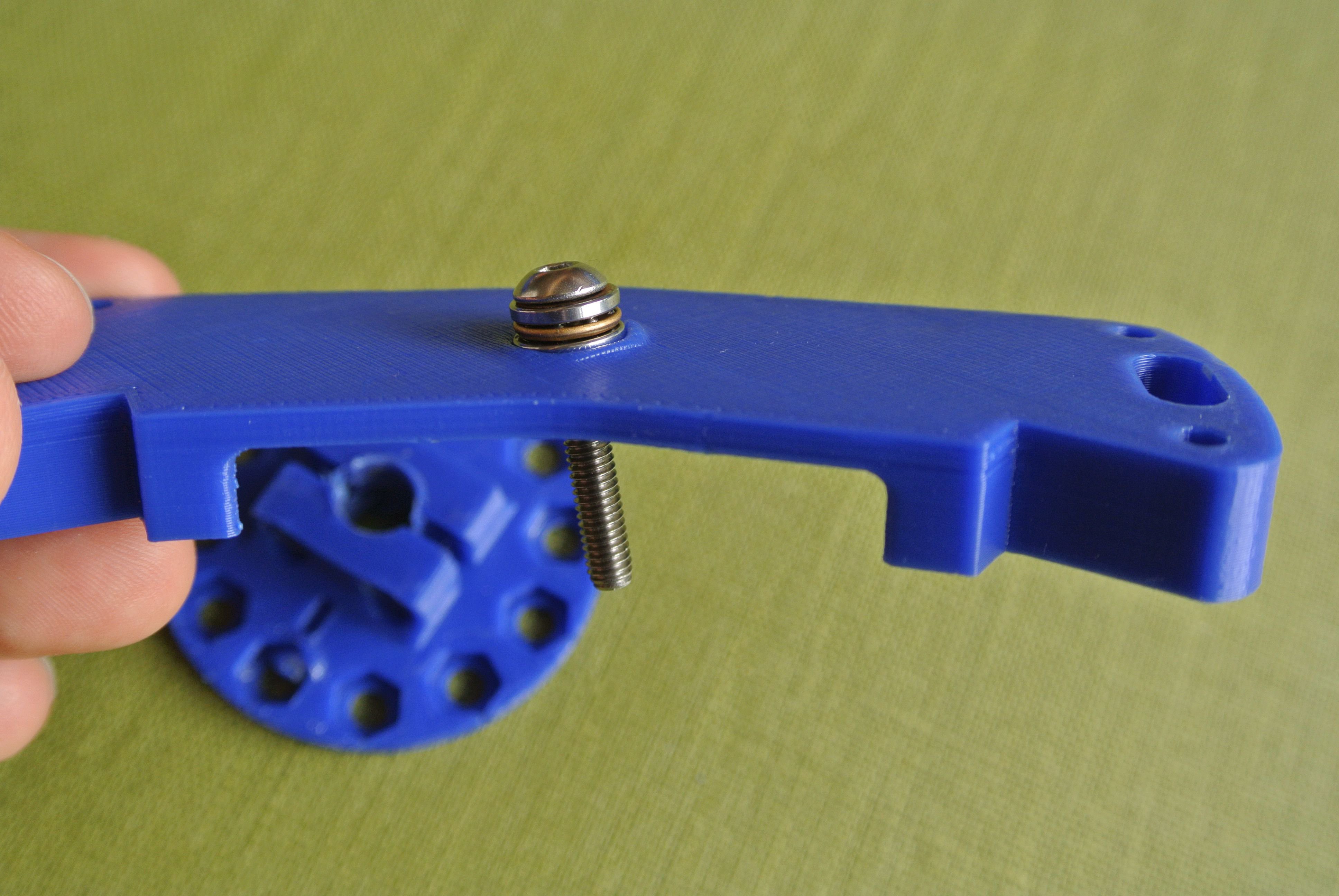
This new design was able to close the tubing but required more torque than the stepper motors were able to supply. I was able to run the peristaltic pump with a drill, as this had sufficient torque. (The clamps seen in the image below are because I do not have M3 bolts long enough to hand)
![]()
I did some initial experimentation, but ran the pump a little too hard (seeing how far it could squirt water – the limit was about 1.5m) and this caused friction to cause the printed parts to heat and deform under the stresses, rendering the pump useless.
![]()
Unfortunately, I didn’t take any footage of this initial testing so I decided to reprint the pump to take footage and do more testing (all at a much lower speed) The pump was able to work quite effectively (skip to ~0:30 to see it working quickly).
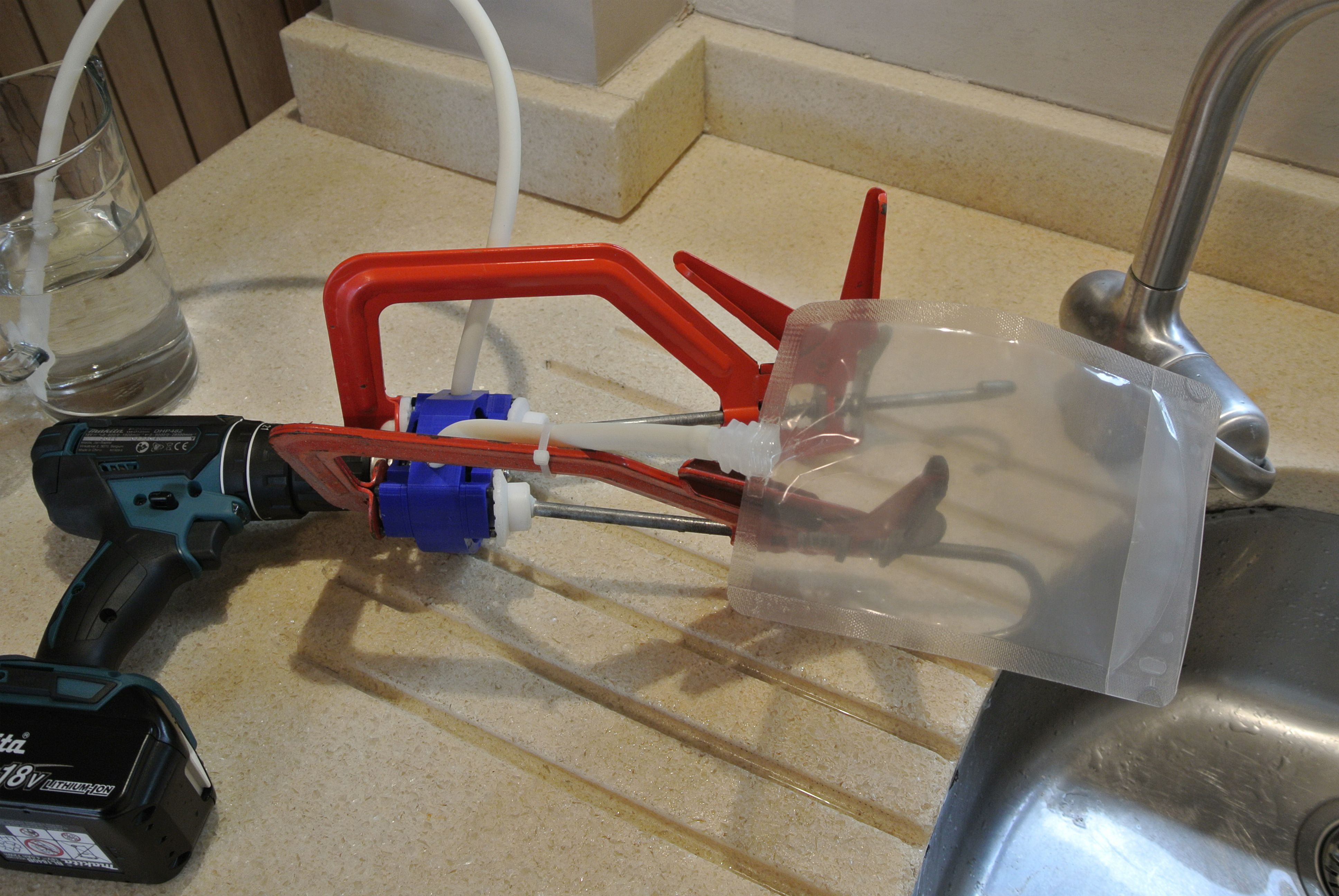
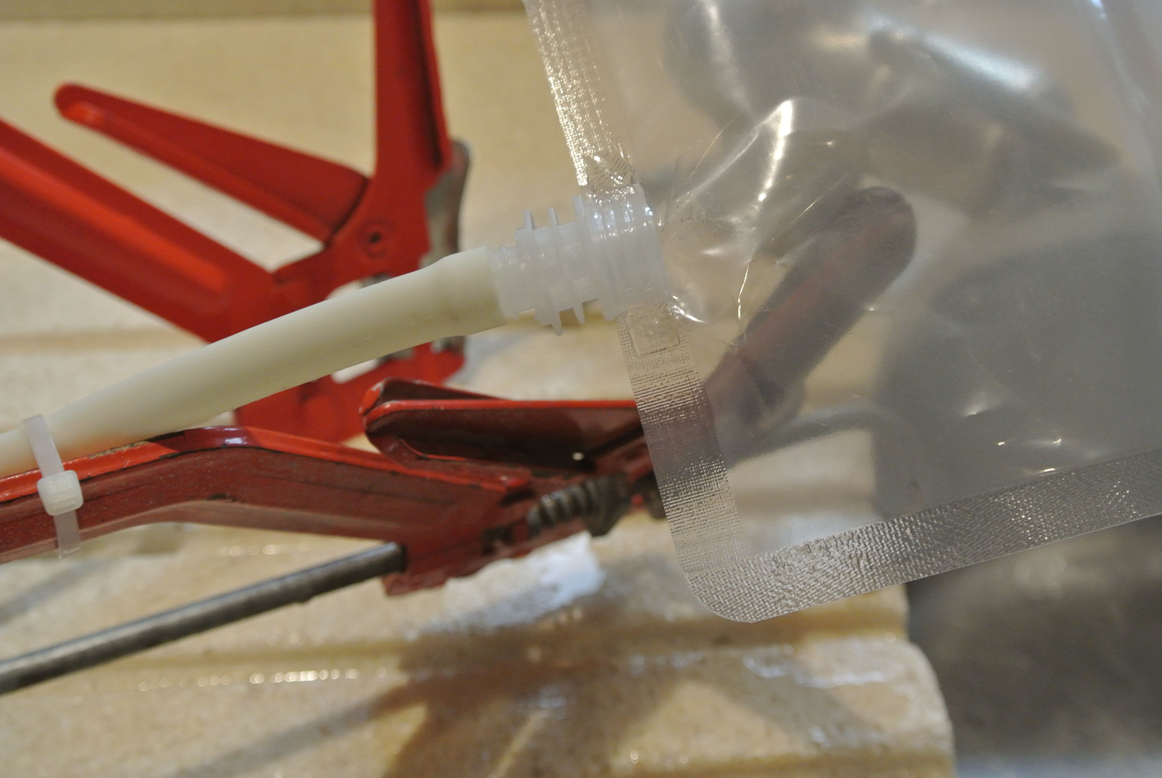
A buoyancy engine for the glider using a peristaltic pump would transfer oil/water between two bladders. I used a drinks pouch as the bladder in this case for testing (You can purchase mylar drinks pouches rated to a pressure of 4 bar).
![]()
![]()
The first test with the bladder was to fill it with water and to deplete it. Demonstrating that the pump is able to extract all the liquid from the bladder.
I also performed a test with the bladder where I pressurised the bladder with air and squeezed it, seeing if the bladder/pump is capable of maintaining a pressure differential. I did not notice a decrease in pressure.
Although I have spent a long time on the pump and have been able to produce a functional pump, I will not be using it for the third version of the glider. The primary reason for this is the torque requirement, but there are other minor reasons for not using the pump; it would be non-trivial to produce a reliable endstop for a bladder; the bladder is not as widely available as syringes etc.. I have been able to use Onshape’s version control to branch the design so I can come back to the peristaltic pump at a later date.
![]()
-
PCBs have arrived
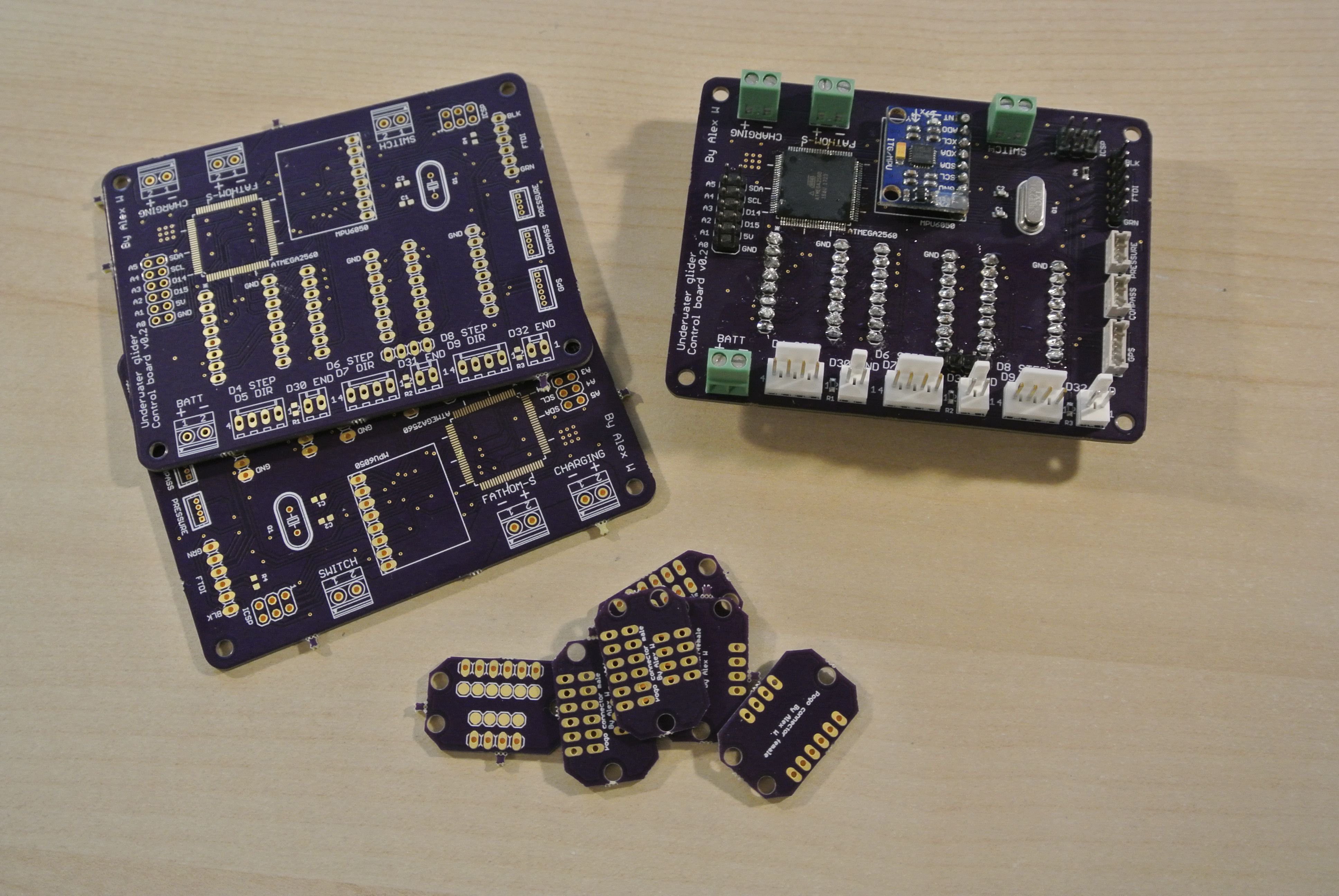
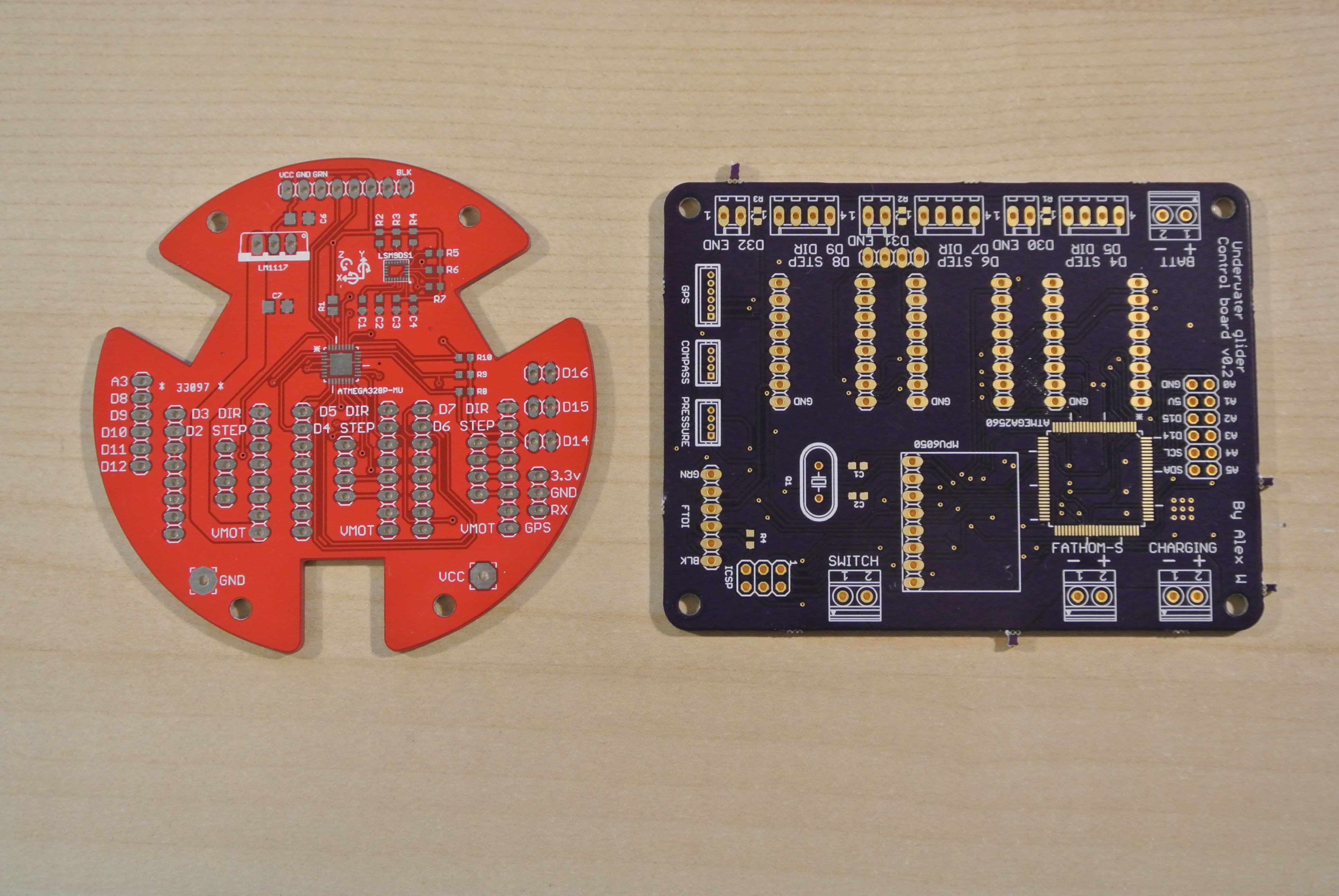
08/23/2017 at 15:21 • 1 commentThe PCBs have arrived from OSHpark (I was impressed at how quick they were, 9 days to the UK with the super swift service and super saver delivery) and are the very high quality you would expect with OSH park.
![]()
Population of the board was relatively straightforward; there are a couple of SMD components and the majority of the other components are through hole headers (this version of the control board is a glorified breakout board). The new control board is only a little bit larger than the previous version, but will be mounted horizontally as opposed to vertically.
![]()
I have also designed a mount to attach the Fathom-S board to the control board.
![]()
The Fathom-S board mount can be exported from the Onshape CAD model (right click on a part and select "Export" to download the STL of a part)
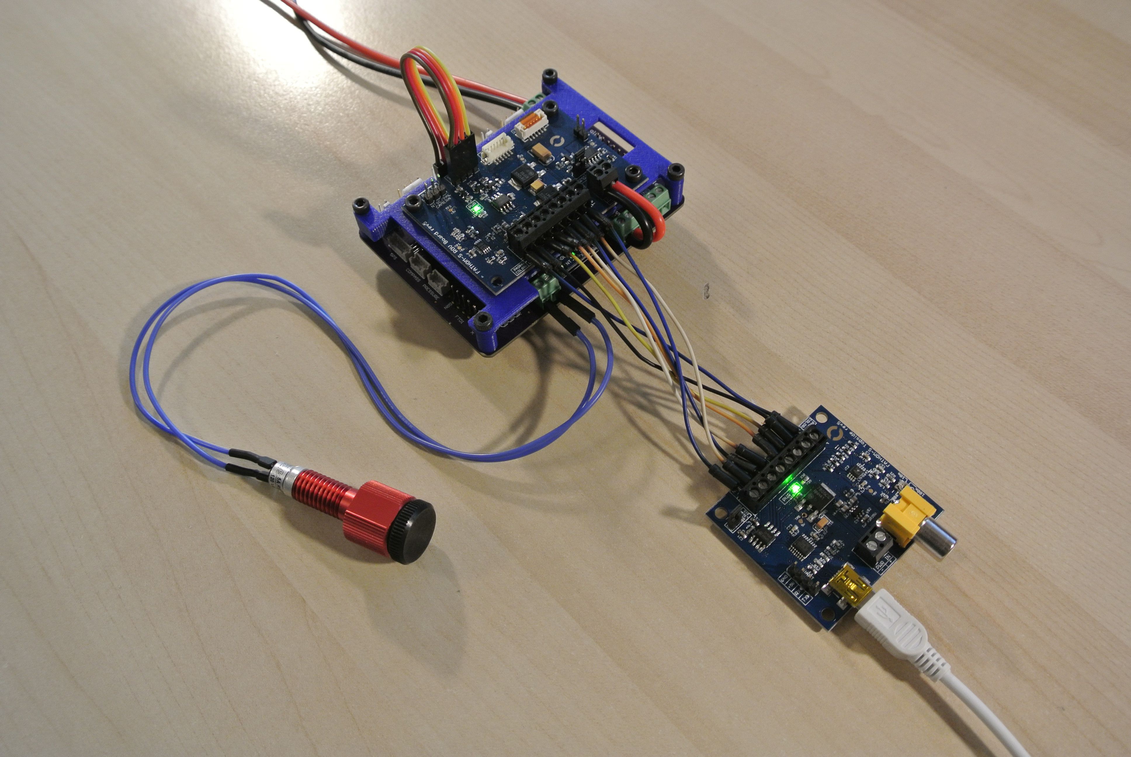
There is a error whilst uploading to the control board via the FTDI header ("avrdude: stk500v2_ReceiveMessage(): timeout"), but programming via the Fathom-S boards is fully functioning. (the 8 wires connecting the two Fathom-S boards can be replaced with up to 600+ metres of Fathom cabling)
![]()
When programming over the Fathom-S boards, the glider's boards will only power on if the USB is attached to the topside board. However, if not programming, the boards can also run standalone off of batter power. I plan on using a Bulgin Standard Series buccaneer connector so that you can disconnect the Fathom cabling, making this feature is very useful.
![]()
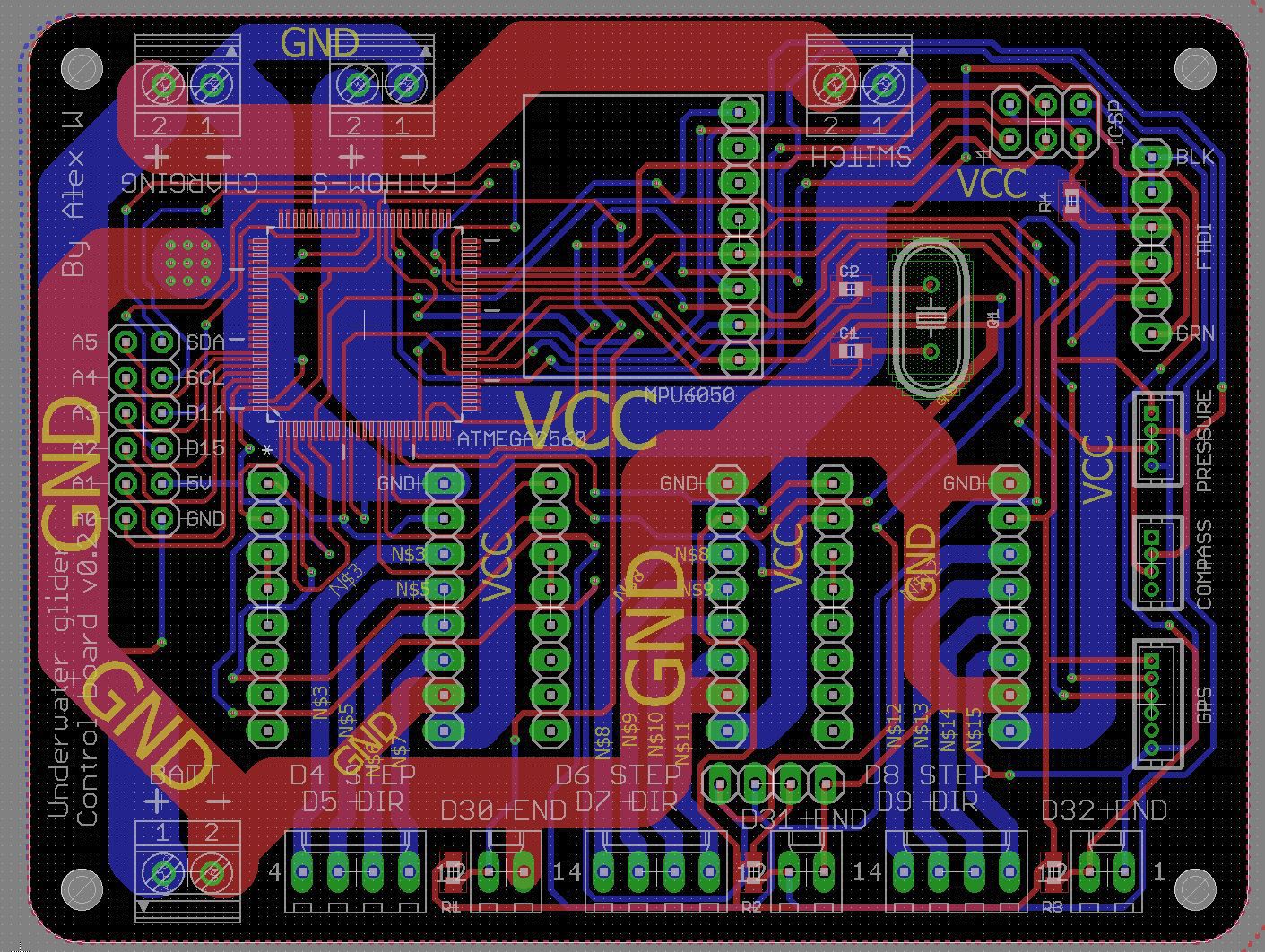
After attaching the Fathom-S board, I made a couple of changes to the control board (moving a couple of headers a millimeter or two and changing the silkscreens a little to make them more useful/clear) The latest board version is v0.2.1 and can be found in the development folder on Dropbox (Glider_PCBs/Control_board/v0.2.1). As with version v0.2, there is an error when uploading the .brd file to OSH Park (related to the SMD capacitors; remove them and it works, add them from the default rcl library and it breaks, I have no idea what is going on), so a zip folder containing all the gerber files is also found within the Dropbox folder.
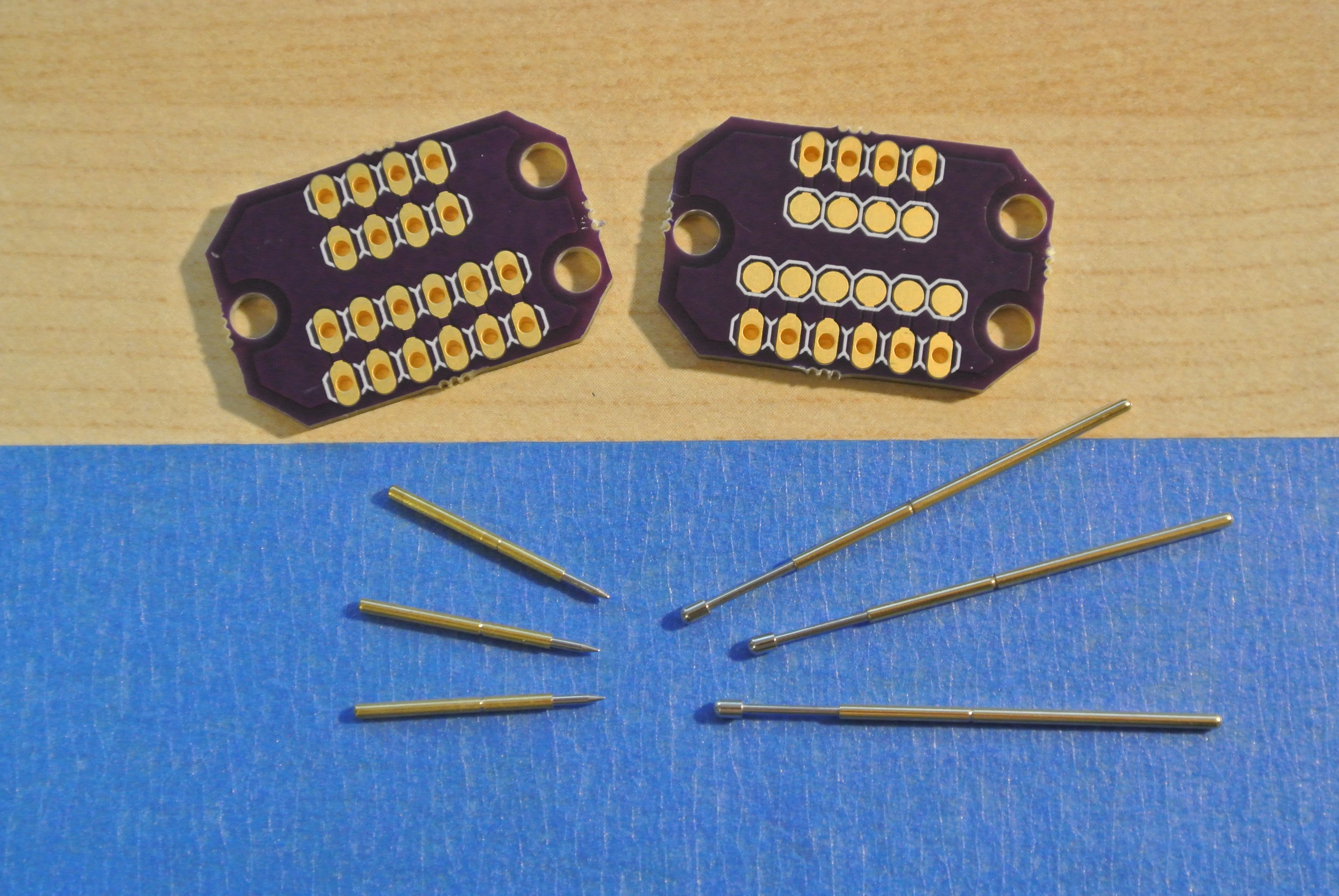
I also ordered a couple of PCBs to help with cable management. On the second generation glider, there was a set of cables running from the buoyancy engine (stepper motor/endstop wiring) that had to be plugged into the control board, but this would be hard to plug in and slack would occur in the wiring, interfering with the movement of the mass assembly. To fix this, I produced a pair of PCBs, one for the front end of the glider and one for the back. When the back end is slid into the tubing, pogo pins would touch against the pads on the front end PCB. One potential issue with this design is that the two PCBs will have to be within a couple of millimeters of their required positions, as the pogo pins do not compress much (2mm). Moreover, the blue robotics tubing can vary by ±3mm, so the user must be able to set the PCB positions themselves.
![]()
The two PCBs are both within the Dropbox folder: Glider_PCBs/Buoyancy_engine_connector_female and Glider_PCBs/Buoyancy_engine_connector_male.
-
PCB development
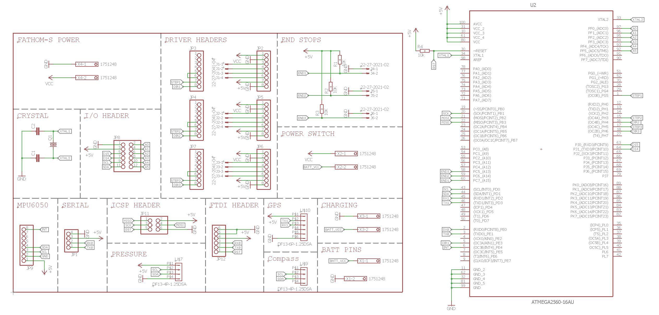
08/15/2017 at 20:24 • 1 commentI realised that the production of PCBs will take a couple of weeks, so I have prioritised the redesign of the PCBs over the last few days. This version of the PCB is designed to work in conjunction with the Fathom-S tether interface from Blue Robotics. The control board uses the serial output from the Fathom-S to program the control board and allows for remote communication. The Fathom-S board provides a serial port connection over a tether length of 600+ metres, compared to the glider's current 5 metre limit (USB communication limit). Additionally, the control board passes through the battery supply to the Fathom-S so that the control board uses the 5V supply that the Fathom-S board produces with its 7805 regulator. Programming the control board via the Fathom-S interface requires a dedicated serial port, so in order to use another serial device (compass or dissolved oxygen sensor) more dedicated serial ports are required. Therefore I am now using an ATMEGA2560 as opposed to the ATMEGA328P, providing up to 4 UART connections (and much more flash memory; 256kB compared to 32kB). Other changes include a dedicated 16MHz crystal and using the MPU6050 breakout board as opposed to the LSM9DS0 (Still out of stock until November).
Although this control board can be used as a standalone autopilot, with the MPU6050 and external pressure sensor/compass/GPS, the board can also be used as a slave board for an external autopilot (such as Pixhawk). To allow this, there is a set of header pins towards the left of the board for analog inputs/digital outputs. The control board reads PWM signals through the analog pins from the external autopilot and converts the signal into absolute positions for the motors.
Although I am aware that KiCad is more open-source and is completely free (no paid for features, therefore more accessible), I have decided to stick with Eagle. Given time restraints, it is practical for me to continue using a program I am familiar with. (Onshape was quick to pick up as it is very similar to Solidworks)
Images of the schematic and board are below and you can download the Eagle design files from the Dropbox development folder (Glider_PCBs/Control_board/v0.2). I have ordered the control board from OSH Park with their Super Swift service and paid for postage to the UK so the boards should be here in about a weeks time.
![]()
![]()
-
Designing third generation hardware
08/05/2017 at 21:21 • 0 commentsI am using the cloud CAD service ‘Onshape’ to produce the model of the third generation of the glider. This allows the design to be more open (all files are public and viewable at any stage during the design process) and more accessible (Onshape is free and does not require an expensive license, only an internet connection).
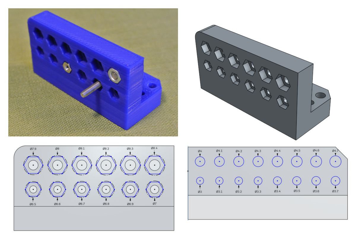
I'm going to produce parametric parts with dimensions that vary in accordance to local variables. The third generation of the glider will be designed so that the user can input values according to a test print and then all dimensions of the printed components would be adapted for the user’s printer, which would minimise post processing. Unfortunately Onshape does not let you specify global variables, (values that remain constant between different parts within an assembly), so I will design the glider within a single “Part studio” (A multipart assembly). If this is too complex (too many features in a single file), I will have to remove the parametric feature.
An example test piece is below and shows how a single piece would be able to determine the best values for a person's printer for dimensions such as the size of a hole for an M3 bolt through a wall.
![]()
A live version of the glider model can be found here and is updated automatically whenever I make an edit to the model.
-
Underwater gliding
08/02/2017 at 09:55 • 5 commentsI have been able to use a pool to test the glider and although there was not a lot of video footage, it provided a lot of information about how well the glider currently works and any flaws that the current design has.
The below video only shows the descent phase as the buoyancy engine was not working reliably enough at this point to demonstrate the transition between descent and ascent. Also, the IMU has yet to be integrated into the control software, so the glider does not have a PID algorithm to adjust the position of the mass; you can see that the mass does not move from its fixed position at the front of the rail. As the mass is at the front of the rail, the glider’s angle of attack is high so the glider’s glide ratio is quite low.
The exterior printed parts would fill with water through very small imperfections, this caused the glider’s ballast trim to become incorrect over time (to the extent that the glider was unable to become positively buoyant at all). I will tackle this by reprinting the parts with a 100% infill, so water would be unable to enter the prints.
Also, when the engine motor has insufficient torque to drive the plungers, the plungers will jam with the rotor still rotating. This causes the nut to dig into the drive screw and the nut wears away the thread. This then causes the plungers to jam more frequently. A peristaltic pump would potentially address this issue. I plan to design a peristaltic pump proof of concept within a couple of weeks.
-
PCB modifications
07/24/2017 at 13:44 • 0 commentsSeveral modifications to the control board PCB have been made.
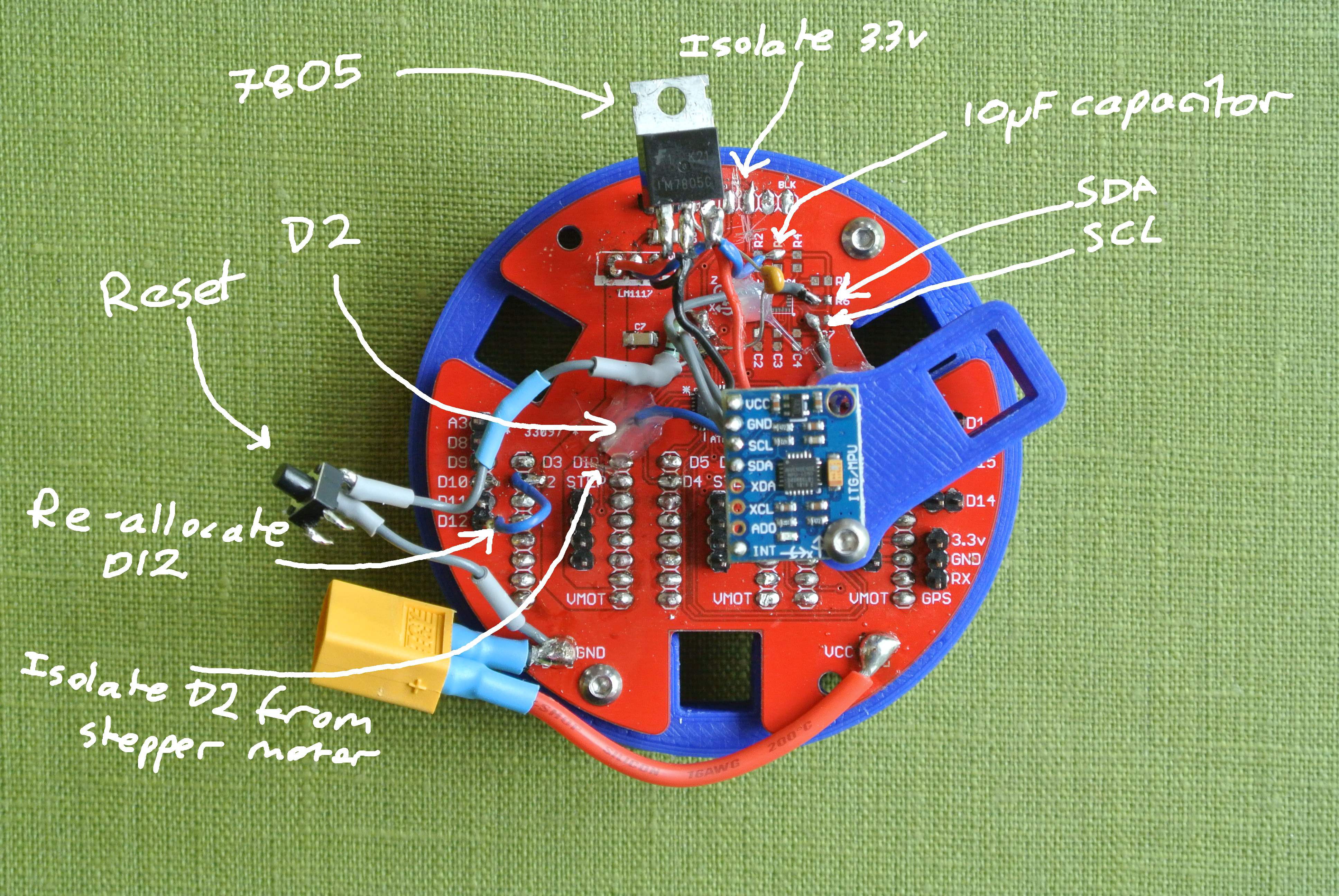
![]() As the IMU that I was going to use (LSM9DS1) is out of stock until November, I had to modify the board to use an alternative IMU (MPU6050), which does not have a magnetometer. I used the SDA and SCL pads from the board to hookup the MPU6050. I had also set digital pin 2 on the atmega328p to control a stepper motor, however the MPU6050 requires the digital pin 2 specifically, so you can scrape away at the PCB to obtain the D2’s signal track, making sure to isolate the D2 signal from the stepper motor. You have to re-allocate D12 (or any other spare pin apart from D10 - used during program upload so can cause erratic behaviour) to the “Step” pin of the left hand stepper motor driver.
As the IMU that I was going to use (LSM9DS1) is out of stock until November, I had to modify the board to use an alternative IMU (MPU6050), which does not have a magnetometer. I used the SDA and SCL pads from the board to hookup the MPU6050. I had also set digital pin 2 on the atmega328p to control a stepper motor, however the MPU6050 requires the digital pin 2 specifically, so you can scrape away at the PCB to obtain the D2’s signal track, making sure to isolate the D2 signal from the stepper motor. You have to re-allocate D12 (or any other spare pin apart from D10 - used during program upload so can cause erratic behaviour) to the “Step” pin of the left hand stepper motor driver.The 3.3v regulator was swapped out for the 7805 5v regulator, as the MPU6050 requires a 5v supply. The pinout of the 7805 is different to the original regulator, so be careful when swapping the regulators. The 3.3v from the FTDI cable will also have to be isolated, meaning you cannot power the Atmega328p by only the FTDI cable, you also require external/battery power. I will add an automatic power supply switching circuit for the board by the next board revision.
To enable auto-reset when uploading, a 10uF ceramic capacitor was linked between DTR/RTS pin of the FTDI cable/adapter.
Although not as necessary, I also added a reset button.
I hope to produce another revision of the board with these alterations soon.
-
Underwater testing
07/24/2017 at 13:40 • 3 commentsAs the design is at a stage where it is watertight and all motor controls are working, we were able to test the glider underwater.
The first clip is of the glider ascending as the buoyancy engine expelling water. The air bubbles released at the start is air coming out of the nosecone as it fills with water. The second clip is an underwater view of the glider as it descends by taking water into the buoyancy engine.
During underwater shot, you can see my fingers nudge the glider downwards slightly, this is only to prevent the nosecone from breaking the surface of the water as the nosecone will take in a small amount of air which will become trapped and prevent the glider from descending.
![]()
![]()
We need a larger (and deeper) volume of water in order to trim the glider properly and to test forward motion.
I intend for the third version of the glider to be documented to a greater depth so you can print and assemble the glider. You can produce the first generation of the glider using the information/files I have provided on Hackaday, and in order to produce the second generation, you can obtain the STL files from the development dropbox folder.
-
Second generation glider completed
07/24/2017 at 10:39 • 0 commentsWhilst the first generation of the glider was beneficial as a design concept, it was not designed to be functional (there was design flaws which prevented it from being watertight etc)
The second version of the glider has been completed, this version builds upon the first generation using the general structure but adapts it for a larger tubing whilst ensuring it is watertight. (Although this version of the glider is functioning, it looks less good than the first generation)
The endstops are now implemented and here is a short demonstration of the glider homing itself once turned on, without an external power source:
The control software for the homing of the glider can be found in the GitHub repository along with a python script that allows the user to control the glider via key presses. The python script first initialises a connection with the glider using the serial port, then it uses the tkinter library to detect key presses and sends the command across the serial port. The arduino detects these and moves the servos as requested. This allows for a more streamlined interface with the glider compared to the Arduino serial monitor.
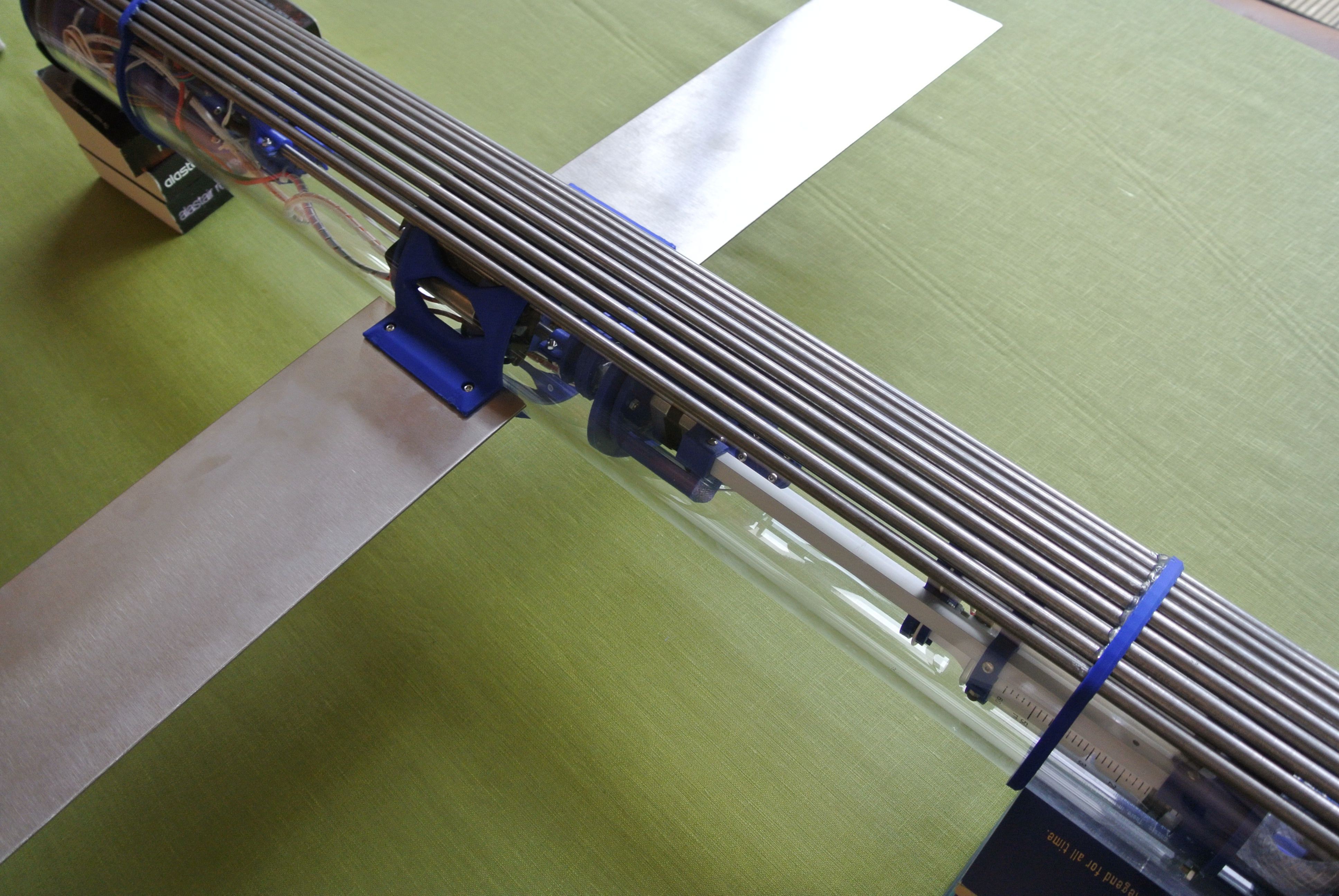
The original printed wings have been replaced with stainless steel wings as I did not originally understand the hydrodynamics of the wings. An additional benefit is that the steel wings are heavier and so act as ballast.
![]()
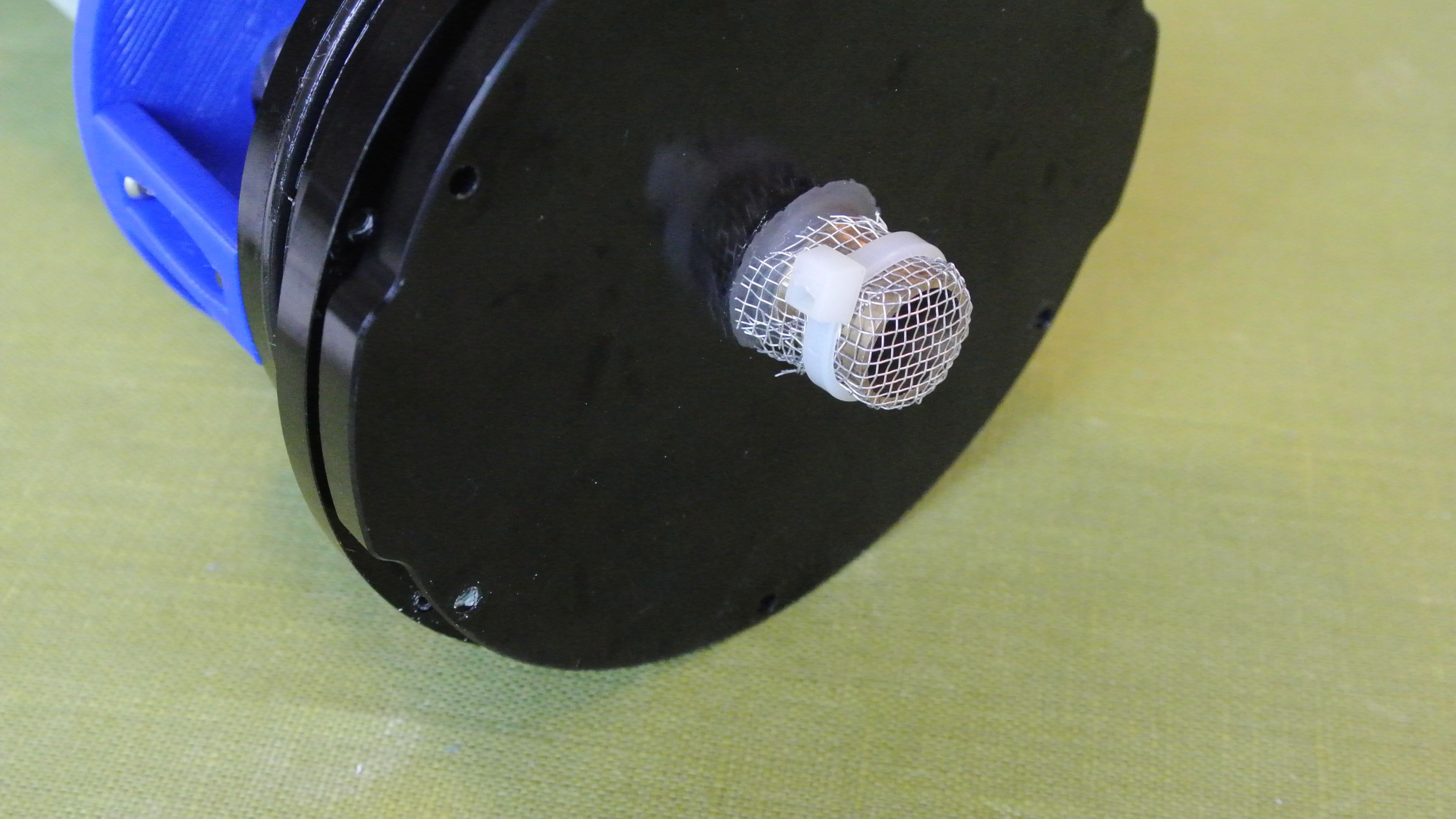
A nosecone was printed for the frontend to streamline the glider slightly. The nosecone bolts onto the front endcap, after the endplate, so the nosecone does not need to be watertight. A piece of gauze was added to the water inlet to minimise fouling.
![]()
![]()
The batteries have been hooked up to the control board and the glider is able to run without external power. The batteries charge through the communication/power cable and the battery protection circuit prevents overcharging/overdischarging/shorting etc.
![]()
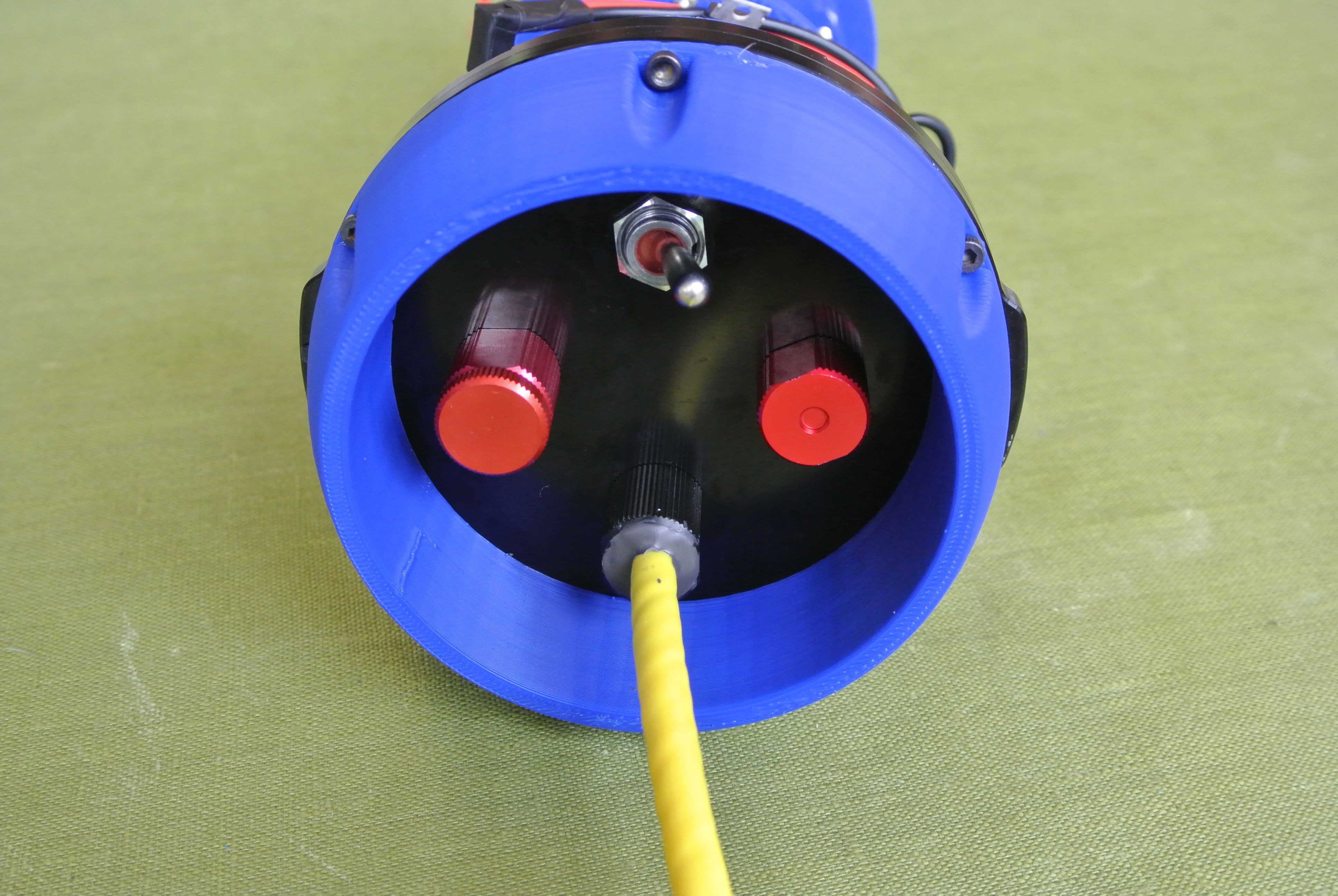
The back endcap has a pressure equalisation inlet, power switch, communication/power cable and a blank (will be replaced with a pressure sensor), A printed shroud was added to protect the connectors on the endcap (and to prevent something from turning off power to the glider).
![]()
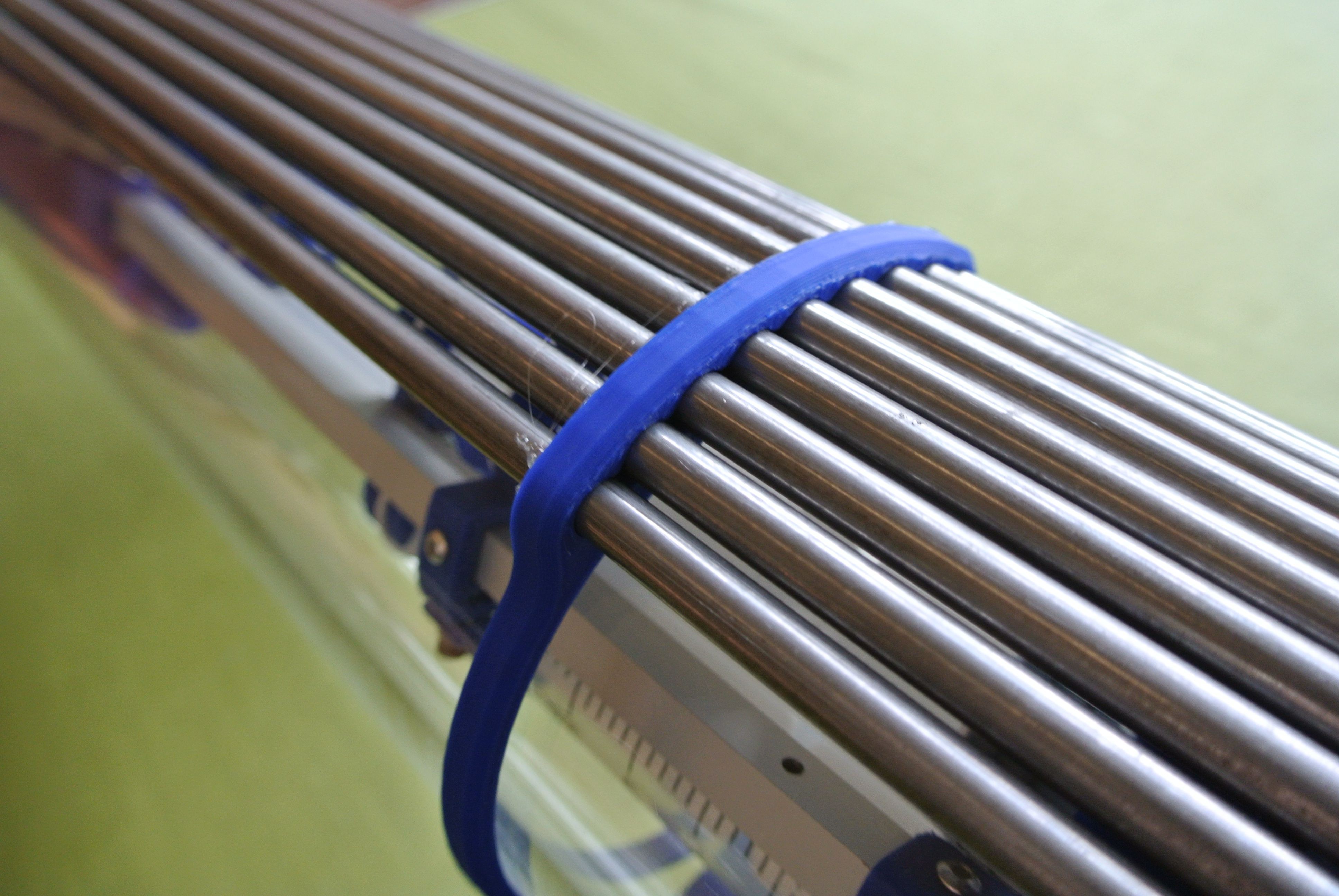
Mild steel rods were used on the underside of the glider to act as ballast and will be used to trim the glider so that it is neutrally buoyant when the buoyancy engine is half full.
![]()
![]()
-
Glider simulation using Unity3d
07/22/2017 at 21:57 • 7 commentsWe want to develop the control software for the glider in a way that will allow testing. In theory, with an accurate glider model, this allows you to develop the software independent of hardware, reducing the cost/time of PID optimisation.
The control software sets the buoyancy and trim and requests the angle and depth. Therefore, the Arduino code is written so that it either controls real or simulated hardware. A compiler flag is used to switch between real or simulated hardware.
Using Unity3d I created a simulation of the glider ascending/descending. The movement through the "water" is modelled using the buoyancy engine, Realistic Water Physics. The glider is modelled as a number of elements, the main body, a volume at the front that changes buoyancy and a mass that moves on the underside of the body that trims the angle.
Unity provides an Arduino with depth/gyroscope readings which are then used by the Arduino to calculate motor movements and these are passed back to Unity. Using these motor movements, Unity models the simulated glider.
The below GIF shows a screen capture of the glider simulation ascending and then descending.
![]()
Over the coming weeks I will optimise the simulation model to accurately reflect experimental data from the glider.
OSUG: Open-Source Underwater Glider
A versatile autonomous environmental drone using a buoyancy engine
 This week I have more or less finished the design of the third generation of the glider. I have printed all of the parts and assembled the glider. A couple of notable design changes include the larger buoyancy engine (390ml vs 150ml), quicker buoyancy engine displacement change (~6 seconds vs ~30 seconds) and various cable management improvements (e.g. pogo pins to connect the electronics of the front/back and cable chains).


 As the IMU that I was going to use (LSM9DS1) is out of stock until November, I had to modify the board to use an alternative IMU (MPU6050), which does not have a magnetometer. I used the SDA and SCL pads from the board to hookup the MPU6050. I had also set digital pin 2 on the atmega328p to control a stepper motor, however the MPU6050 requires the digital pin 2 specifically, so you can scrape away at the PCB to obtain the D2’s signal track, making sure to isolate the D2 signal from the stepper motor. You have to re-allocate D12 (or any other spare pin apart from D10 - used during program upload so can cause erratic behaviour) to the “Step” pin of the left hand stepper motor driver.