 Peter McCloud
THE LATEST VERSION OF THIS PROJECT IS AT
#Electric Variable Pitch Rotor Mk. II
Background
Multi-rotor vehicles are opening up new possibilities everyday. While much of what's promised regarding agriculture, shipping, flying cars, etc. is years, or even decades away, if just some of their capabilities can be achieved, the world will be a different place. Variable pitch rotors can make the promises of multi-rotors come to fruition.
Fixed pitch rotors are typically optimized for a single condition, namely hovering. This means that for other conditions, the design is less than optimal. Variable pitch rotors change the pitch of the blades as required and provide better overall efficiency.
Variable Pitch Examples
Most multi-rotor vehicles use fixed pitch rotors, but there are a few exceptions. The Stingray 500 and the MIT ACL Variable Pitch Quadrotor are two such examples. The maneuvering capabilities of these two vehicles are simply amazing.
EVPR: Electric Variable Pitch Rotor
The main idea behind the EVPR is to put all of the components inside the rotor hub, eliminating the need for swash plates or slip rings, which can cost upwards of a thousand dollars. Servos inside the hub are used to actuate the blade pitch and power for the servos is provided by batteries. Control of the servos is provided via wireless signals. The first application of the EVPR will be on #Goliath - A Gas Powered Quadcopter.

Currently, the nominal battery life is 30 mins. In the the future, an axial flux generator will built into the hub and the batteries will act as a backup. In the future, the design can also be used to create variable pitch propellers for small aircraft that can simply be bolted on and require minimal modifications to the aircraft. Hovercraft could also be fitted with a with a variable pitch fan that not only increases efficiency, but could also provided a braking thrust to slow down. The EVPR design could even be used to create cheaper low frequency subwoofers!
In an effort to make a design that was more easily manufactured, off-the-shelf components are used when available. The design utilizes servo mounts, pillow blocks and servo gears available from Servo City.
Mechanical
Each blade is mounted to a shaft, held in place by two pillow-blocks which carry the radial loads on the shaft. The shaft is actuated using a geared servo. To counteract the centrifugal force pulling the blades outwards, two thrust bearings are utilized and heavy-duty retaining rings hold the shaft in place.

Gear drive in action
The EVPR design uses standard size servos. The specific application will drive the servo and gear ratio selection. For #Goliath - A Gas Powered Quadcopter, the required torque and a variety of servos considered are shown in the figure below.
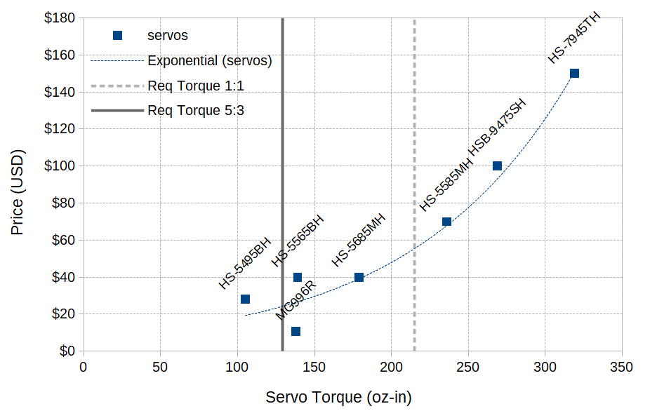
Almost all of the servos considered have sufficient torque with a gear ratio of 5:3. However, required torque isn't the only consideration. Early testing with the Hitec HS-5685MH found that while the servo had sufficient torque, the gears would strip. The brass gears were unable to handle the the shock and vibration environments and so a steel or titanium gear servo was required. The HSB-9475SH with steel gears was then selected since it's one of the cheapest servos with the required type of gear.
Electronics
The heart of the EVPR is the ESP32 micro-controller. Currently a Sparkfun ESP32 Dev Board is used. The electronics are placed as close to the center of the hub as possible to lower the centrifugal forces experienced.
For now, a minimum of two ESP32s are required for the EVPR. The first is connected to the flight controller via a UART connection and acts as a master node. It's purpose is to act as the access point and broadcast the servo commands from the flight controller. The controller on the rotor acts as a slave node, receiving the servo commands from the master node and commanding the servos via pulse with modulation (PWM) signals.

The firmware for the master and the slave nodes was written using the ESP-IDF framework. The source code can be obtained from the git repository at the follow links:
Currently the communication is one-way from the flight controller to the slave nodes. In the future two-way communications can be utilized so that the flight controller can receive status information from the individual rotors.
Power
The power required for the on-board electronics will be dependent of the blade torque requirements for a specific application. A simple power budget is shown below for the Goliath quadcopter as an example.
| Item | mA | Voltage | Count | Watts |
| Servos | 900 | 7.4 | 2 | 13.3 |
| ESP32 | 260 | 3.3 | 1 | 0.9 |
| Total | 14.2 |
Primary power for the on-board electronics is provided via batteries. Two 900 mAh LiPo cells are tied together to create a 7.4 V power source with 1800 mAh capacity. At peak power draw the batteries will last about 28 minutes.
In the future an axial flux generator will be added to the rotor hub to act as the primary power supply and the batteries will serve as a back-up. Four EVPRs added to #Goliath - A Gas Powered Quadcopter will a minimum of 60 W. The gas engine is capable of providing 22 kW (30 Hp), so the percentage of power used for the rotors would be 0.03%. Even if the power budget doubles, it's still less than 1% of the total power available.