 Frank Buss
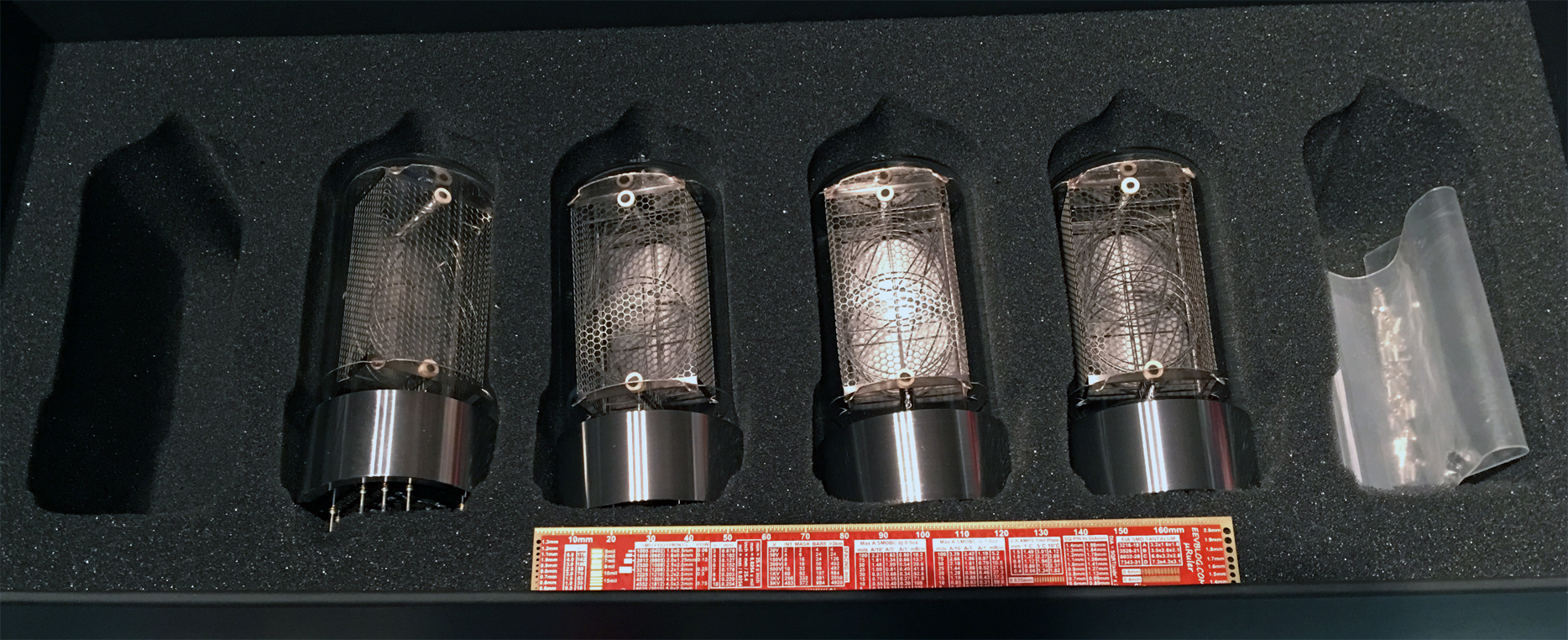
I have already too many project, so let's start another one. I bought a broken mechanical clock and then looked for some Nixie tubes. There are nice ones at eBay. One of the best looking Nixie tube is the Z568M. Usually they cost more than $200 on eBay, and they get sold for this price. Nothing wrong with it and the production quality is high, so it will probably last many years. But there is a new manufacturer, who creates a new version of this tube, see http://www.daliborfarny.com , each one hand-made, and with 10 years warranty.
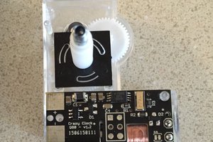
I bought some, and they are gorgeous. This is the packet packet when it arrived :
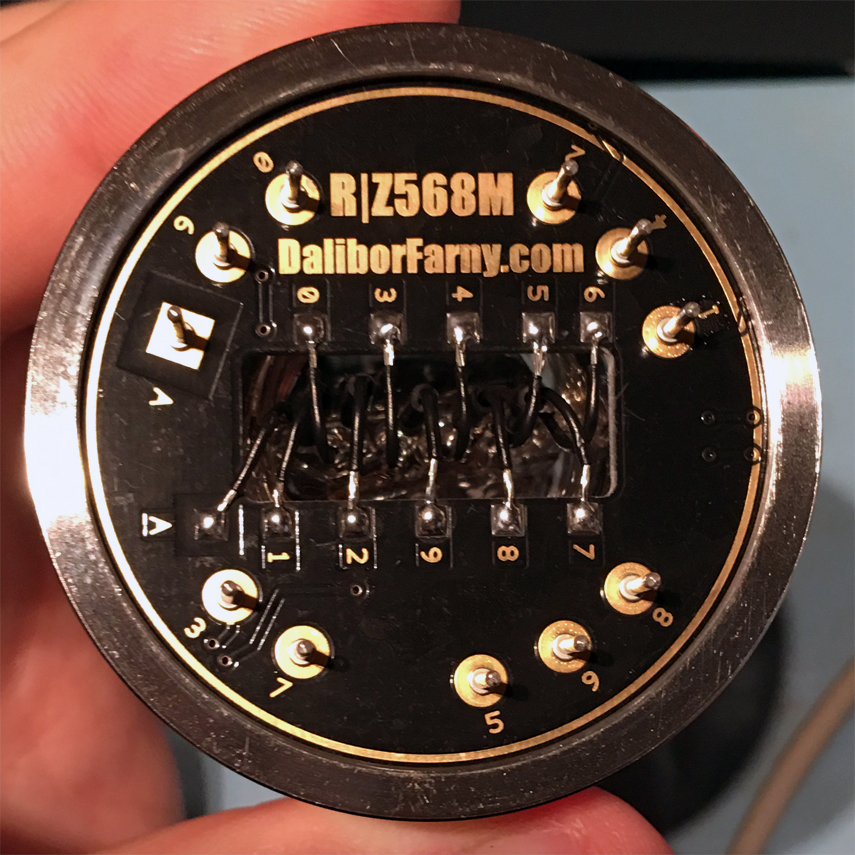
Bottom side:
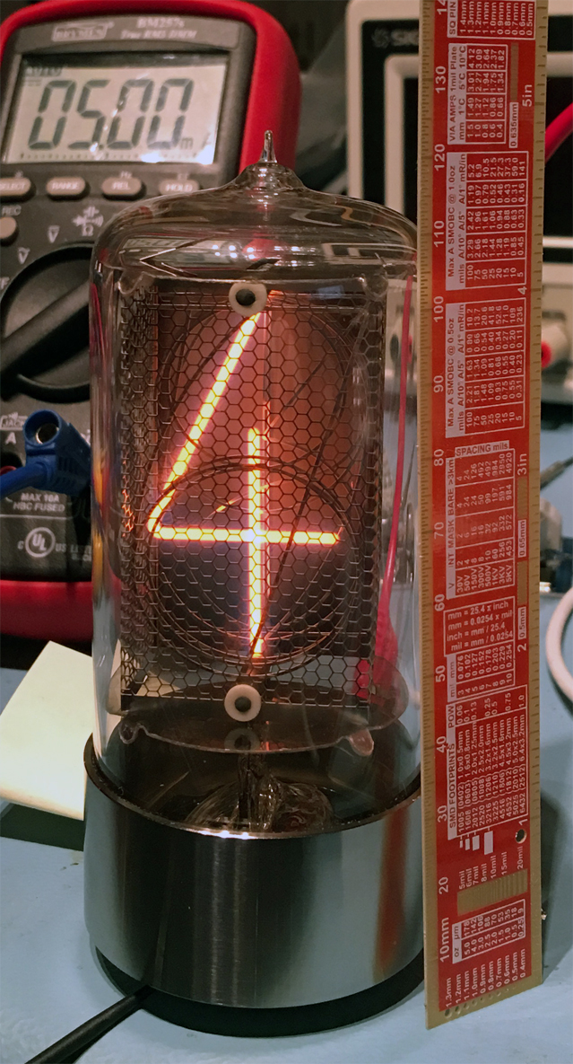
and a quick test, it looks so beautiful!
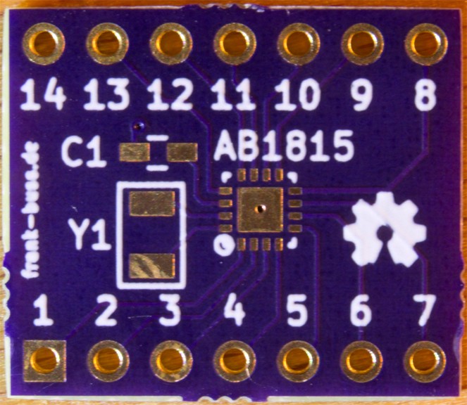
Now I'll design the circuit board for it.
Surprise: I just opened the clock and it comes with a built-in audio device :) This brings back memories, I remember the sound, my grandparents had such a clock (I think each full hour or at 12 o'clock: dong - dong - dong...). Will add some solenoids.
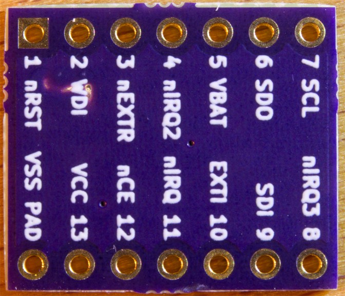
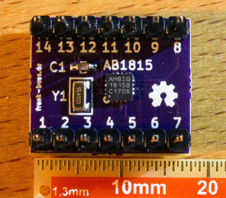
Github project: https://github.com/FrankBuss/nixie-clock


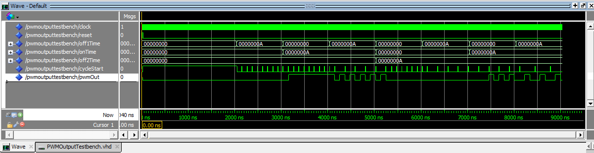
 This is the PWM signal which the Arduino sketch creates, tested with LEDs:
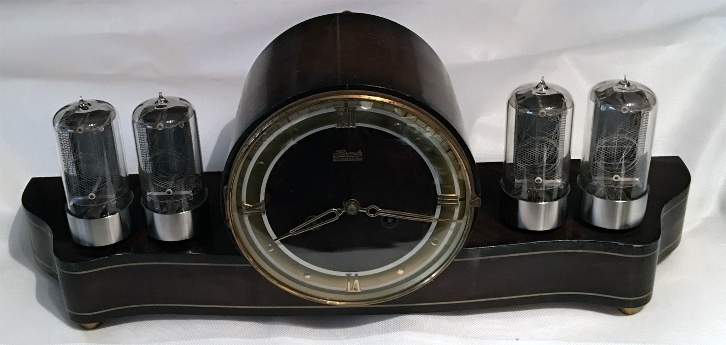


 Benchoff
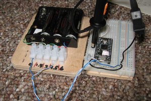
 Nick Sayer
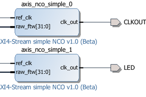
 Antti Lukats
That was a time when all I wished as a splendid-looking clock like that. Hey wait, this time is now!!! (puns intended)