 Changyi Gu
INTRODUCTION
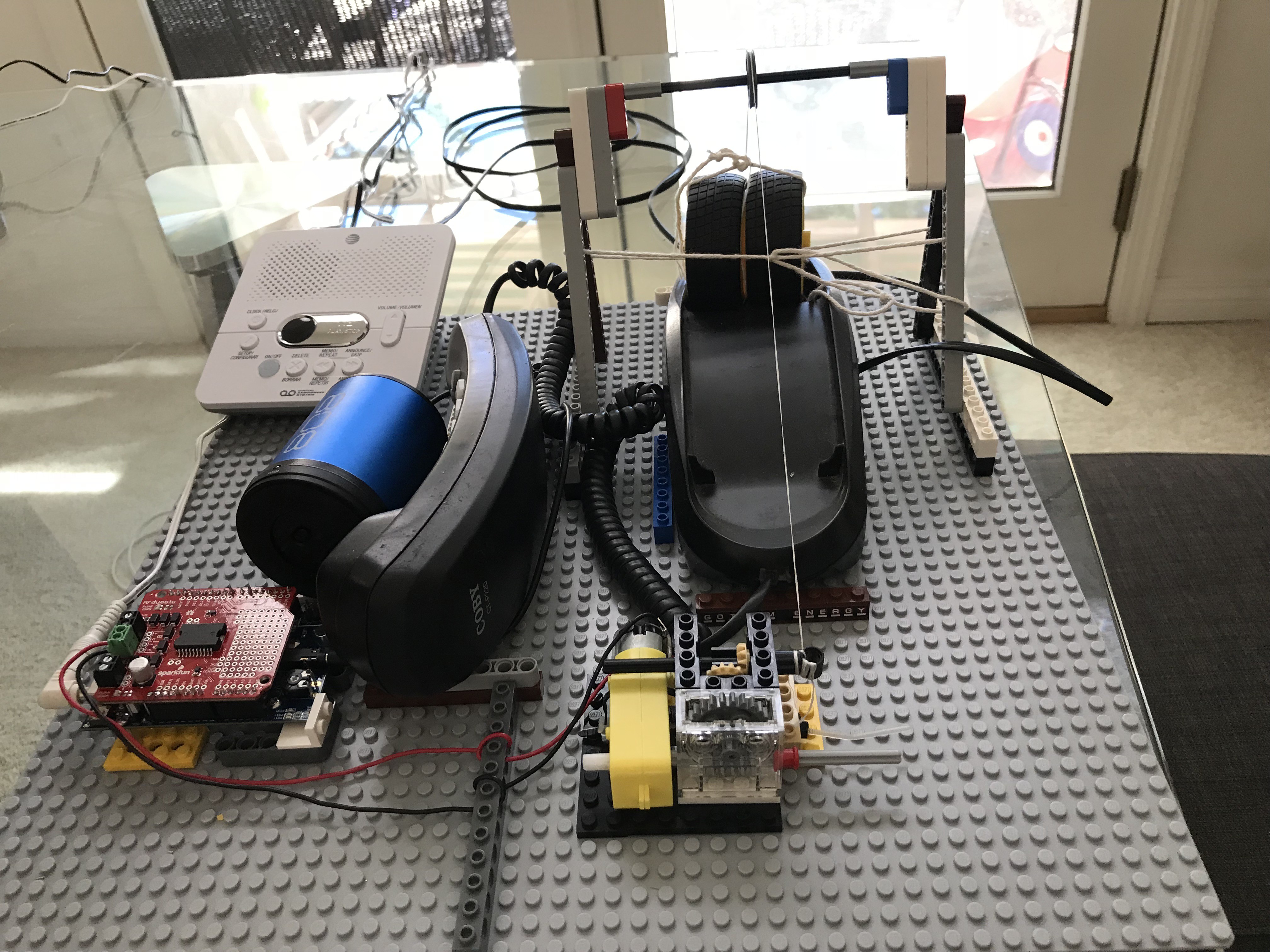
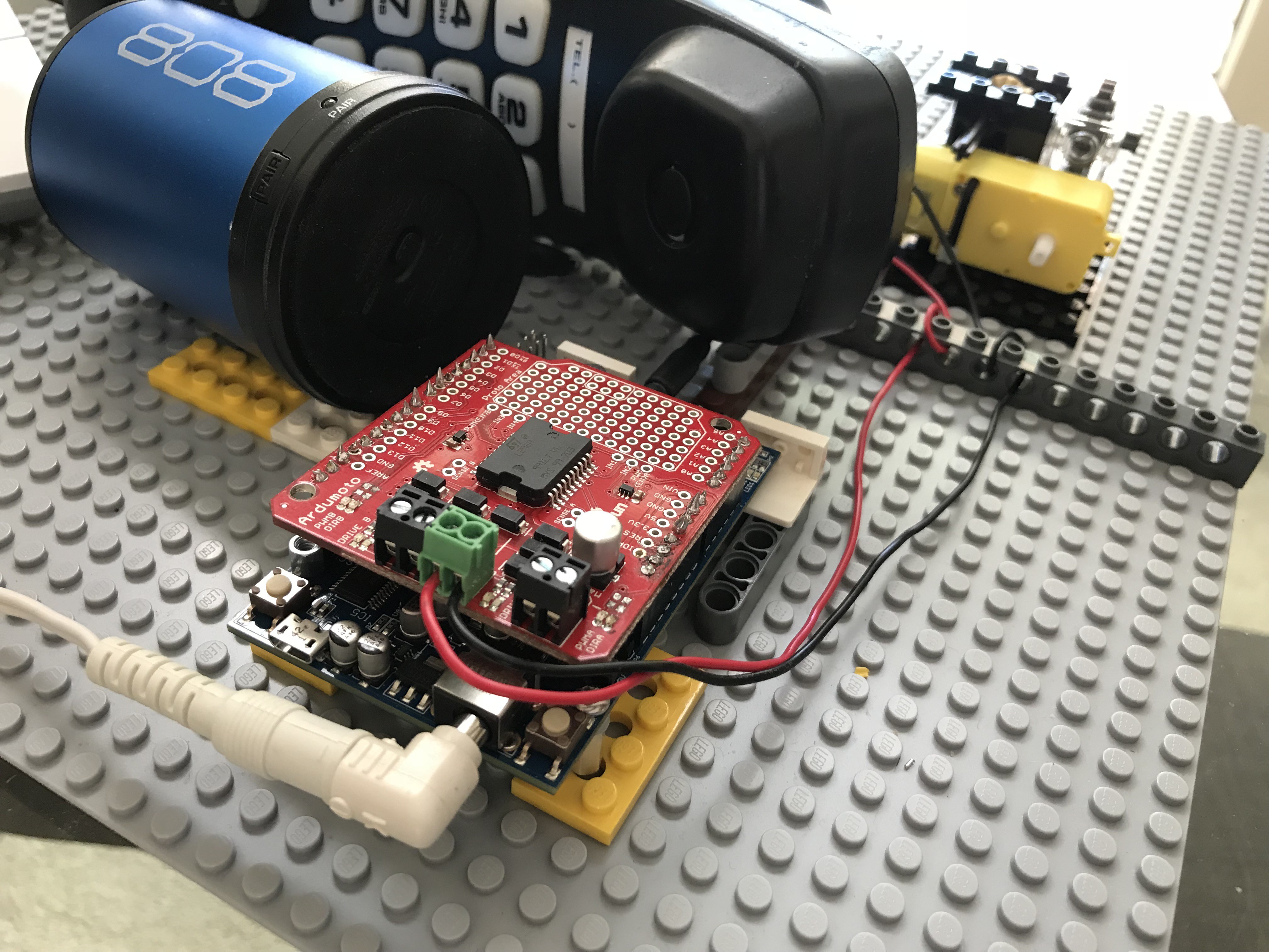
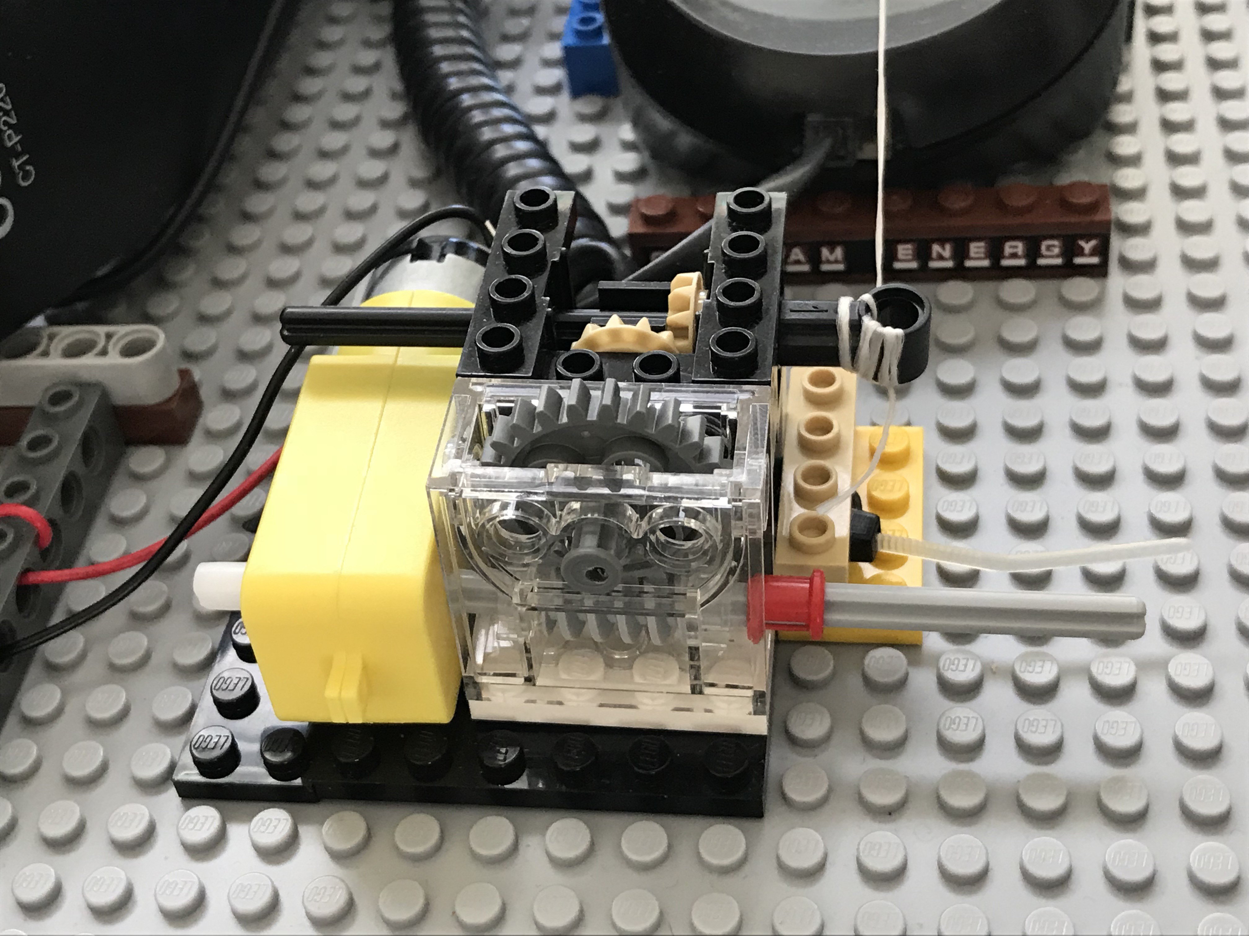
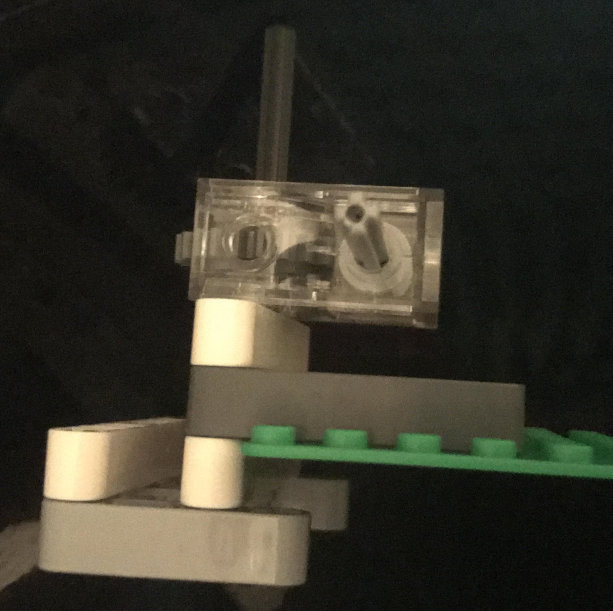
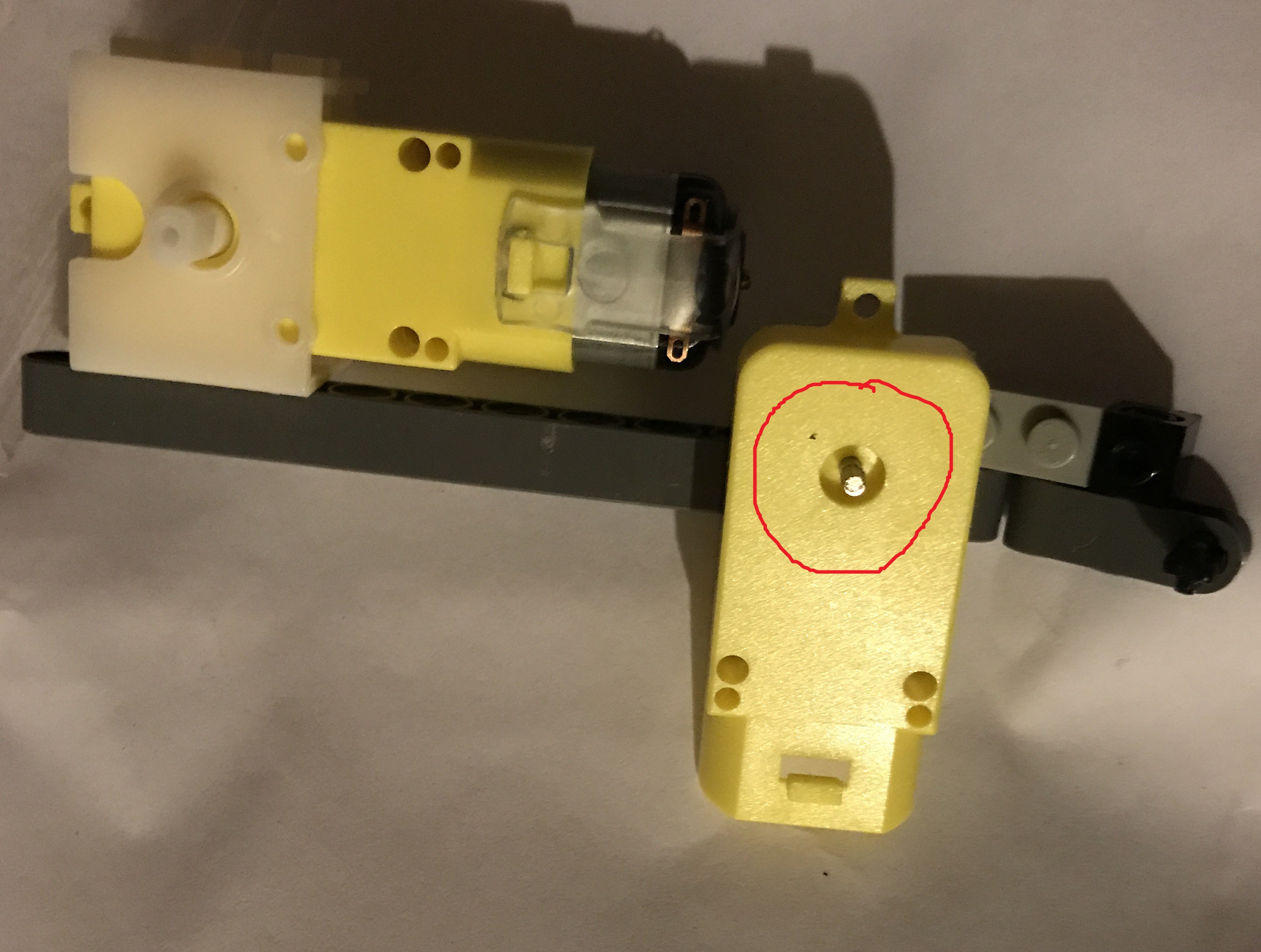
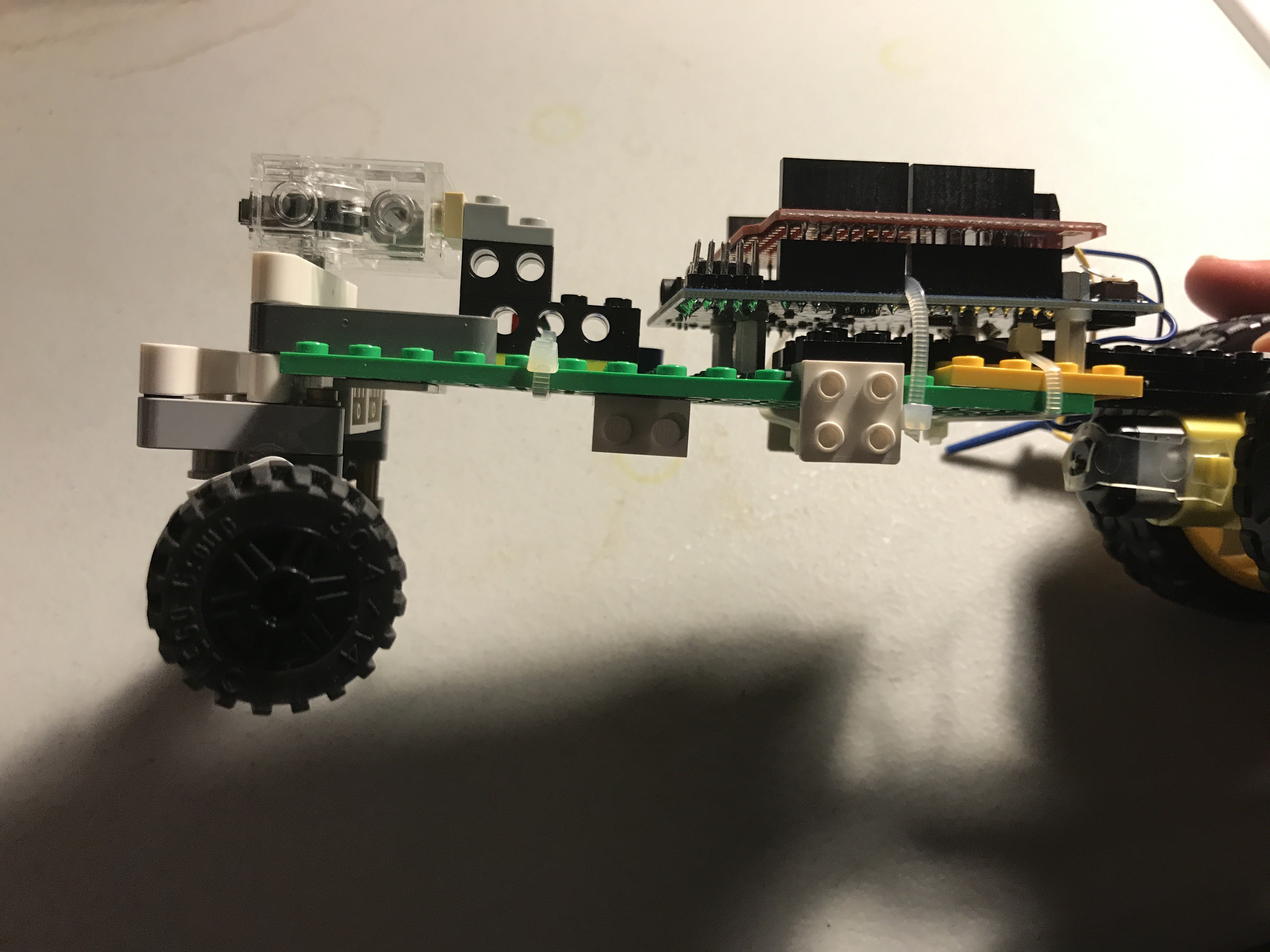
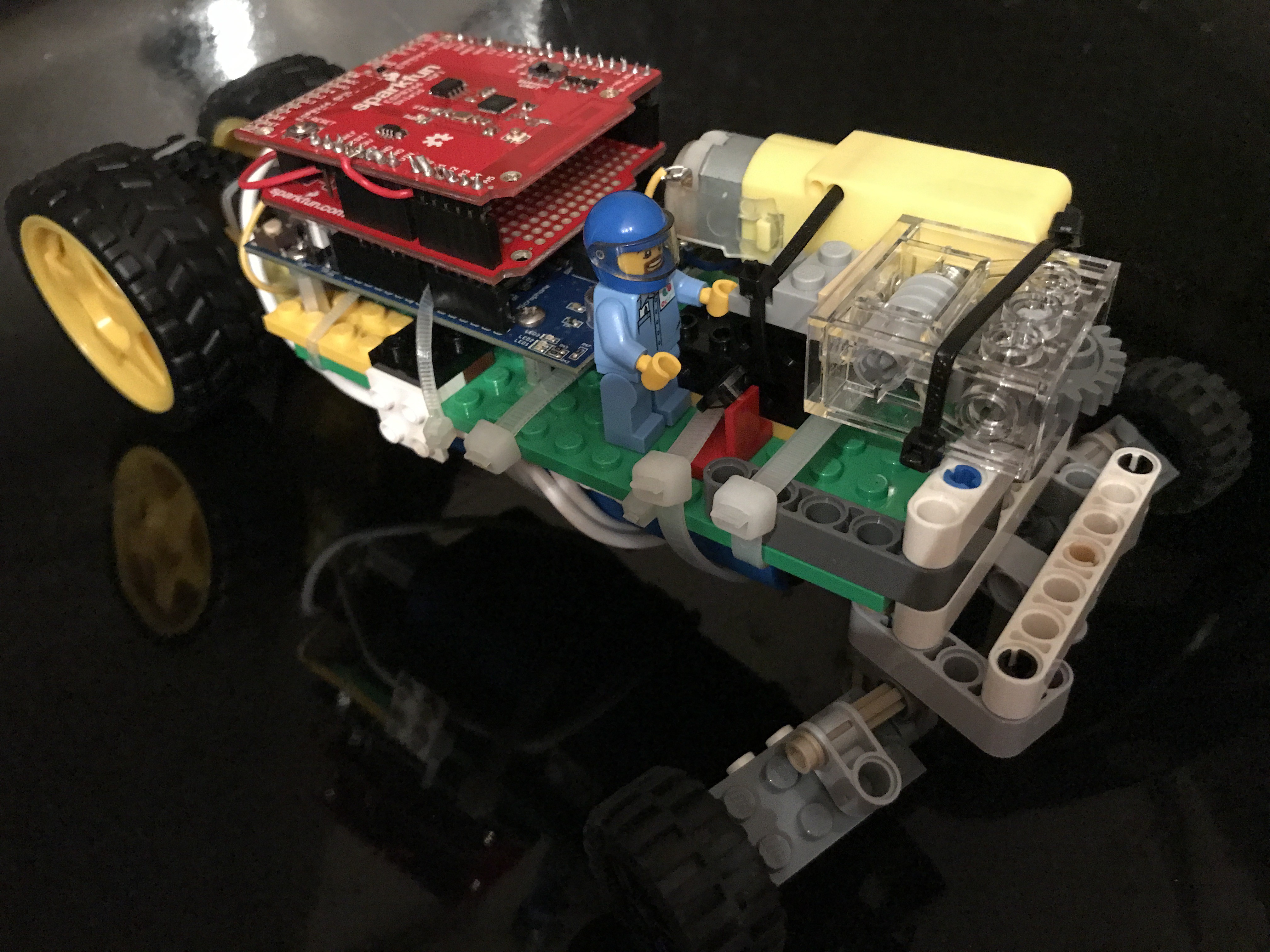
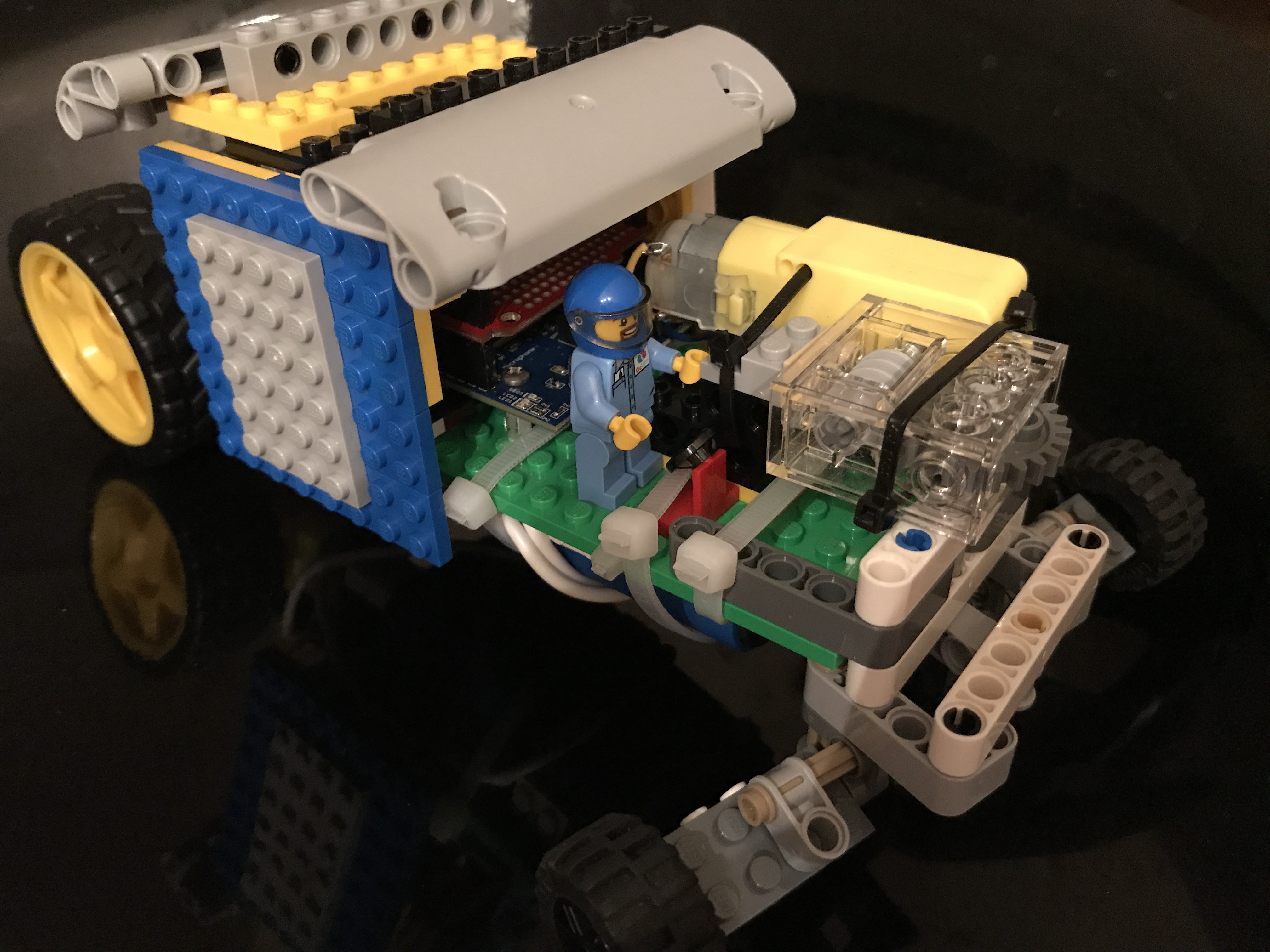
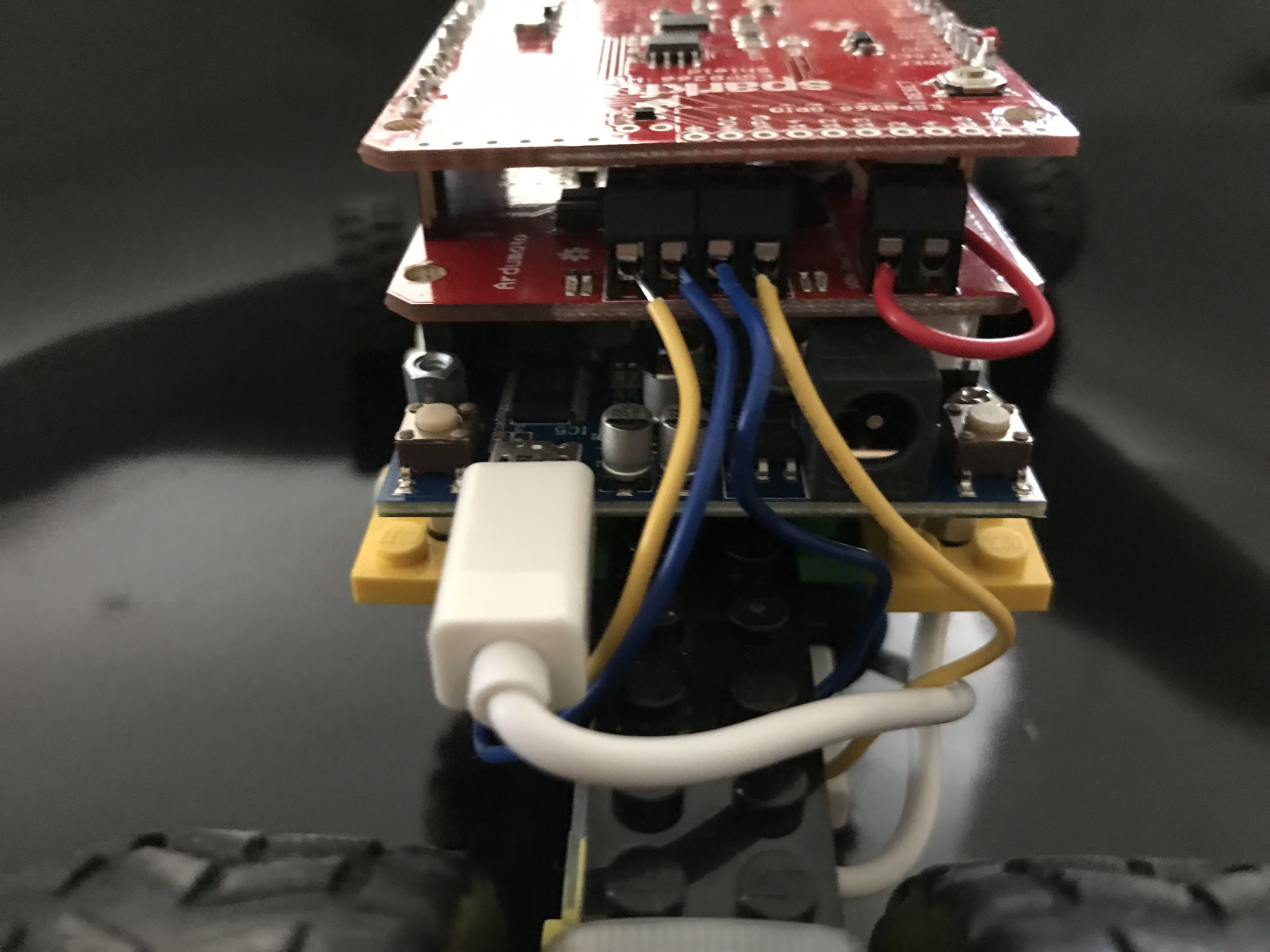
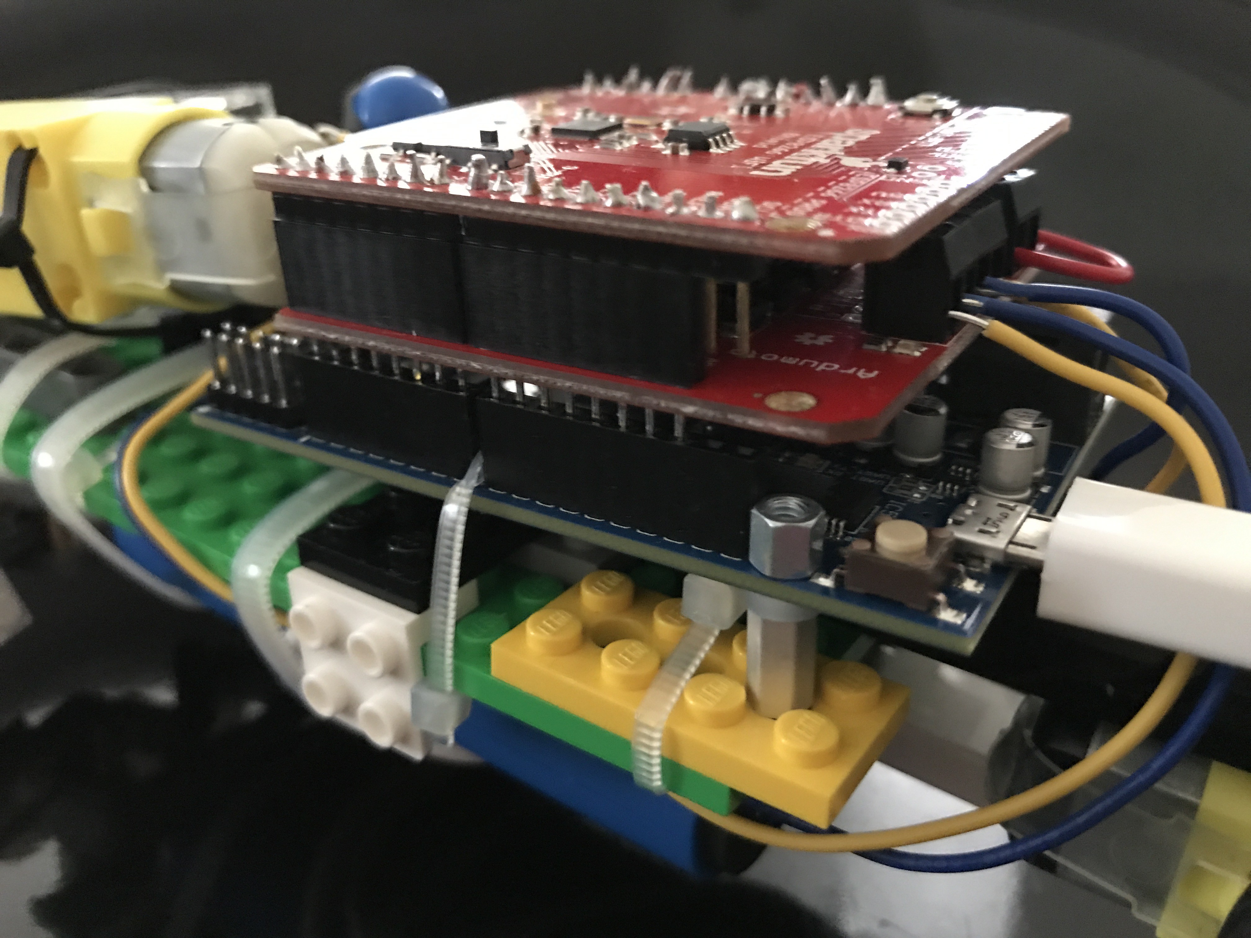
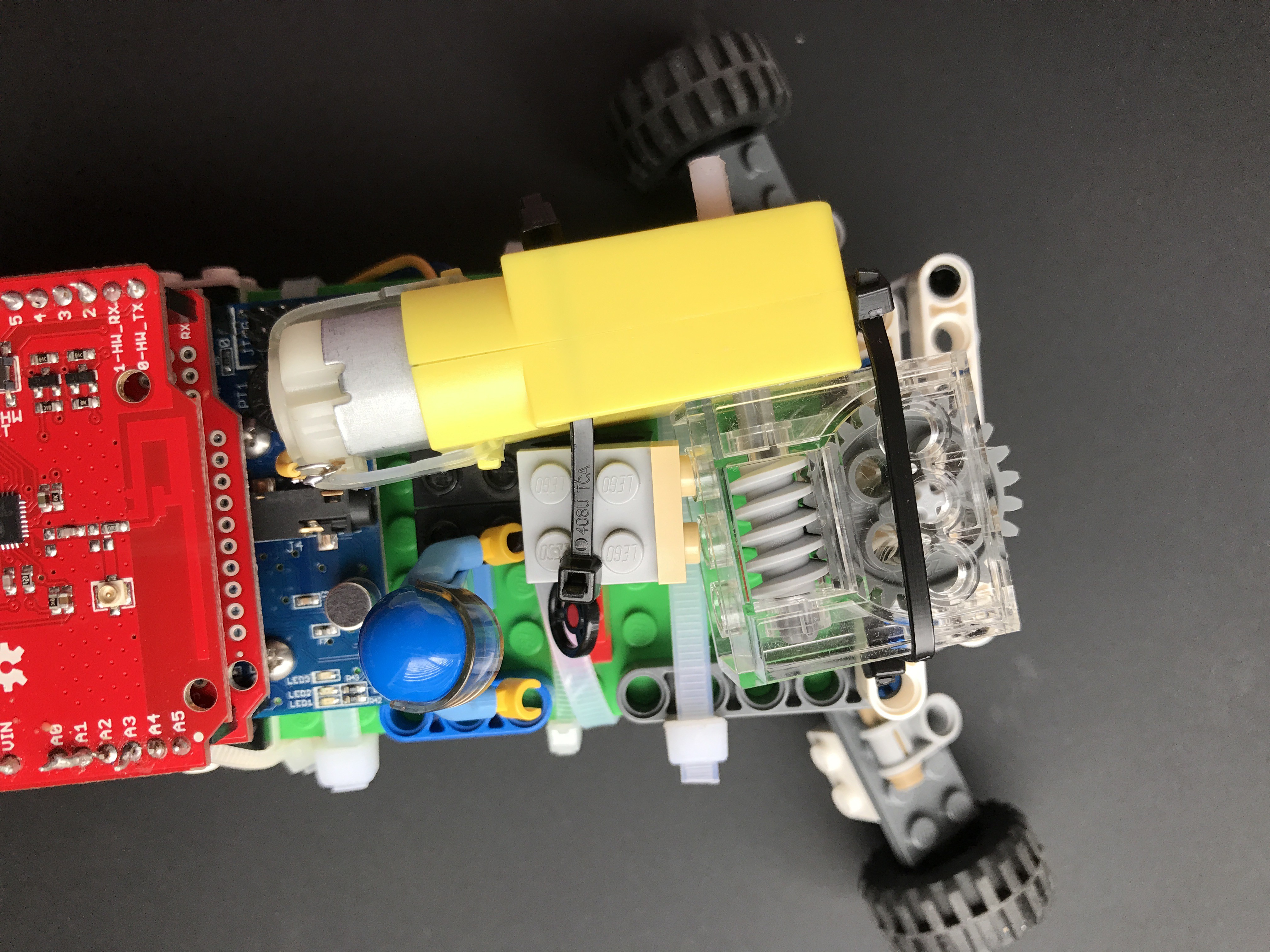
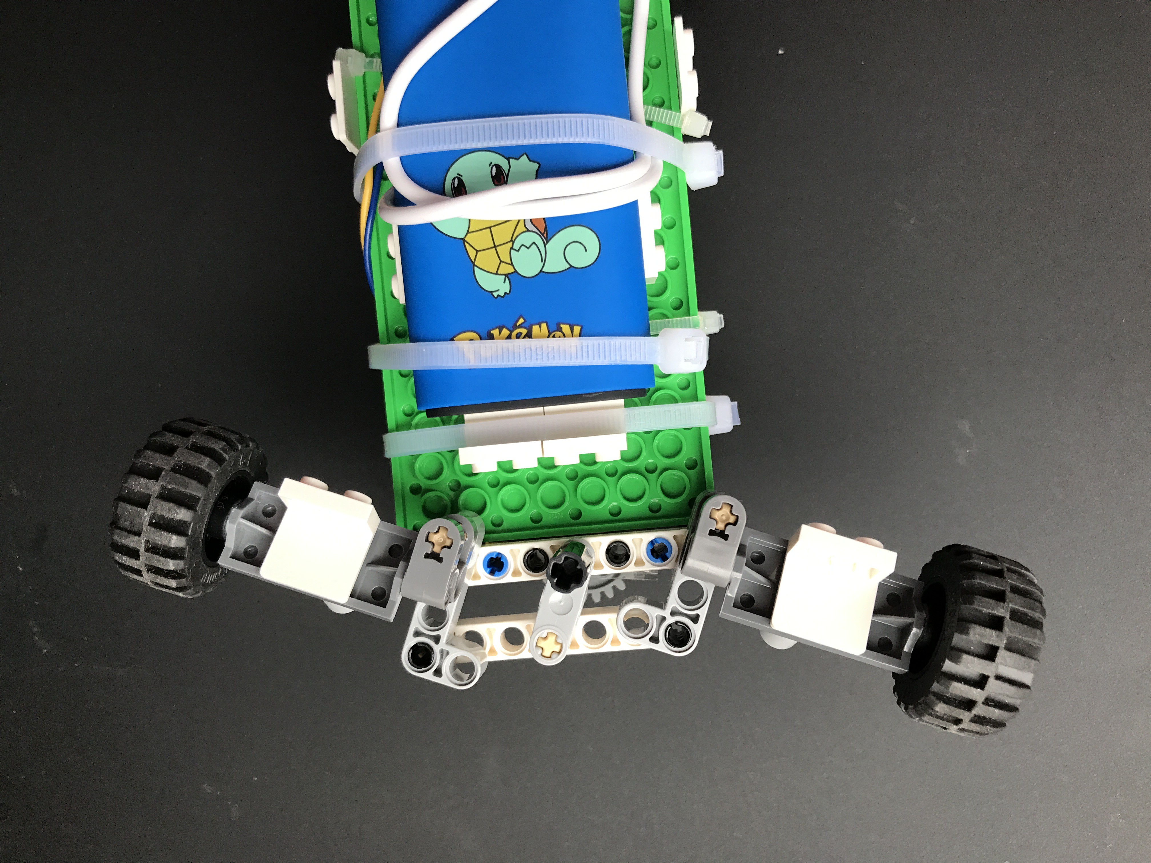
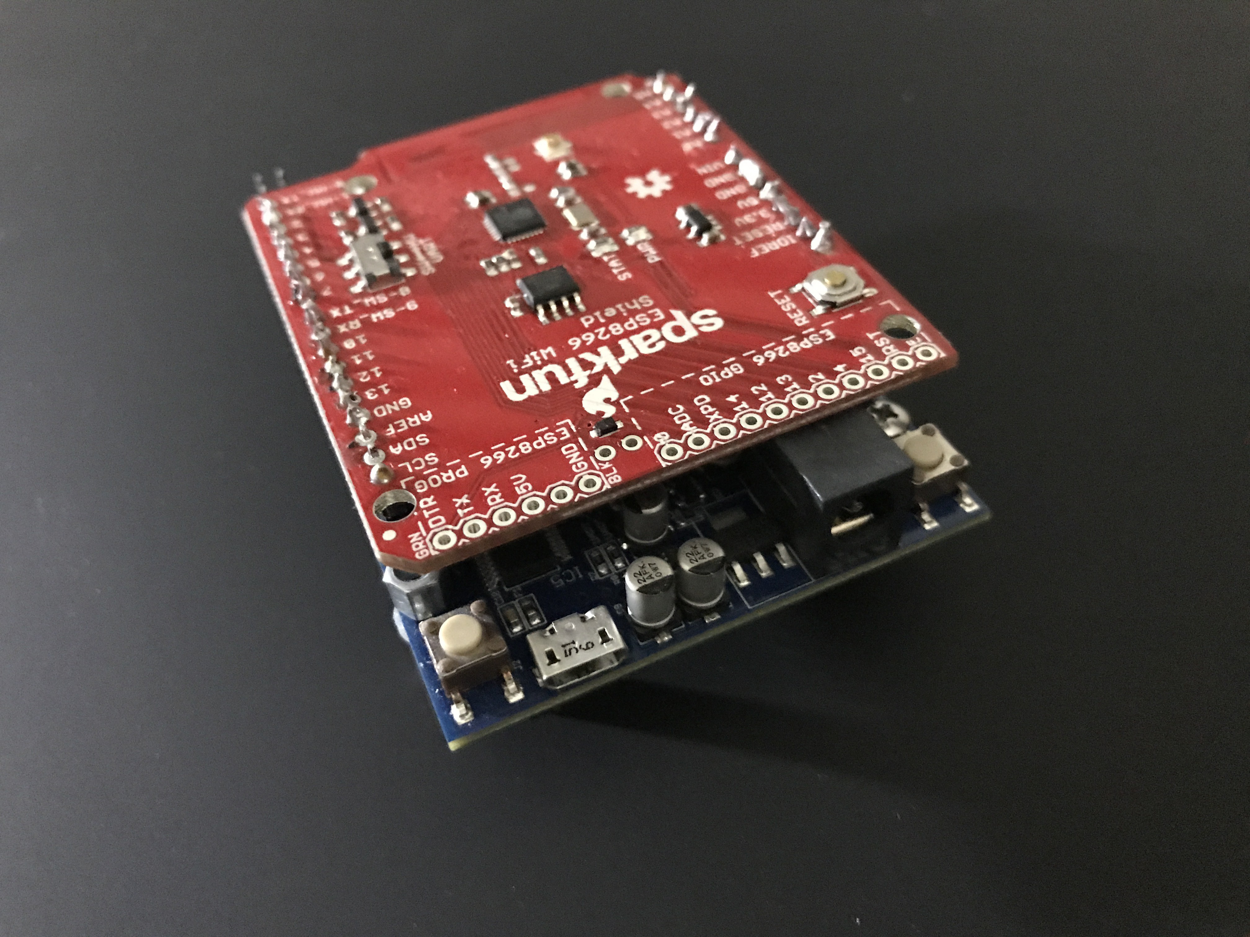
Before you start, read this post to see how to make a Stick Shift Monster Truck with, and this post to see how to make a home automation system. Both projects feature PulseRain M10 as the core module board.

==================================================================
==================================================================
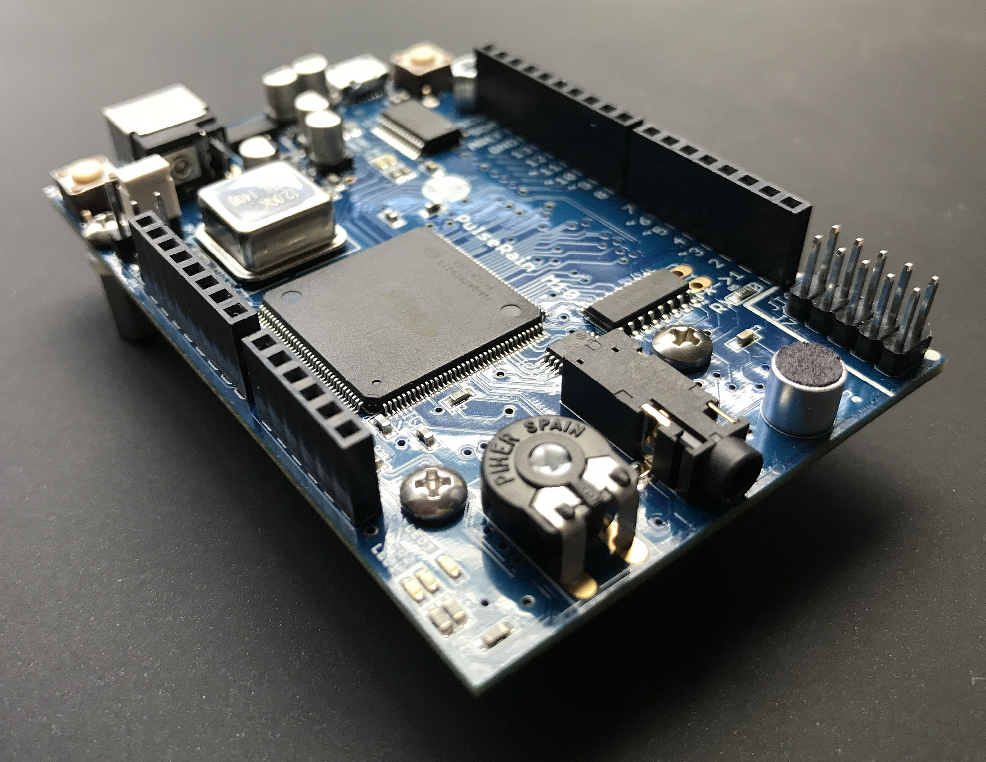
The PulseRain M10 Board is a versatile and expandable platform that can fit in a wide variety of scenarios, as illustrated below:
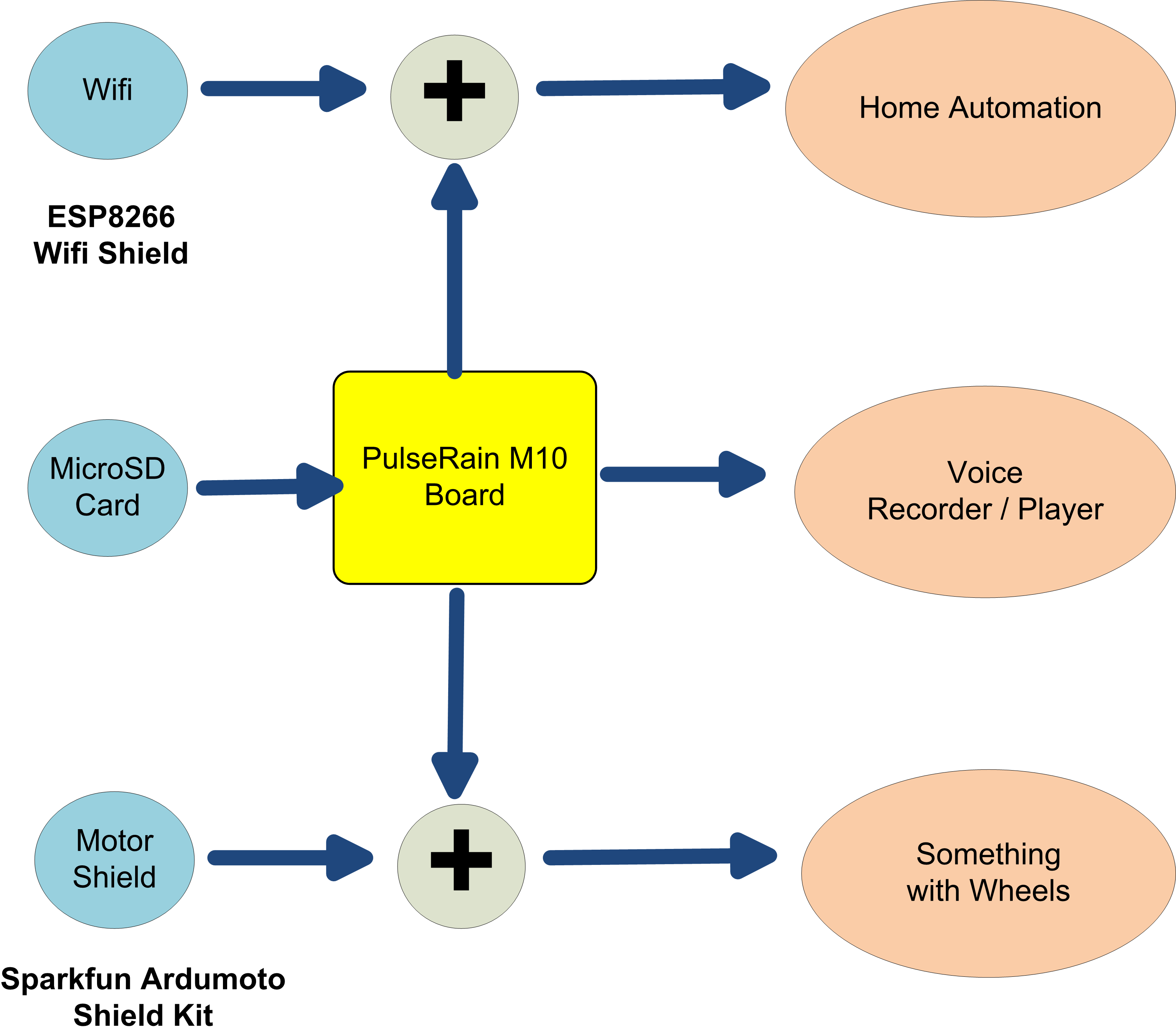
It is a FPGA platform that puts soft-core MCU into the FPGA, while presents a software interface and form factors like Arduino. It is an open source answer to the dominant proprietary solutions in the embedded systems, and it also offers the flexibility that standalone MCUs can not match. The great features it bears are as following:
- Open Source Hardware
The schematic and layout are designed with Eagle CAD. The PCB design files can be found on GitHub, and they are licensed under "Creative Commons Attribution Share-Like 3.0".
The processor core and peripheral libraries (in System Verilog) are licensed under GPLv3. And for those who want to use them in ways that are incompatible with the GPLv3, we also offer commercial license instead.
All the firmware(sample code, libraries in C/C++) are licensed under LGPLv3 (GNU Lesser General Public License).
All the desktop software (Python script and utilities) are licensed under Apache License Version 2.0.
And the fine print of the license agreement can be found here, which is the official document that carries legal weight.
- Versatile
This platform has the bells and whistles for common embedded applications, such as:
- 8 channel onchip ADC in FPGA with temperature sensing diode
- Onboard MicroSD socket. SD card controller as a peripheral in FPGA. MCU driver supports FAT32 file system.
- 128KB onboard RAM (Microchip 23LC1024). 40KB onchip RAM for code/data in FPGA.
- Silicon Lab Si3000 Voice Codec.
- Switchcraft 3.5mm Phone Jack for Speaker. Onboard Microphone from CUI
- FTDI FT232R for USB/UART
- 3.3V / 5V IO support with Texas Instrument TXS0108E Voltage Translator.
- PIHER 10mm Carbon Potentiometer
- 2 Push Buttons, 3 LEDS (Blue, Red and Green)
- DIODES, Inc. AP3429/A 1.0MHz, 2A DC-DC Buck Converter
- 14 bit of Digital IO on Arduino Connector, 10 Position JTAG Connector that can be used for GPIO as well.
- I2C / SPI / PWM Peripherals in FPGA
- Expandable
M10 board's form factors are compatible with Arduino Shields in connector and mounting hole positions. The onboard FPGA (Altera 10M08SAE144C8G) can be migrated to a device as big as 25K LE, 675Kb BRAM, or as small as 4K LE, 189 Kb BRAM.
And all the peripherals are connected to the processor core through the open source Wishbone FASM bus interface, which gives users the greatest choice possible to add new peripherals. In this way, the hardware can be tailored to users' specific application.
- Software Friendly
Arduino IDE can be used as GUI based development environment. Starting V1.5, Arduino IDE has support for 3rd party hardware integration. All you have to do is to point the "Additional Boards URL" to our GitHub repository in "File/Preference/Additional Boards URL". And then install the board support package in "Tools/Boards/Boards Manager".
- DFM (Design for Manufacturing)
- Regular shape (2.1 inch x 3.2 inch rectangular shape)
- Pass DRC: Minimum Trace Width: 8 mil, Minimum Trace Clearance: 8 mil, Trace to Board Edge Clearance: 8 mil, Minimum Via Drill Diameter: 10 mil, 62 mil board thickness.
- No Leadless Package (The FPGA is in TQFP 144 package).
- ENIG (Electroless Nickel Immersion Gold) Finish for PCB fabrication.
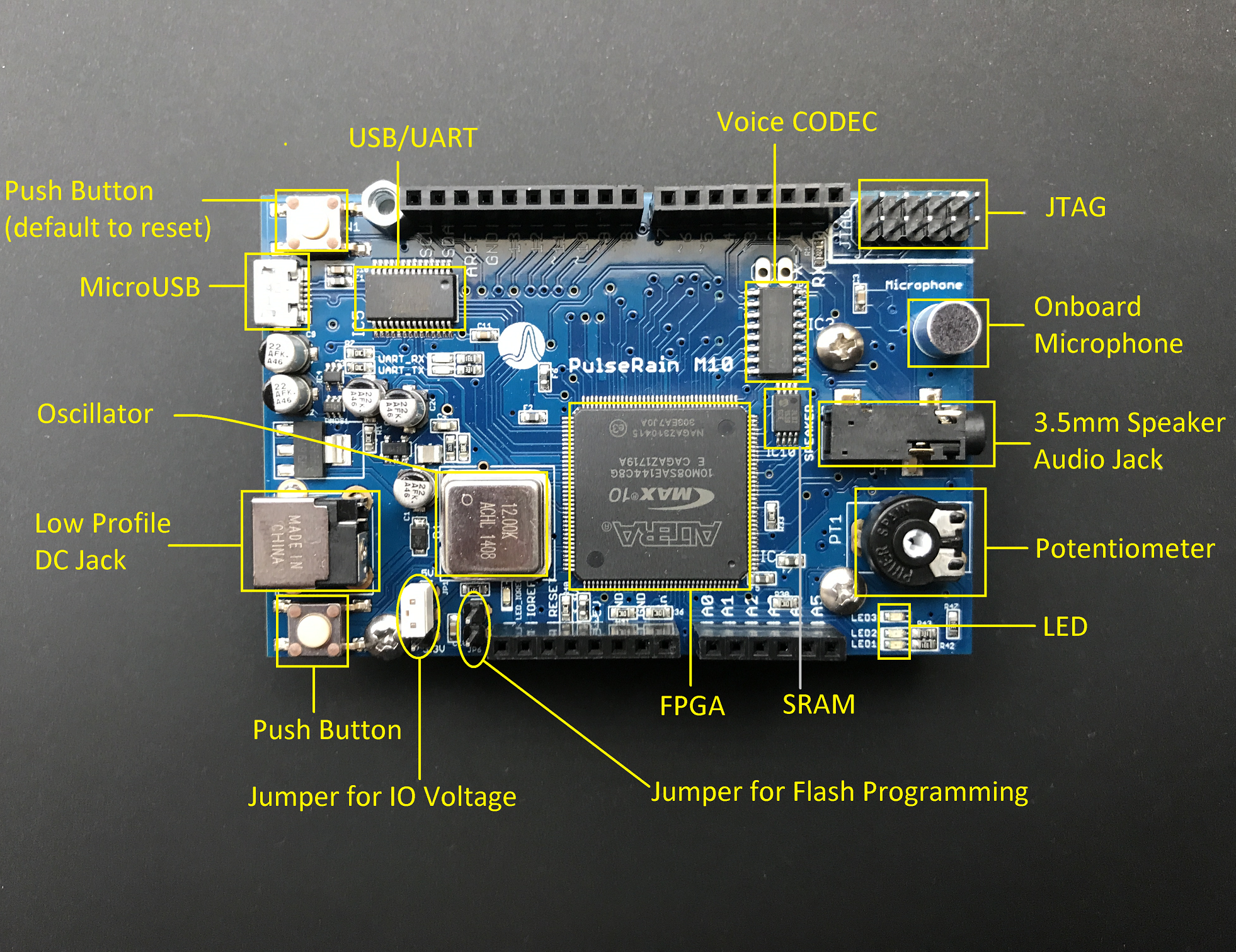
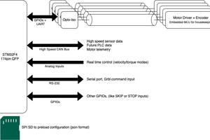
HARDWARE ARCHITECTURE
The architecture of M10 board is illustrated in the figure below. The FPGA we choose is Altera 10M08SAE144C8G that features 8K LE, 378Kb Block RAM, 172 KB flash memory, a 8-channel A/D converter with temperature sensing diode. Out of the box, we have pre-loaded...
Read more »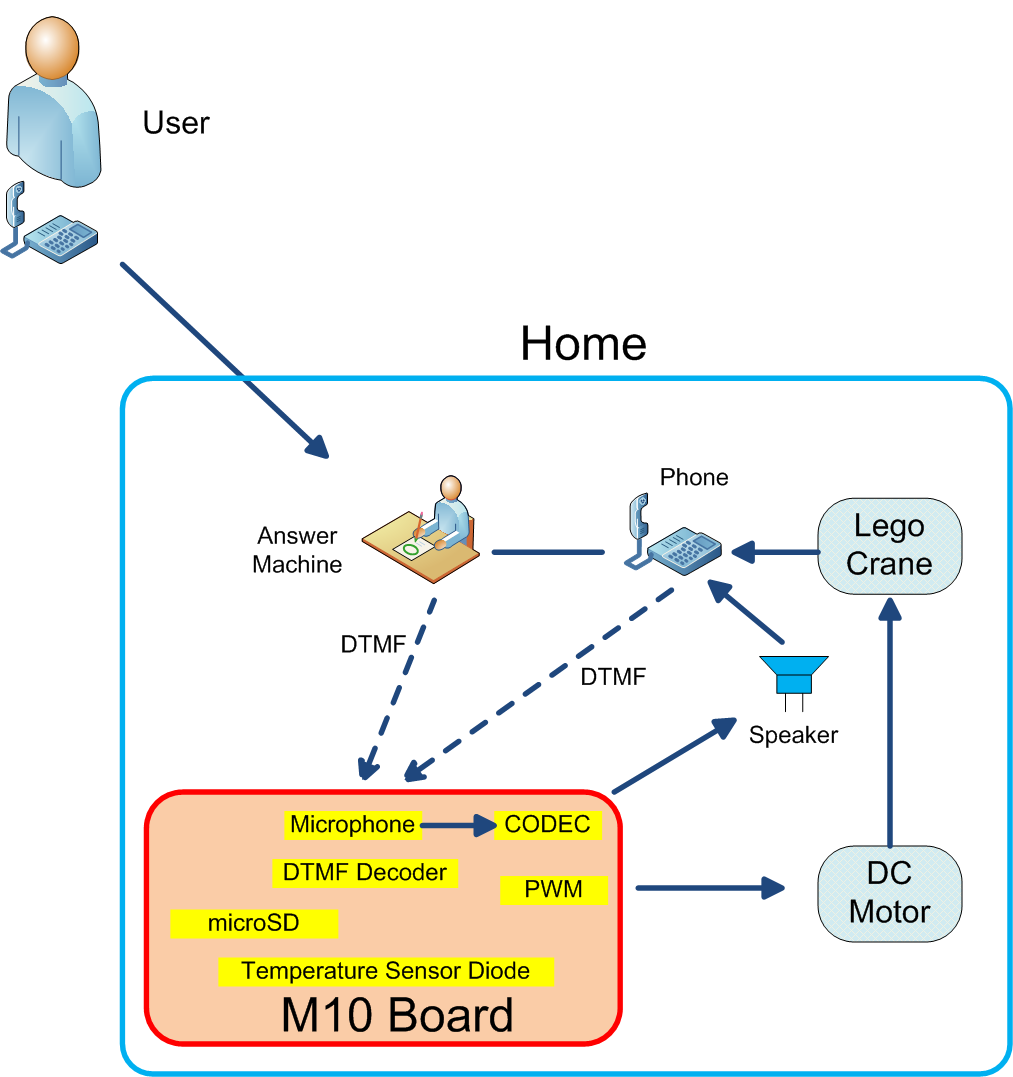


 plugg.ee Labs
 Oskar Weigl
 Tsjakka
I want one of these - what's the approximate retail cost based on 1,000 units?