 Capt. Flatus O'Flaherty ☠
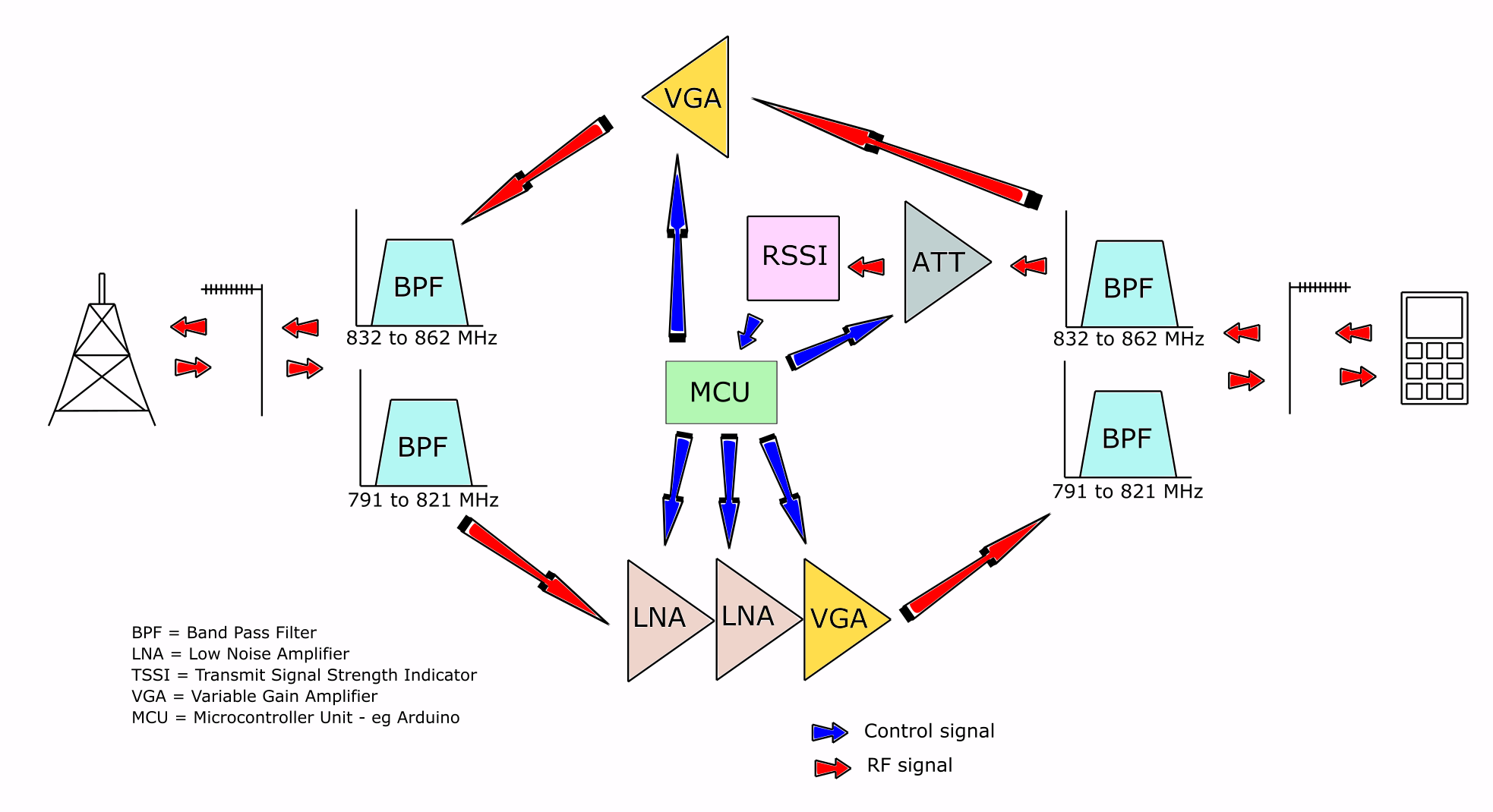
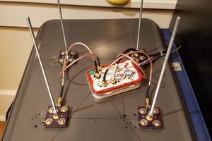
The 4G signal from the local base station is captured using an external logarithmic Yagi antenna mounted high up on a pole. The external antenna is pointed directly towards the base station and needs to have 'line of sight' which means that there are no major obstacles such as large buildings, hills and trees in the way. 'Line of sight' does not mean that we have to actually see the base station, it's more of a theoretical term and really just means 'no major obstacles'. 4G signals generally have good penetrating ability but do not like going around big objects.
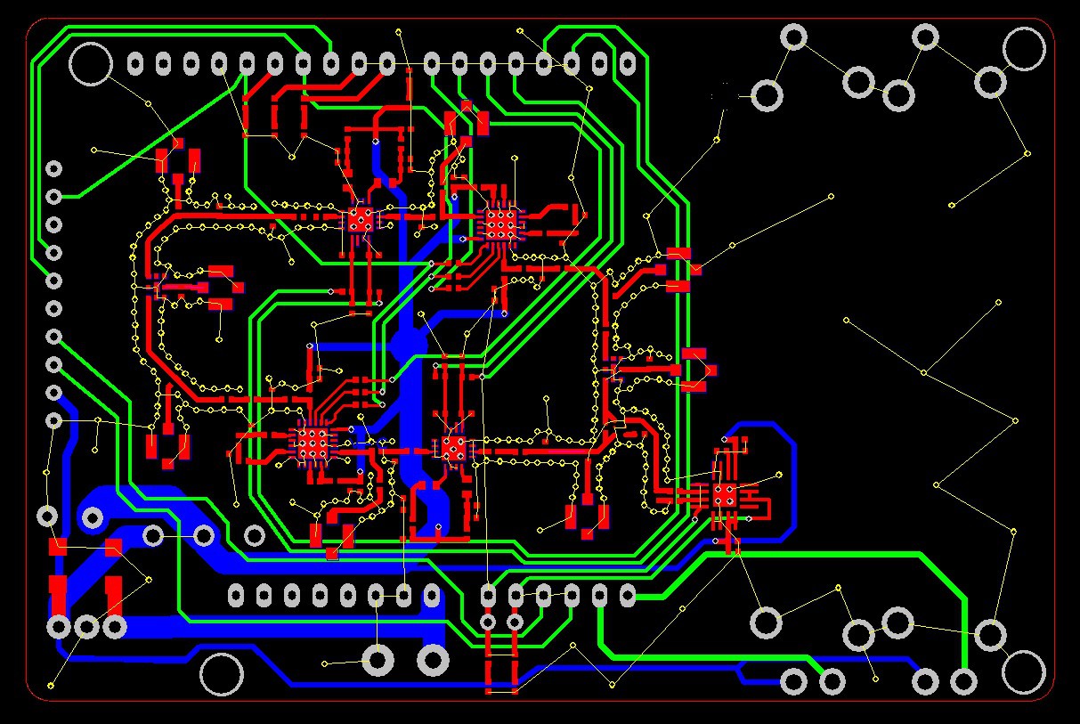
The signal then travels through a low loss coaxial cable and is routed into the Rx (791 to 821 MHz for my network) port on the duplex band pass filter (BPF) on the left hand side of the diagram above.
Following the red arrows in the diagram, the signal is routed into a low noise amplifier (LNA) which can be configured using the Arduino in three possible ways: 'Off', 'One LNA' and 'Both LNAs'. Selecting both LNAs can provide 37.5 dB of gain with a noise figure of just 0.55 dB.
Next in the signal path is the variable gain amplifier (VGA) which is controlled by the Arduino using the SPI bus. This component actually contains two amps cascaded together giving a total possibility of four cascaded amps in the whole Rx part of the circuit. The VGA is capable of adding another 32 dB of gain to the signal and can handle up to 1/2 watt of power with a noise figure of 1.5 dB.
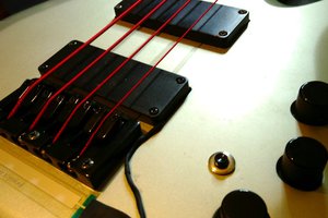
Since the circuit can pick up some unwanted interference, the signal is now routed into a second identical BPF which then connects to a plate antenna located inside the building. The BPF filters are 'duplexed' which allows the same antenna to be used for Rx and Tx simultaneously.
The strong signal transmitted from the cell phone is typically about 1/4 watt when far away from the base station and weaker when close to the station. The circuit has a VGA for transmitting the cell phone's signal back to the base station but this is not currently used as transmitting noisy or very strong signals to the base station can damage the network. Instead, the duplexer is used to monitor the strength of the cell phone's signal via a 'Received Signal Strength Indicator' (RSSI) chip which can be used to check that network compatible phones are present. Compatibility is determined by the actual BPFs selected as they have different frequency bands for each network.
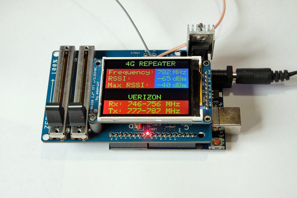 In an attempt to win one of the top 5 Hackaday prizes I've managed to tune a repeater to the Verizon network on band 13 which should, hopefully, work in the USA. I did test the device using the LimeSDR as a signal generator to check that the band filters etc were working properly and ...... all seemed fine.
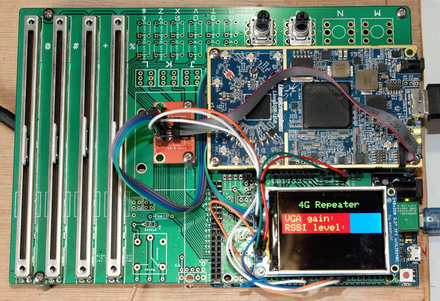
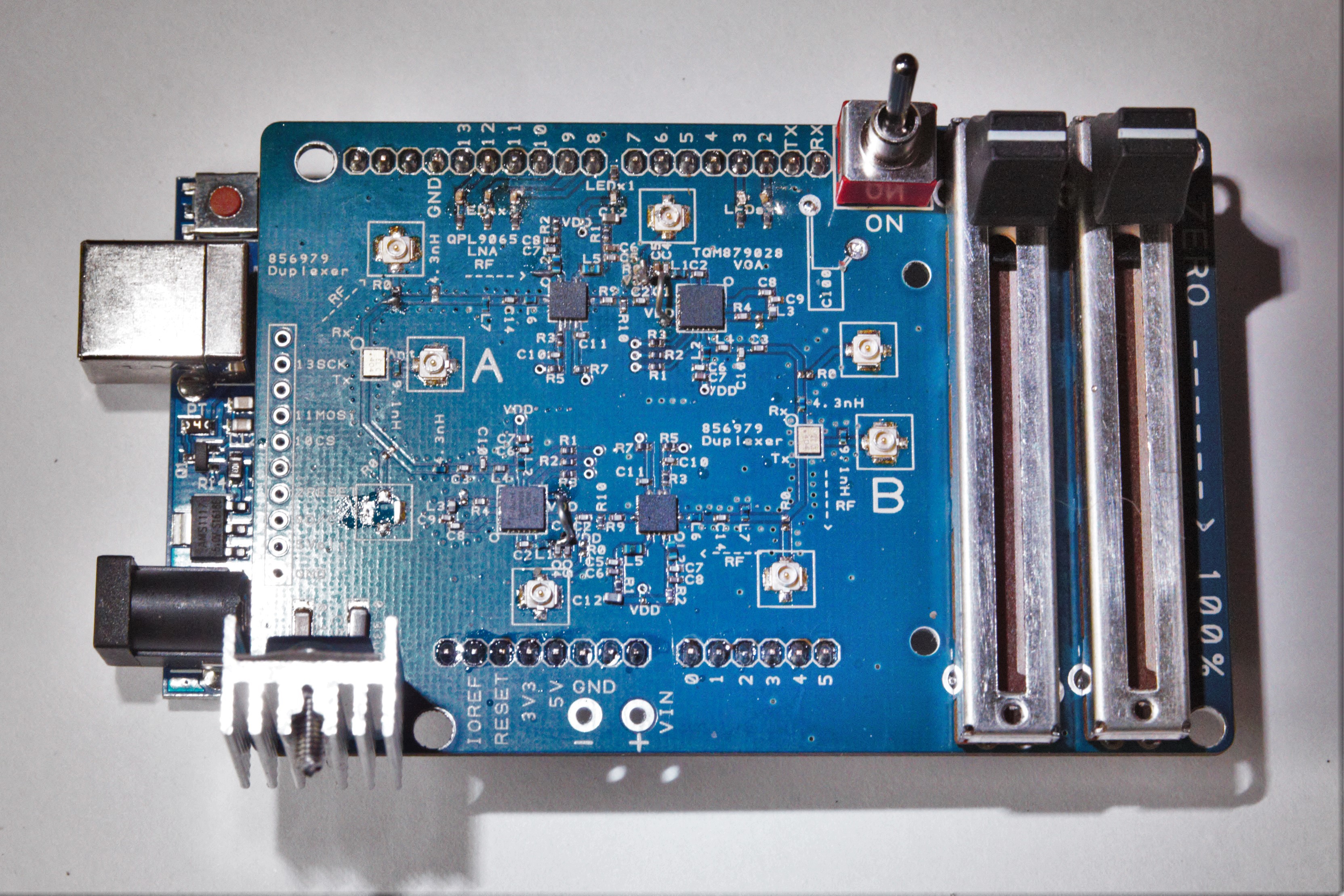 It's been a slightly frustrating couple of days, but I did discover 2 fairly serious errors, one of which I corrected with 2 pieces of bare wire. The other mistake was to try and control the LNA's using 5v instead of the recommended 3v - obviously I missed that somehow! Maybe this is why the LNA did not work, rather than bad soldering? Strangely, it did work on the previous incarnation with 5v.
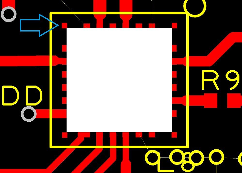
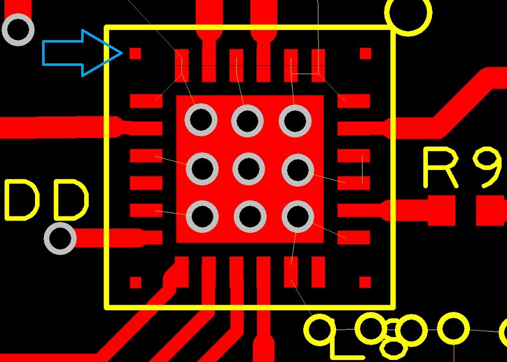
 Another 4 layers of abject confusion goes to Shenzhen, hopefully actually correcting a couple of mistakes found in the previous simplex version. Upon re-reading the datasheets for the amps I noticed that through holes are specified for thermal dissipation which should also make it easier to solder the chips, which seemed to me to be floating on a big bubble of solder on the central pad, not allowing the edge pads to make reliable contact. Hopefully that drama is over!
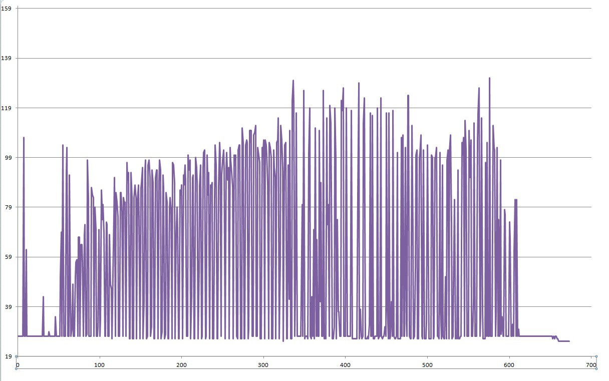 After a few initial spikes, the graph shows a gradual increase in signal strength as the VGA is turned up, reaching something of a plateaux where, presumably, the base station starts telling the phone itself to reduce it's power output.
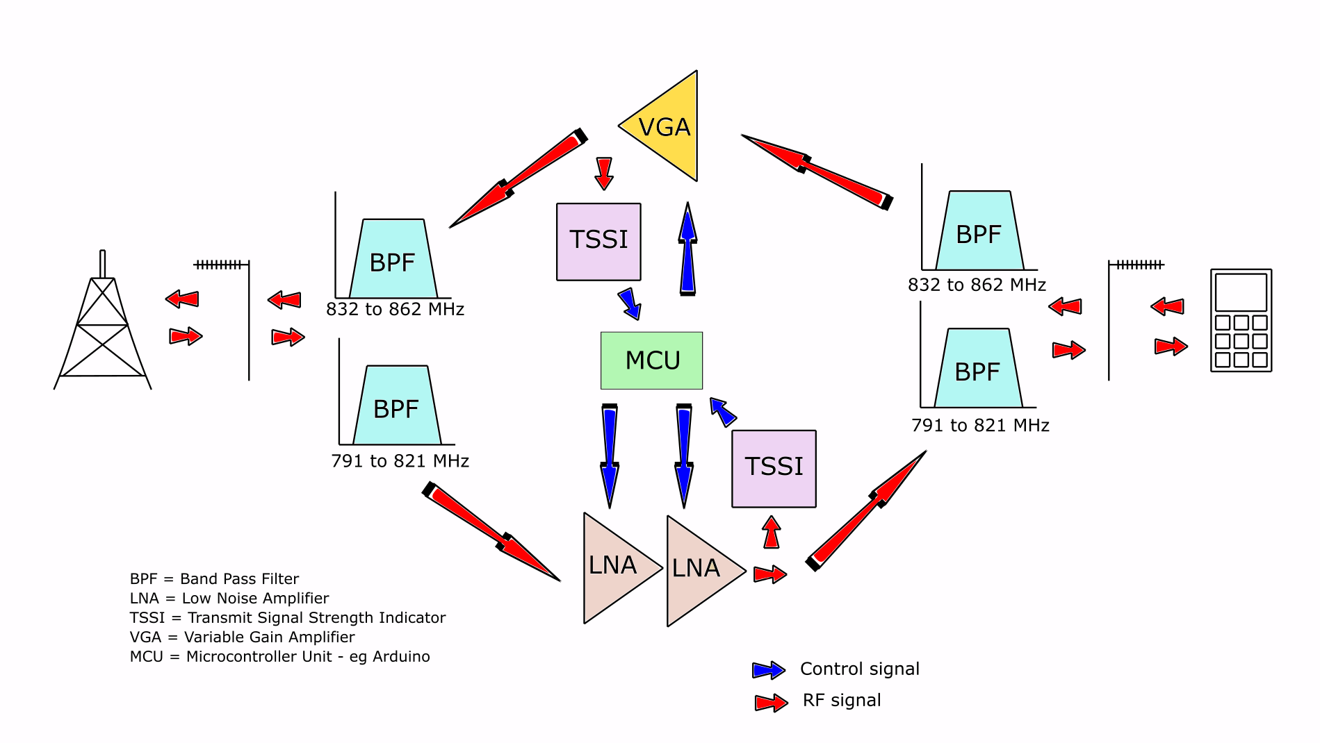
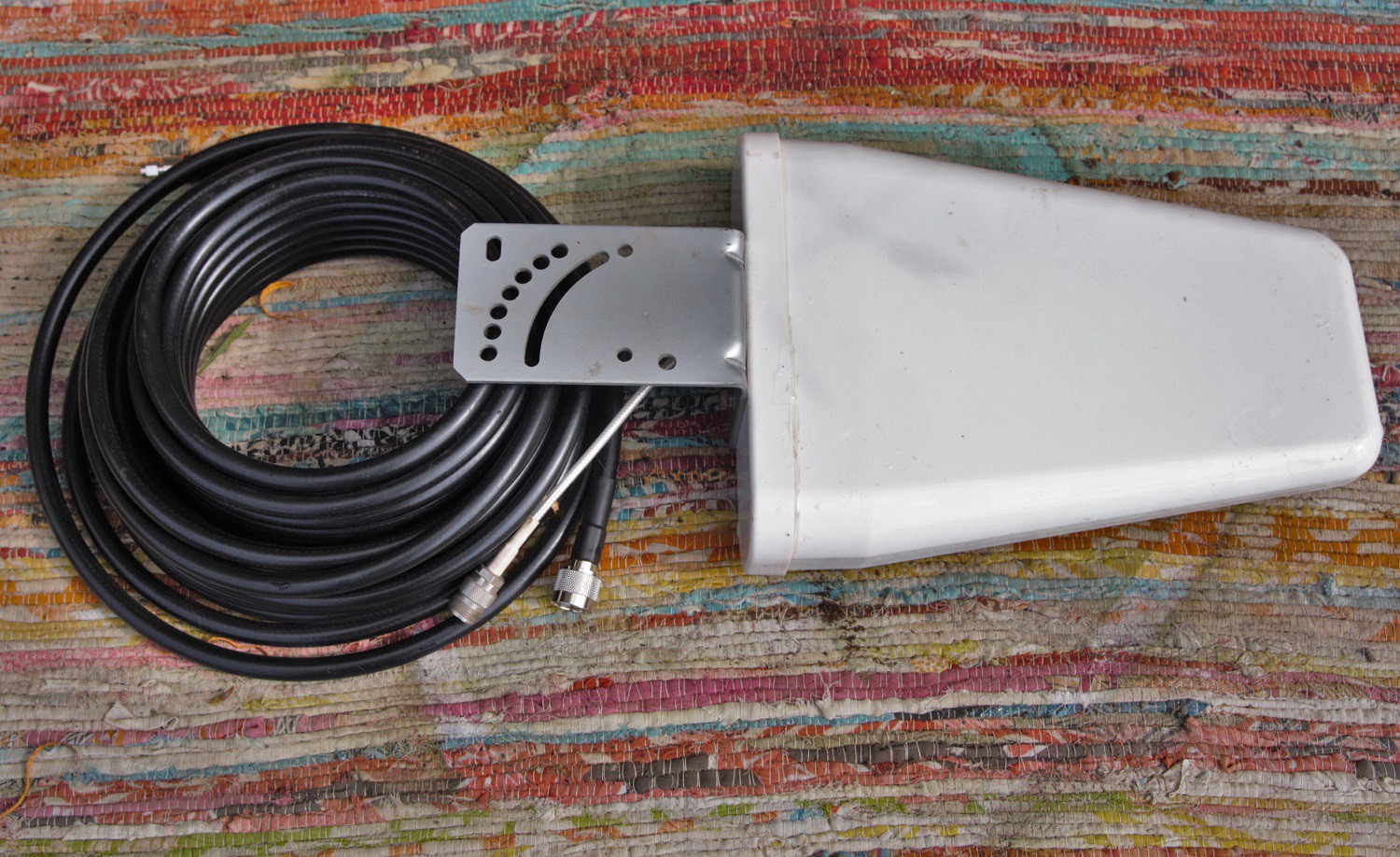 The cable should be rated to 0.3 dB loss per metre or better and the antenna should be a Yagi type with performance of 6dB or better. The antenna should be at least 20' in the air, or higher depending on location, and should be pointed directly towards the nearest local 4G transmitter - this can be done by trial and error by swivelling the antenna around and monitoring the results on the SDR.
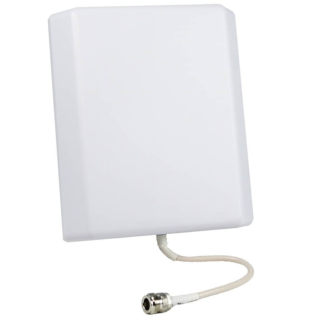


 Martin
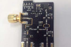
 Igor Brkic
 Phil Handley
cancer in package