 Antonio Regueira
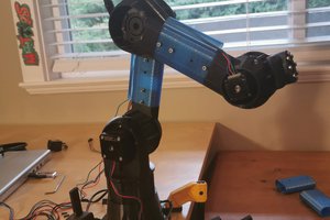
I want to do this project because I´ve been studying a lot of robotic arms but I couldn´t find one with enough strength, accuracy and low price, so I´ve decided to build one.
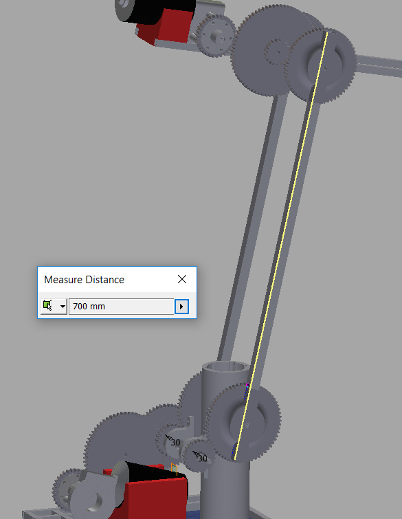
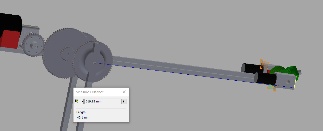
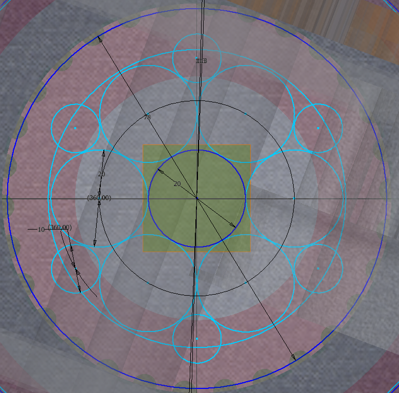
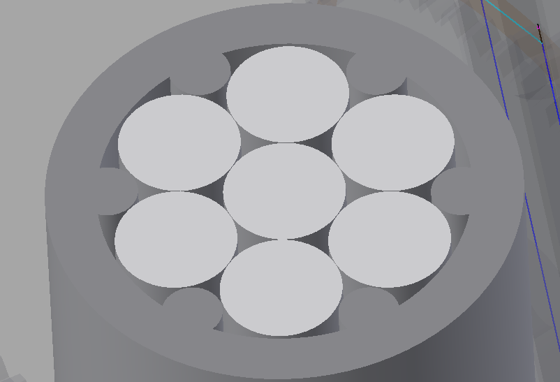
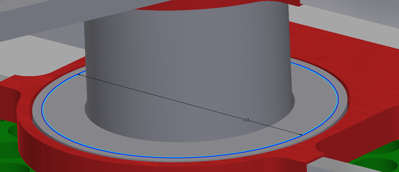
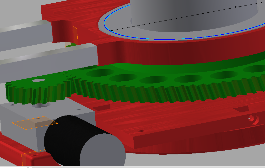
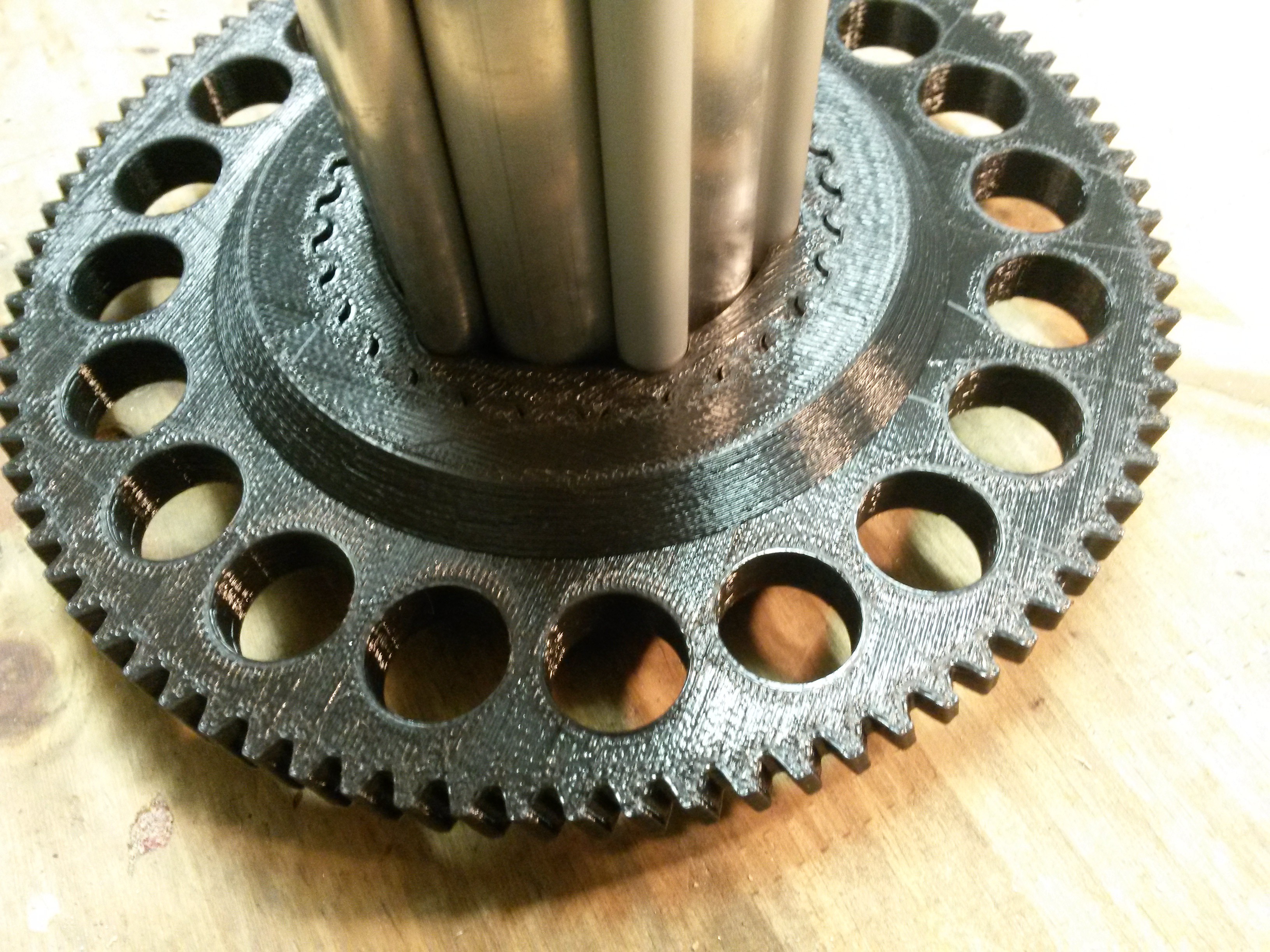
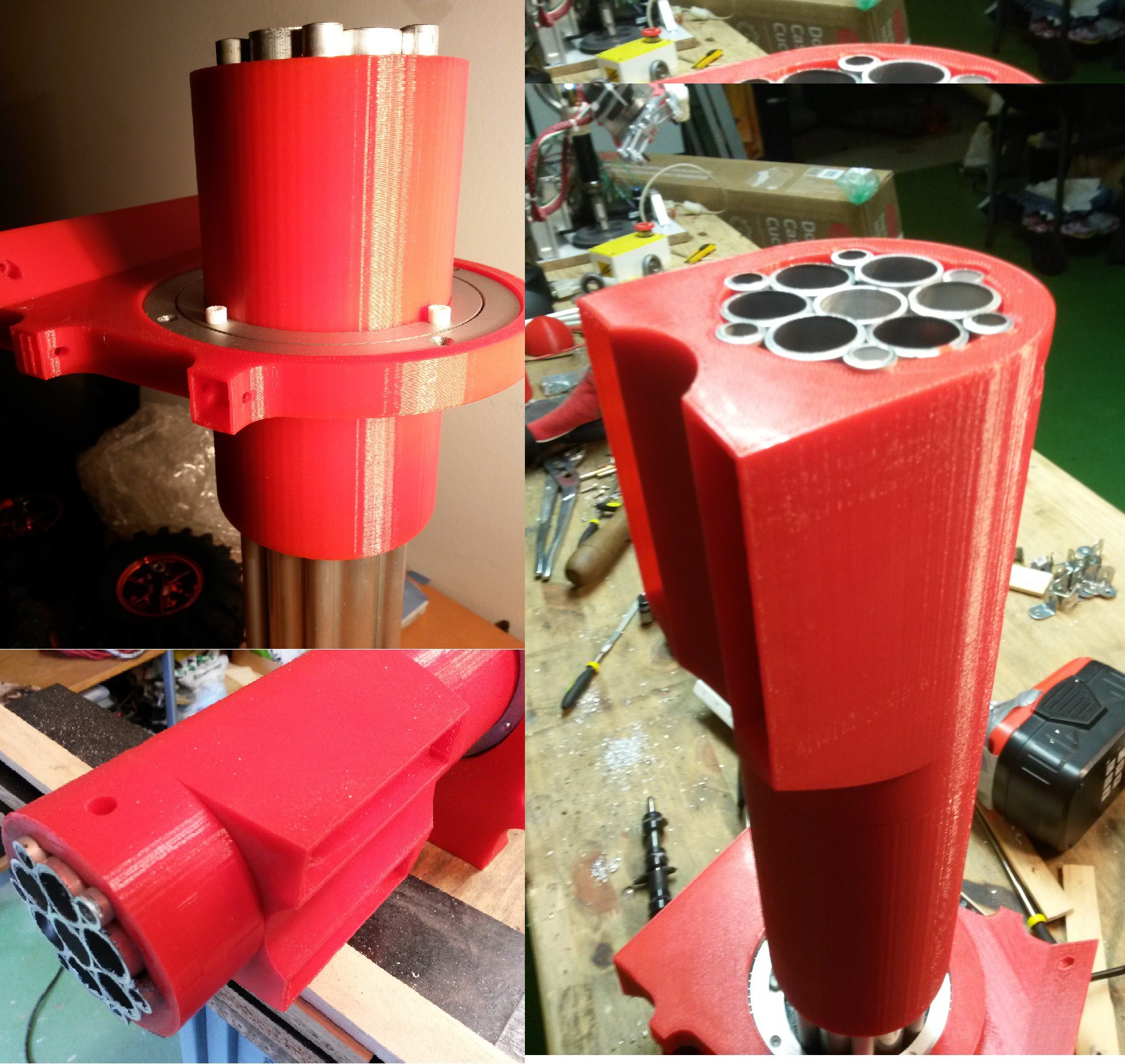
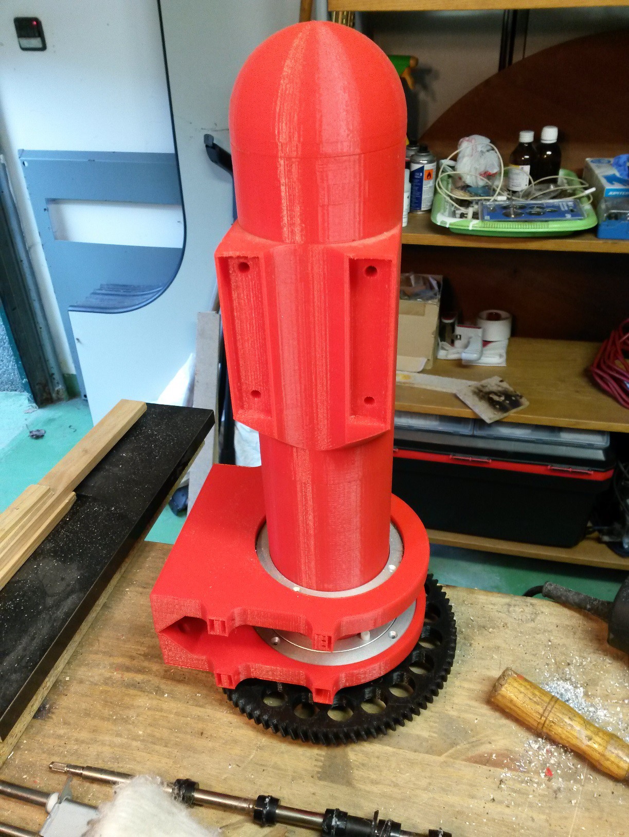
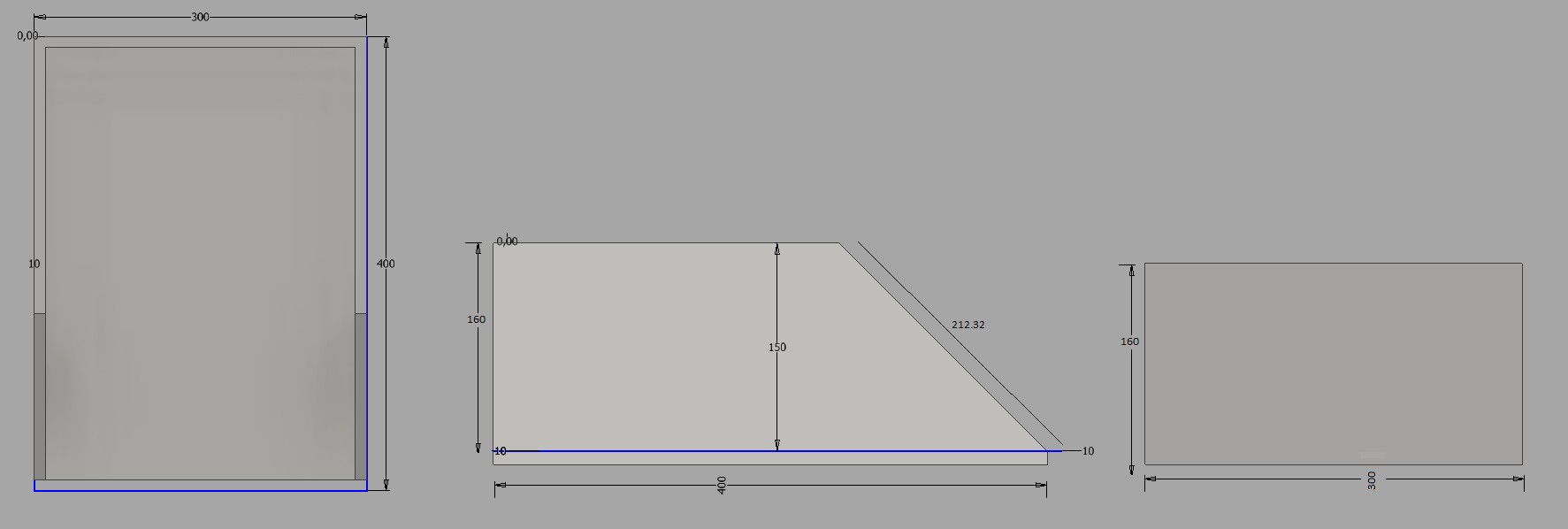
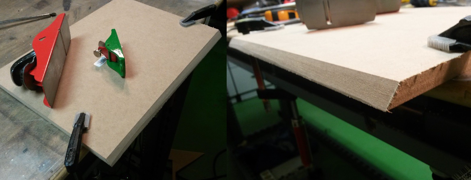
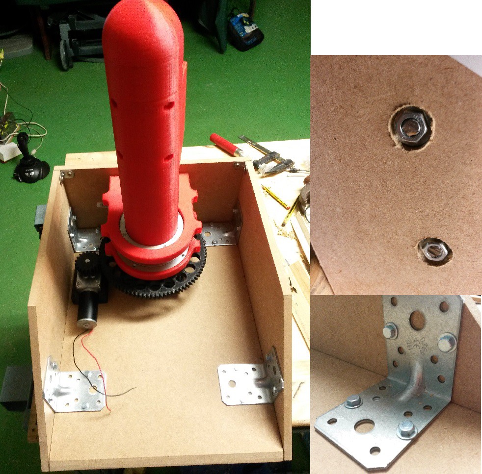
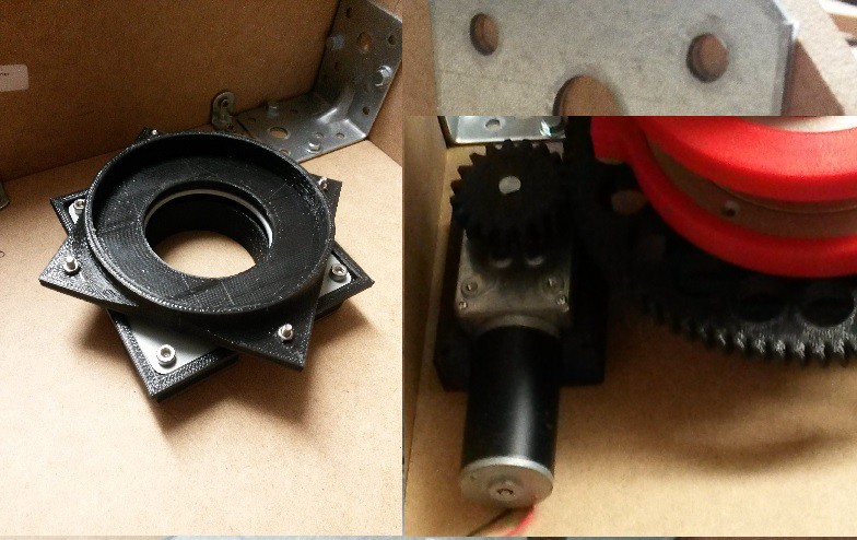
I have experience designing 3d printed gears and I know that it can hold a lot of efforts, so I’m designing all the mechanical structure using aluminium, iron and 3d printings. I´ve studied the mechanical properties of square aluminium profiles and I can use them with having nothing to worry about; aluminium is cheap and it can be found in such a lot of shapes. The main problem was to make a central axis to hold the horizontal efforts of the rotation of the base, but as you can see at one of the logs I solved this problem joining 13 cylindrical profiles. I selected a 16x16mm square profile to make the structure of the arm and forearm. I made some tests and it can hold perfectly the weight without bending.
The accuracy in a 1.50 meters robot arm it's a big problem, as I studied in some subjects like control engineering,I can make a perfect closed loop system with a PID error control. Other way to improve the accuracy is to make the robot arm slower, but if we do that, it will take an eternity to go to the final position, so the accuracy of 0.1mm will lose part of it sense. So I have to look for a mid-solution between accuracy and speed.
I want to control it with an FPGA, I know that it's a very hard work but I started at college with this boards and I think that they are amazing. Additionally, if I can do a good description program it will be faster and better than an Arduino program. It´s true that at the beginning I will start using an Arduino Mega because is easier, but once I finish the hardware I’ll start with the FPGA control.
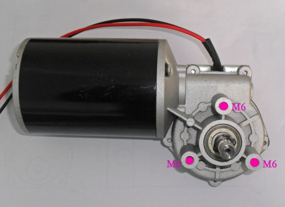
All the sensors will be optic encoder, because I´ve used potentiometers at the other robot arm and I had some problems like low accuracy reads and difficulties to make a stable voltage level. I’m searching several models, with a variety of resolutions, and the fact is that in some parts is better to pay more and have an absolute encoders rather than having to make a homing every time a switch on the robot.
I'm designing as fast as I can but I have to study and work in other projects. Anyway, I really hope to have it working perfectly at the end of this year.
So I’ll be publishing all the improvement and steps with tons of photos, sketches and videos. If you like this project, please follow me to see all the entire process.
All the 3D files are in autodesk inventor and FreeCad compatible format (.stp)
See you soon!
This is the last goal i achived:
I had to pause this project because of the engineering i'm doing, as soon as possible i'll continue


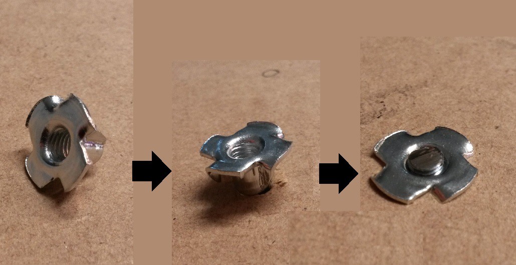
 So you must have something like this:
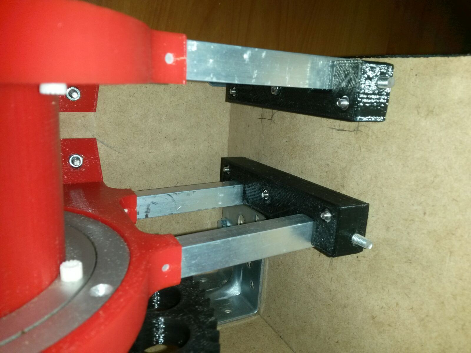
 Mattias
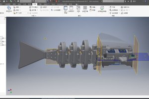
 Shuang Peng
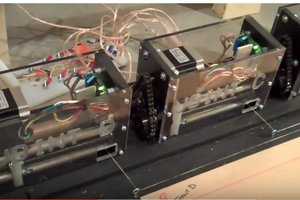
 Tom
Tom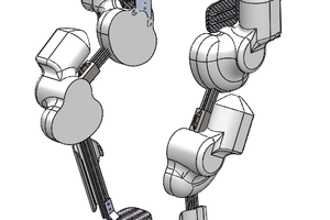
 Guillermo Herrera-Arcos