Close
0%
0%

Trixel LED

Interactive LED Kit

Similar projects worth following
Trixel LED is an interactive LED kit,
Create your own interactive Light elements by soldering basic shapes, such as triangle, square, pentagon and Hexagon. to create an interactive LED sculpture.

Project status:
stage 1 - complete
Explore shapes for basic LED elements. design pcb`s for simple controller and LED`s.
stage 2 - Process
Design LED diffuser for each element.
stage 3 - Ideas
Improve Electronics to include sensors for interactivity. Accelerometer, Gyro, Magnetometer, Microphone, Motion / Distance, BLE - Communication, Battery.

Design materials are released as the project progresses through various links.
GitHub : https://github.com/arkadiraf/Trixel-LED

Project Links:

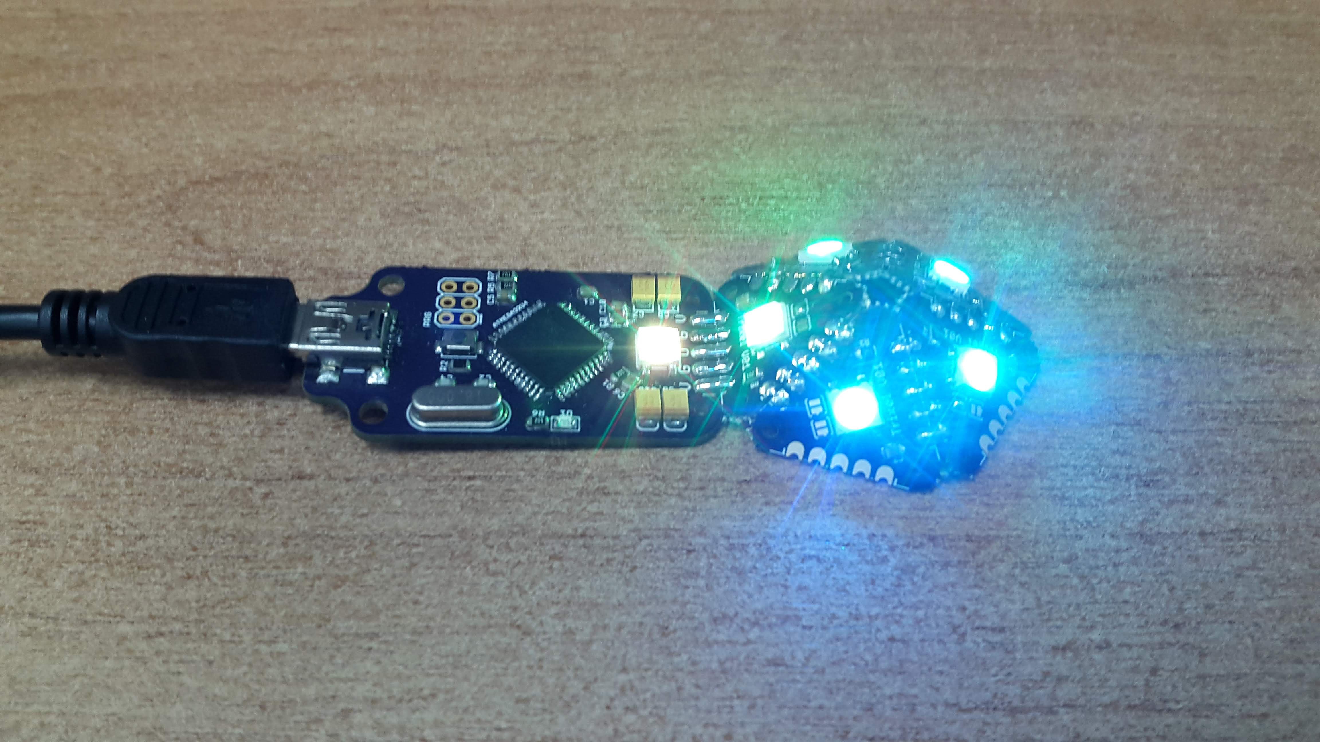
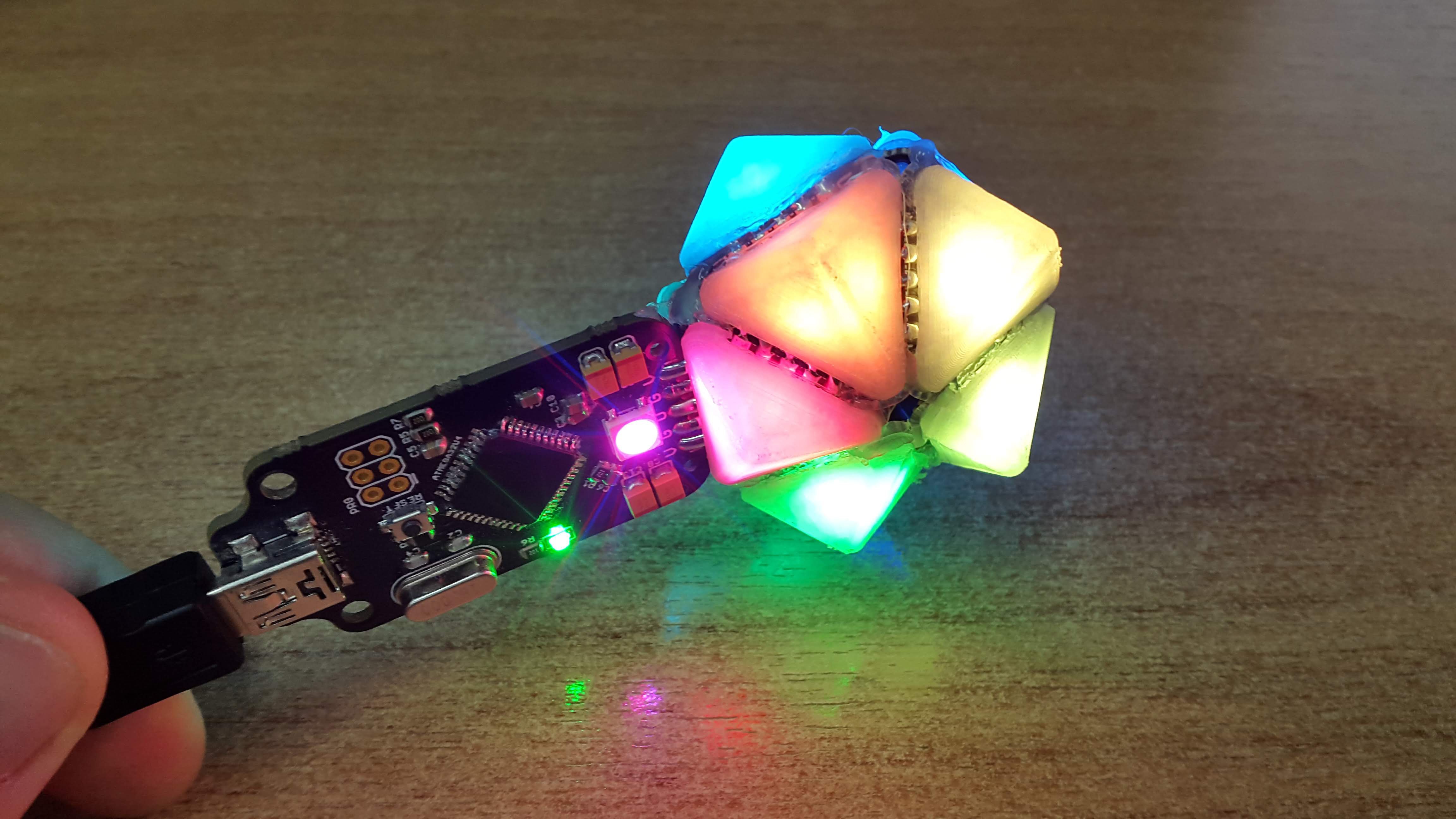
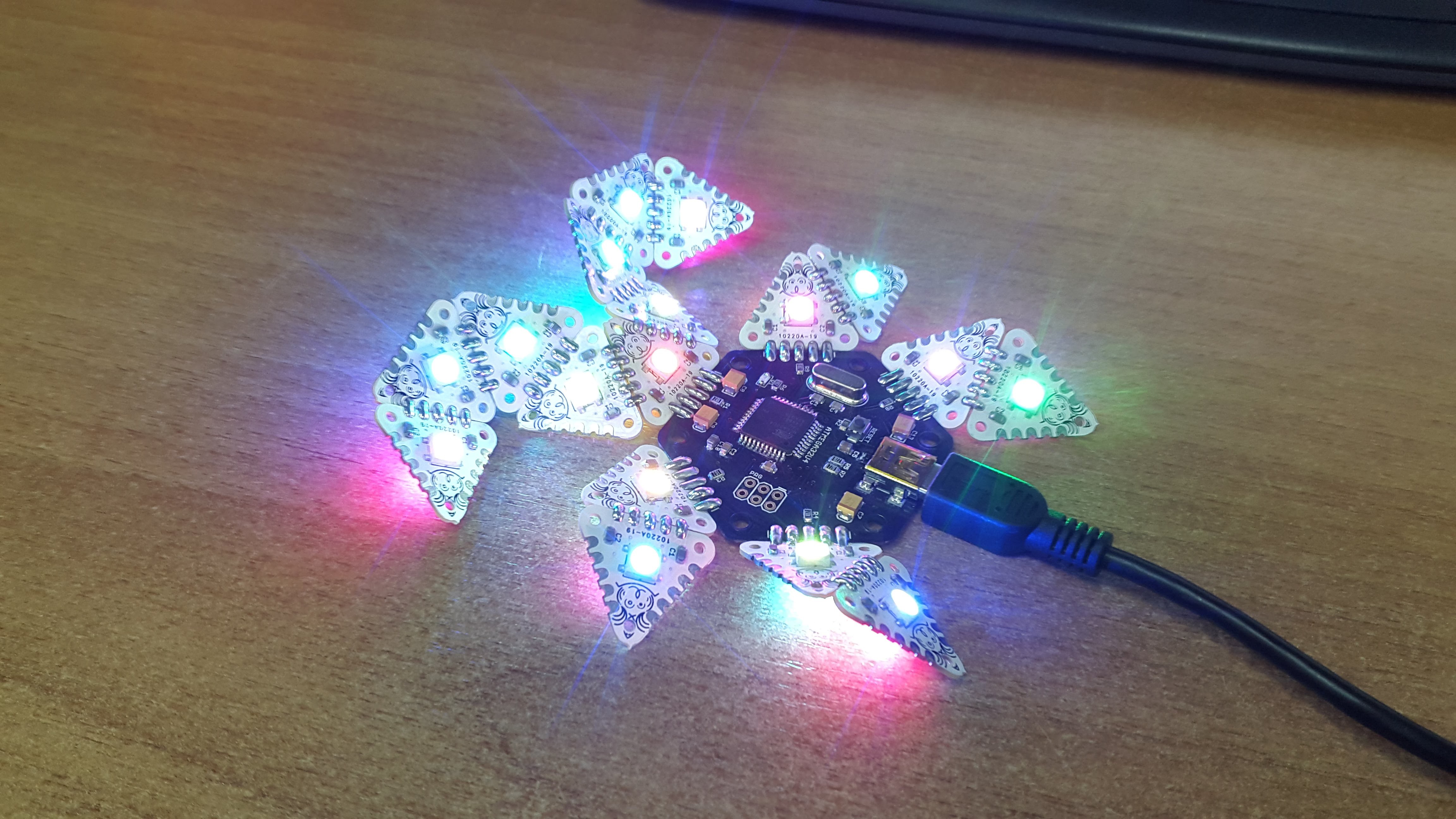
Youtube Simple MCU with triangles:

OSH Park Circuit Links

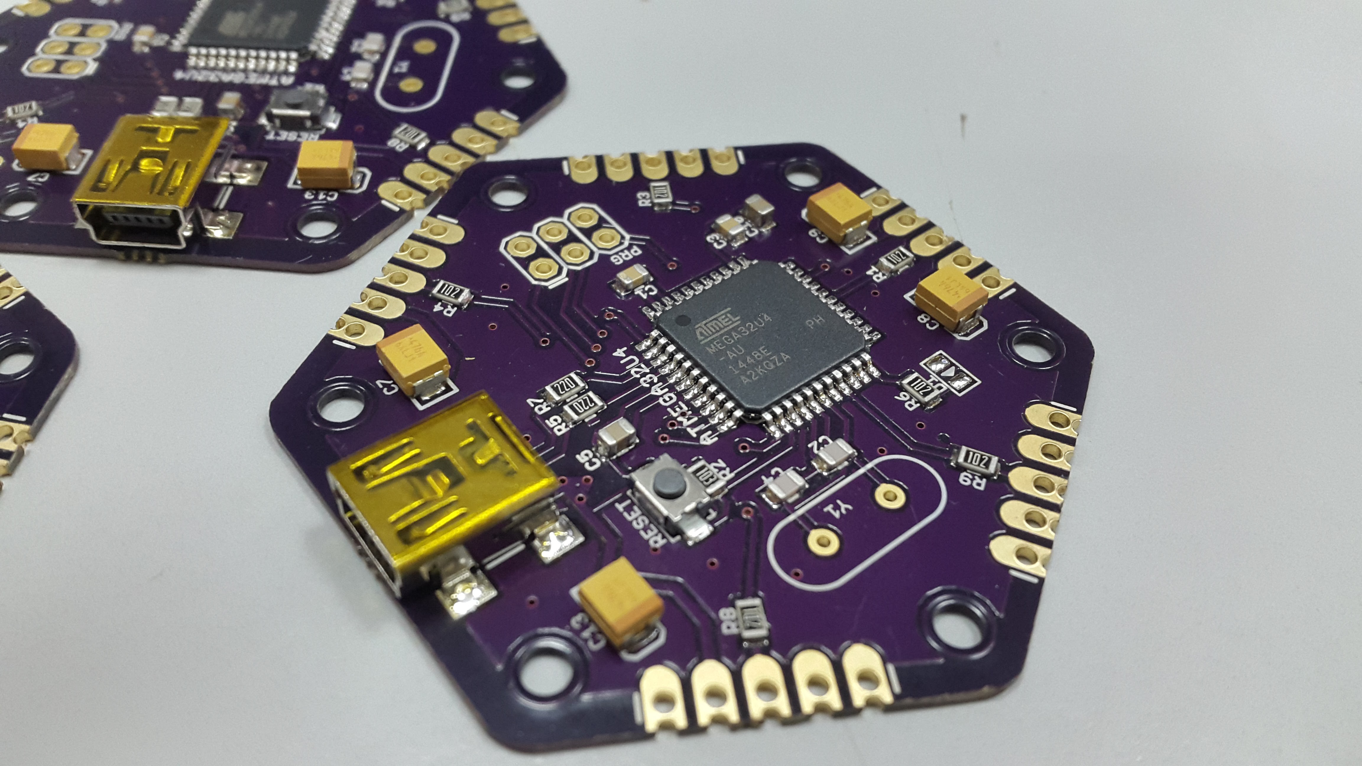
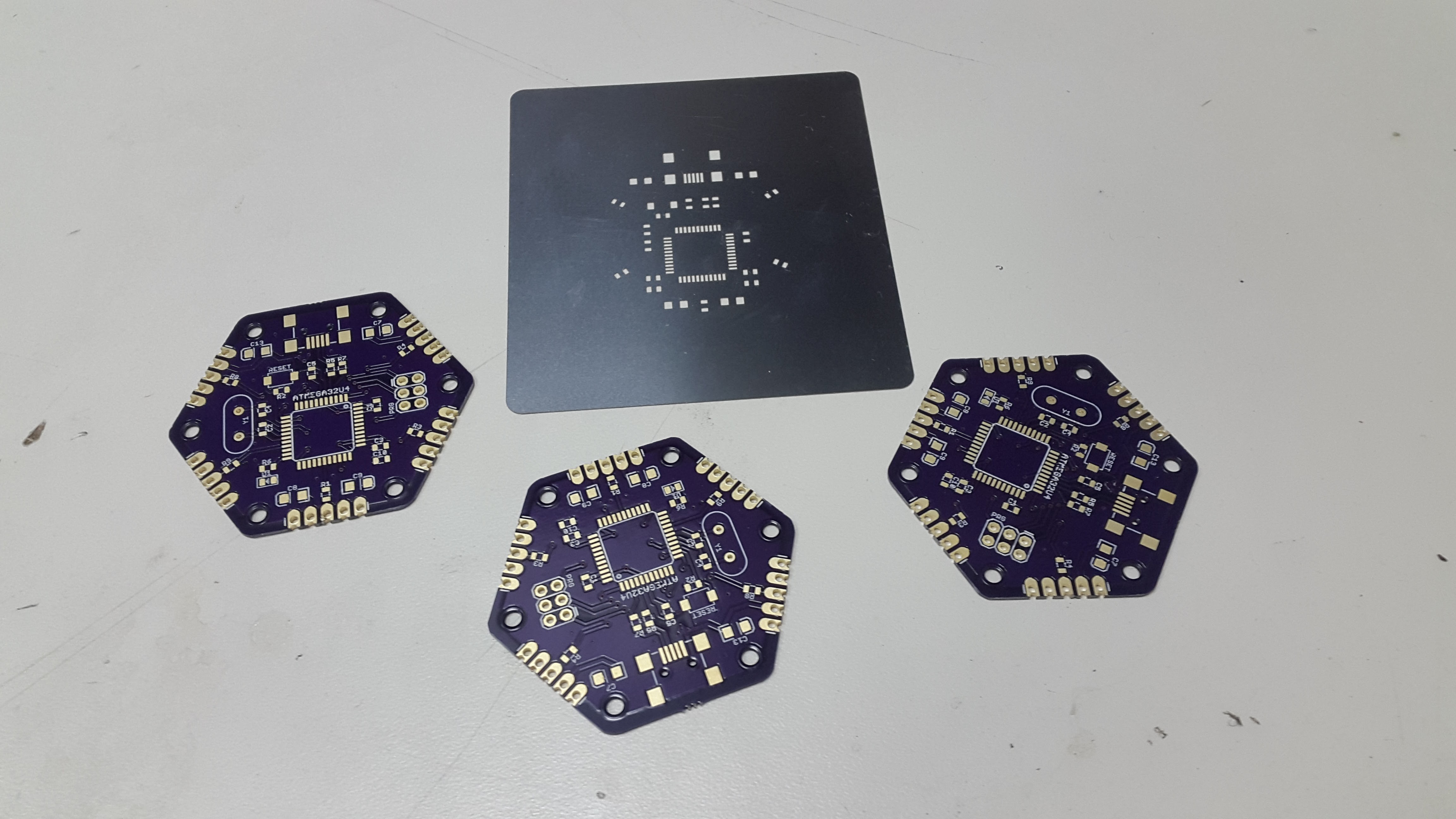
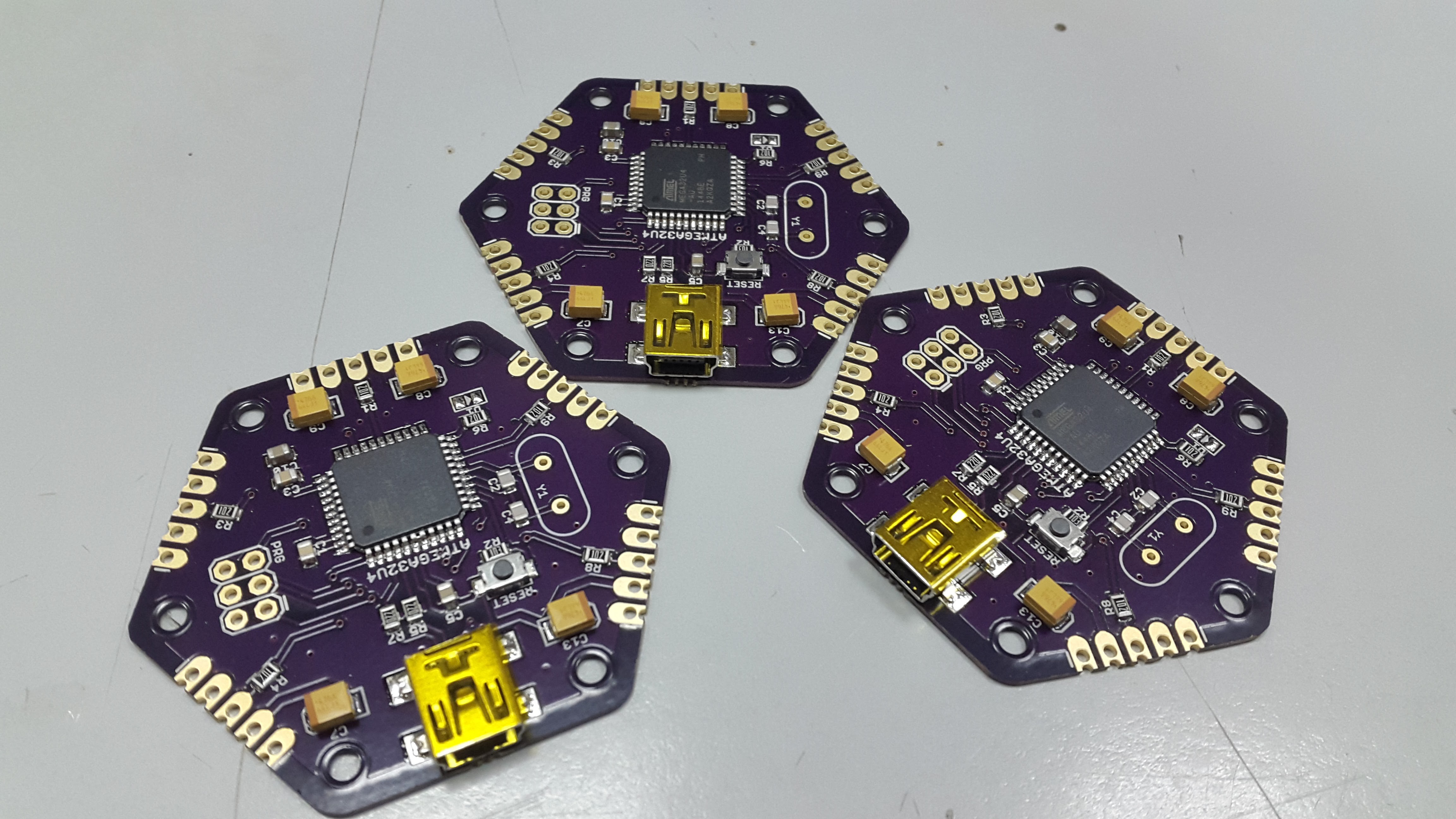
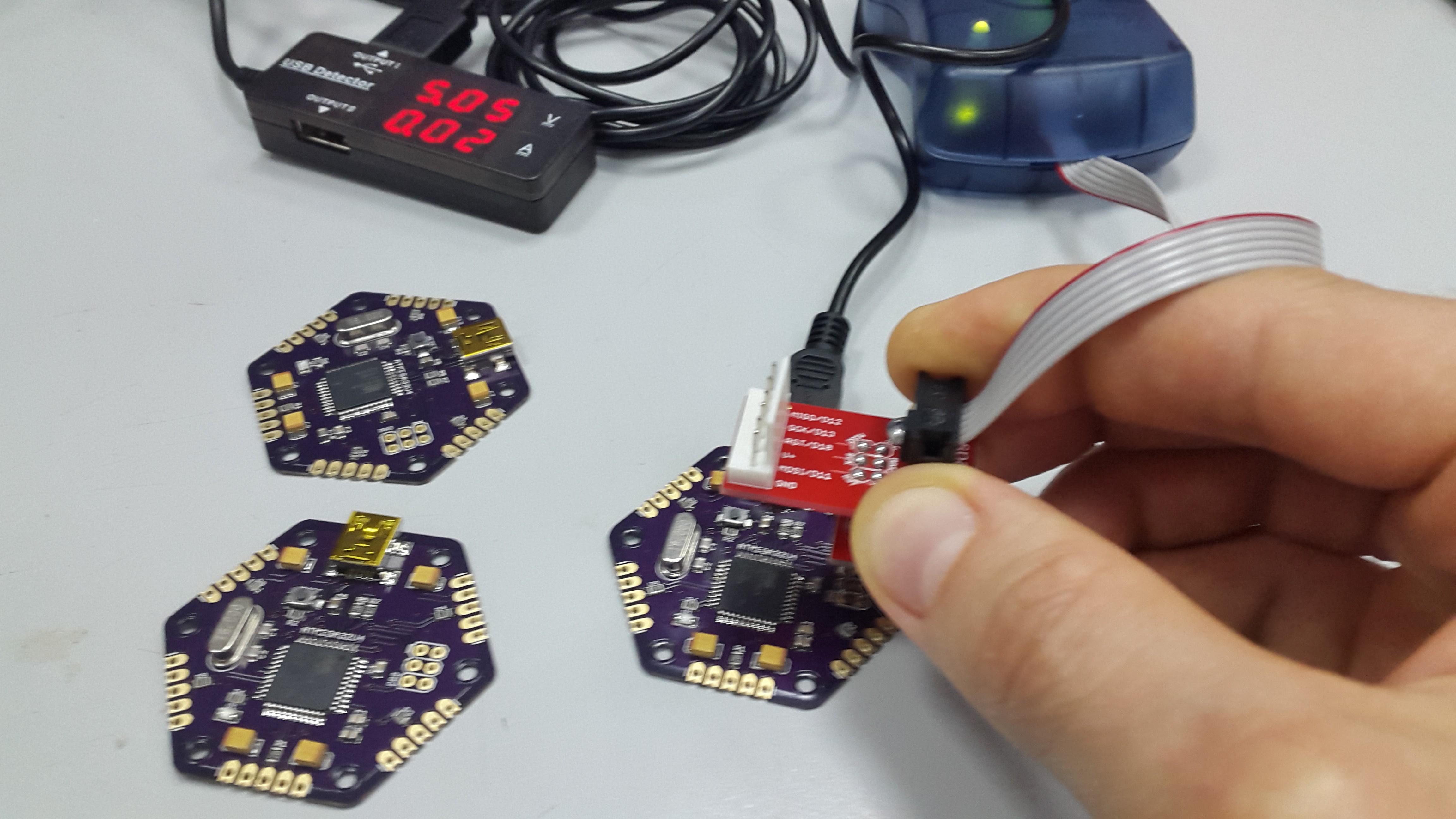
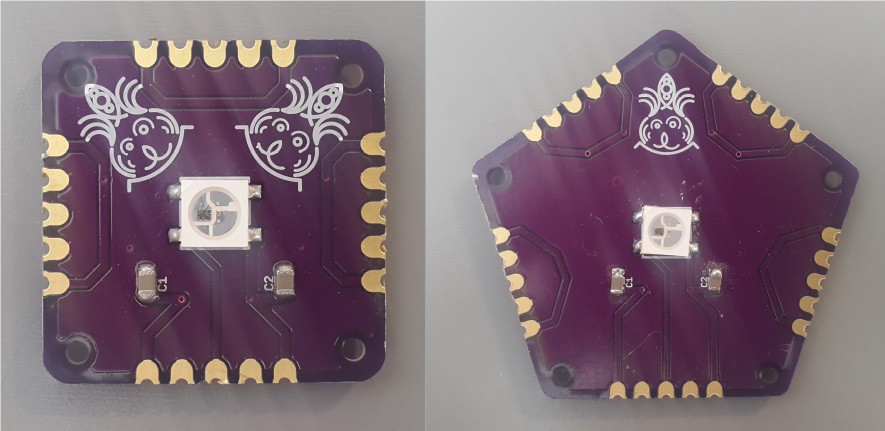
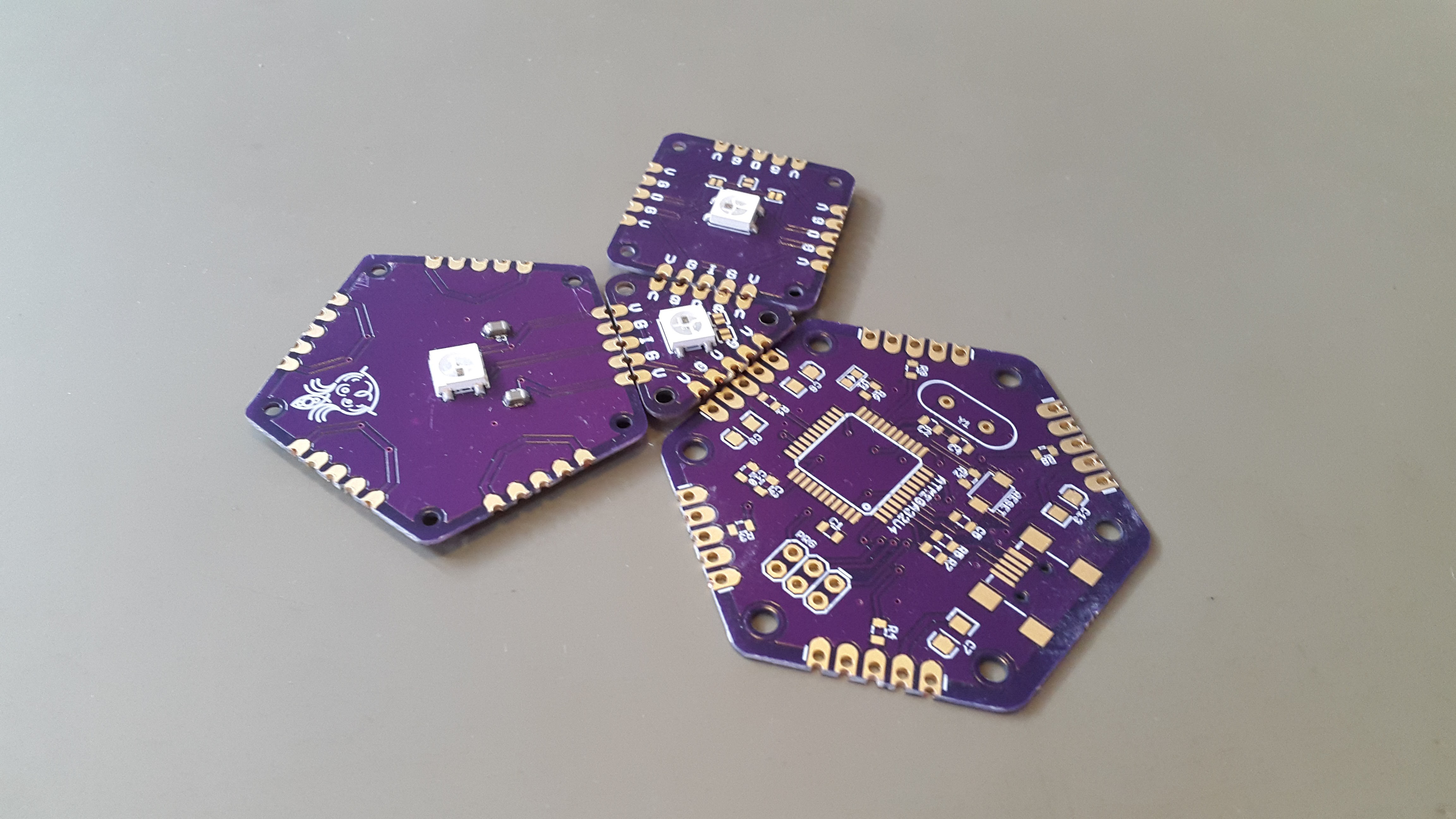
Hexagonal MCU : https://oshpark.com/shared_projects/xangB68O

Pentagon LED : https://oshpark.com/shared_projects/5bxh1ML1

Square LED : https://oshpark.com/shared_projects/2S5FQ5g4

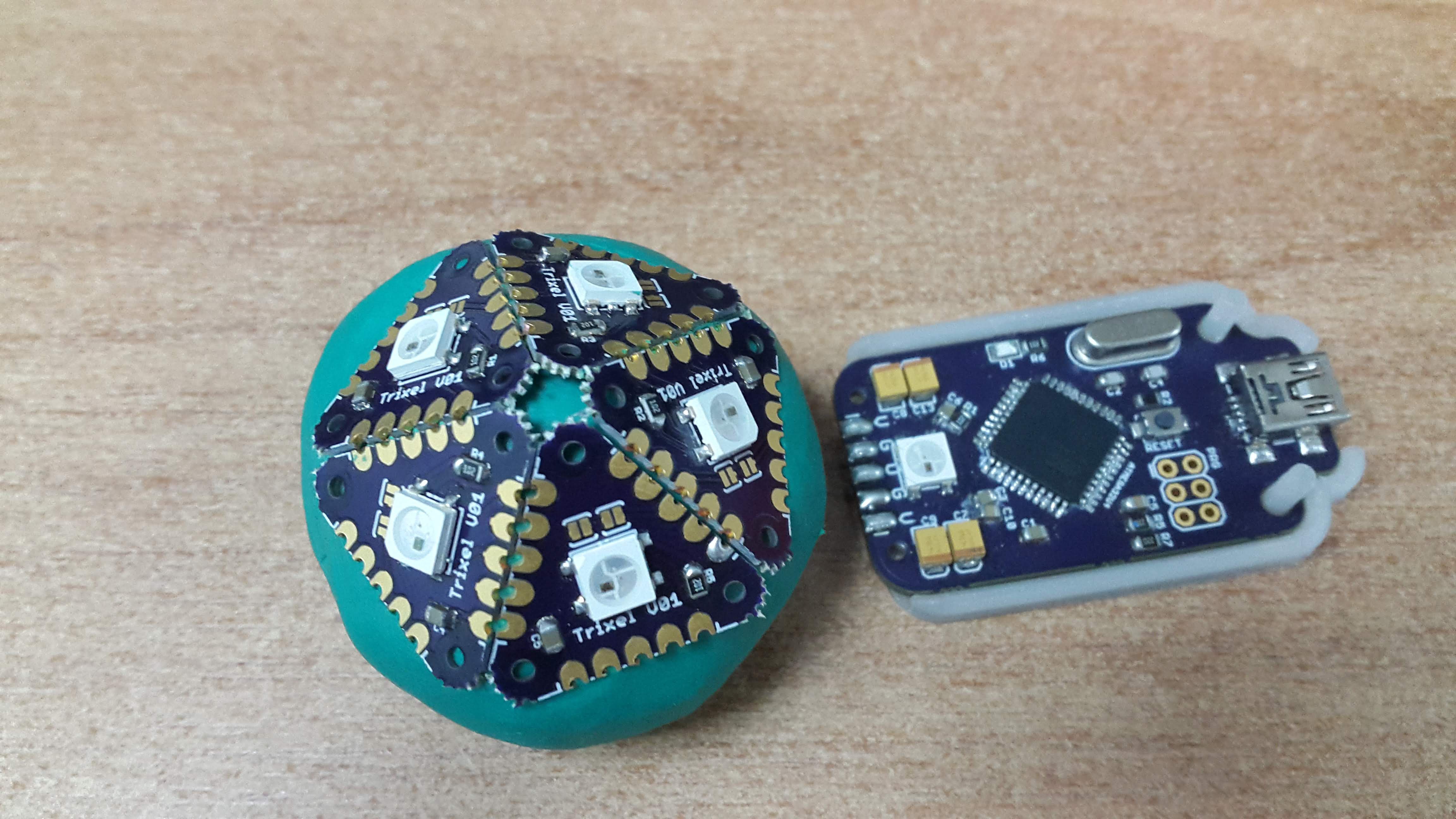
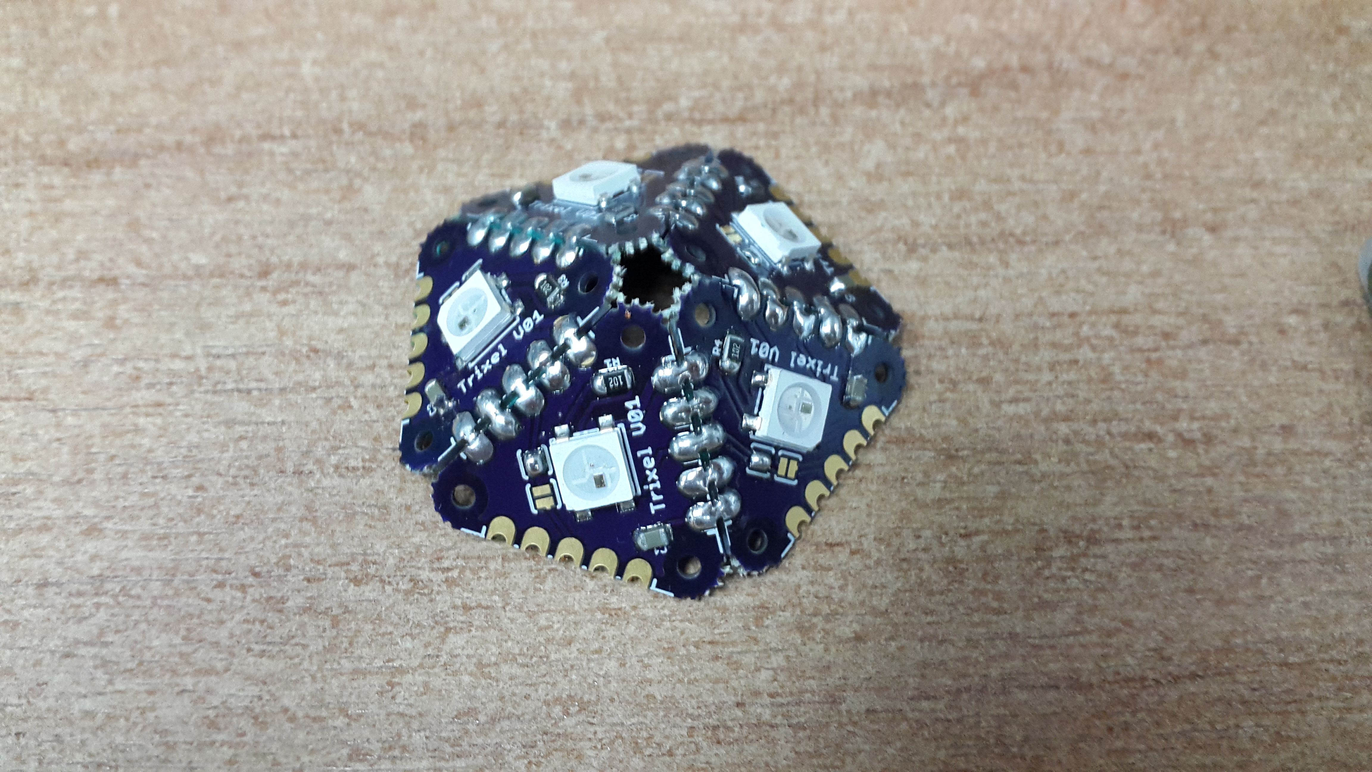
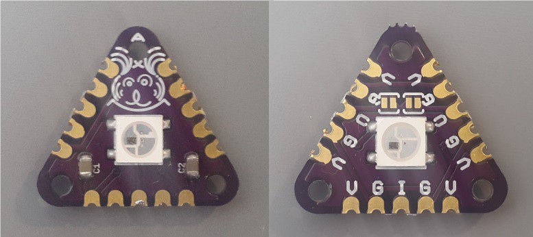
Triangle LED : https://oshpark.com/shared_projects/3ms9FD8s

Simple MCU : https://oshpark.com/shared_projects/gn4UkQom

Panels

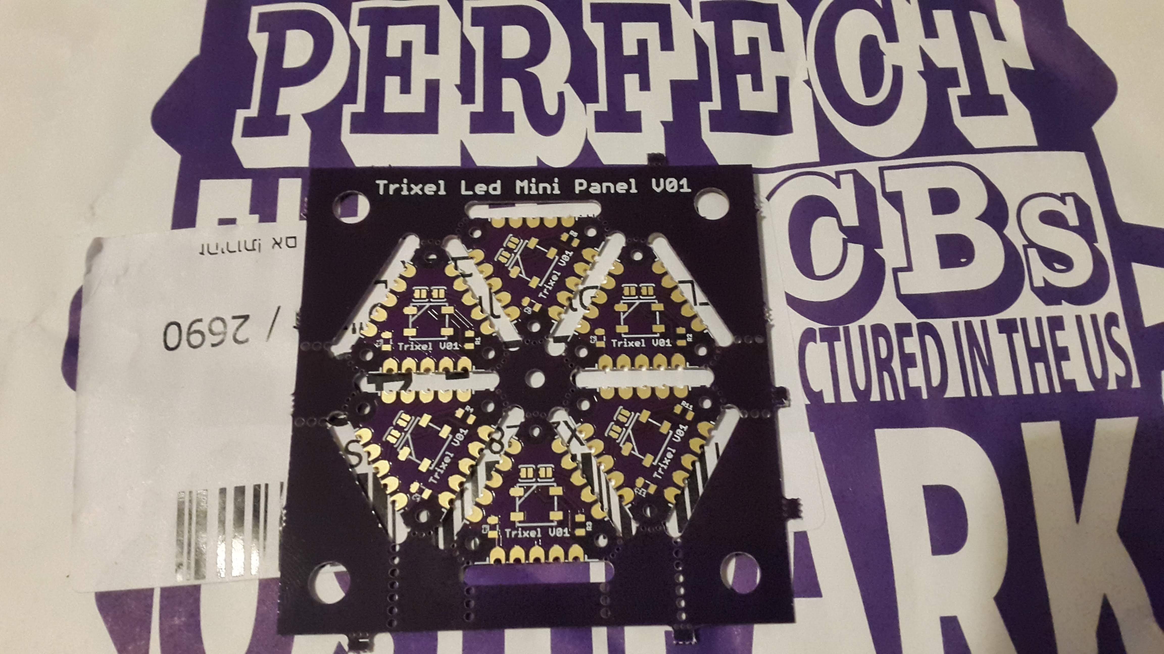
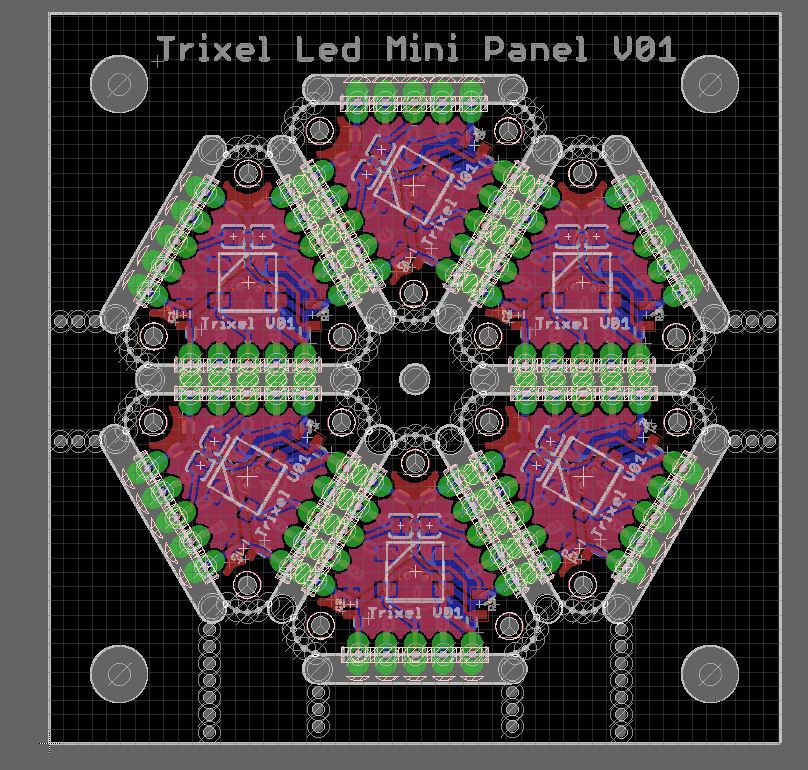
Trixel mini Panel V01:  https://oshpark.com/shared_projects/wMtWZjMH

  • 1 × Atmega32u4 Microprocessors, Microcontrollers, DSPs / ARM, RISC-Based Microcontrollers
  • 1 × WS2812B
  • 1 × https://oshpark.com/shared_projects/xangB68O MCU Hexagon Circuit - Not tested yet
  • 1 × https://oshpark.com/shared_projects/gn4UkQom Simple MCU circuit
  • 1 × https://oshpark.com/shared_projects/3ms9FD8s Latest triangle Led circuit

View all 8 components

  • Trixel LED Mini Panel V01

    Arkadi05/25/2018 at 10:18 0 comments

    After assembling a few dozen of Triangles / Square, I figured its time to design something more easy to assemble. First conclusion was that a led at both sides may be fun, but is much harder for production either by hand or by machine. So the first move was to design a single side led elements.  (Available on GitHub ). For the second conclusion i figured its time to work on paneling the elements, so that the assembly process will be on multiple boards simultaneously.

    As for the elements, I have learned a bit more proper design and implemented that in the new files, making the design a bit cleaner, and implementing a small robustness in the circuit by adding a limiting resistor for each led output. in order to help saving the led in case of shorts for the output. In addition the transition to single side leds allows soldering 2 boards back to back, and by that increasing the flexibility to route the leds in different directions while keeping the option for leds on both side of a pcb ( making a thicker PCB).

    Creating a good panel requires some experience, and for that I am highly grateful for the huge amount of feedback and suggestion I got from Dan at OSHPARK He definitely saved me several iterations. From the experience I can provide my two cents for paneling a PCB.

    There are various documentations as for how to make a panel and the available methods, V - cut, stamp holes. milling etc. each manufacturer has it`s one requirements and before applying a design I suggest reading thoroughly the documentation from the specific manufacturer.

    Since most of my board has castellated holes, i chose to use the stamp holes method to separate the boards, easy said hard to implement. Since there are various requirements for stamp hole diameter and the distance from the holes which will influence how easy the boards will be separated while not falling apart during manufacturing. OSHPARK has a great documentation for that with a few suggestion.

    My work method iclude working both with eagle and fusion360, since autodesk has bought eagle the programs are becoming more "friendly" with each other. I start designing with fusion360 since you can make the design parametric and easy to change.

    After some experimenting and attempts, I have chosen stamp holes at 0.02in (0.5 mm) diameter, and at a distance of 0.04in (1 mm). positioning them on the outer edge of the board. The milling space was set to 1 in (2.5 mm).  The design results looked like that. (and available here: Trixel Mini Panel Fusion360)

    From here I export the design as a dxf file to be imported into eagle. One for the stamp holes position which are implemented for the elements, and another for the panel file which should be the dimension layer in eagle. since the eagle import dxf isn`t perfect, some manual fixes are required. Here is the result after duplicating the triangles into the panel file.

    In order to be able to separate the boards from the panel some stamp holes were added allowing to break the panel. ( Thank you Dan , you have definitely saved me an iteration here). The Panel stamp holes are a bit larger, 0.4 in ( 1 mm ) at a distance of 0.6 in ( 1.5 mm ).

    Breaking of the boards out of the panel is highly satisfying :)

    The separated boards look awesome and now it is the time to make something of them. 

    I have decided to make a closed shape out of the new triangles, and the easiest is 2 half's of 5 triangles each.

    Adding some diffuser elements:

    And that is how it looks

    Some conclusions:

    - Assembling a panel is way way faster. especially applying the solder paste.

    - The boards snap out quite easy, but i would suggest a bit larger stamp holes for the triangles or positioning them a bit closer. I think this is something which is needed to be discussed with the manufacturer since not every design is acceptable. The risk that the elements will break...

    Read more »

  • Hexagonal MCU

    Arkadi03/26/2017 at 15:32 0 comments

    The first MCU iteration i have tested out was a simple bar, (simple mcu) but after exploring the additional shapes. I have decided to make the MCU as the hexagon shape, since its the repetitive shape of 6 Triangles. 

    As you can notice I have ordered the pcb`s from OSHPARK (Perfect Purple PCB) ,  and since discovering how easy it is to assemble boards with a reflow oven, I have added the little bit for a stencil from OSH Stencils.

    From there it is as easy as baking a sponge cake.  Apply some solder through the stencil, populate the components, 7 minutes in a reflow oven, adding the through hole components by hand ( the crystal ).

    And wallha, you have 3 beautiful custom made boards to play with.

    Since it is an open source project, and i am using one of the most popular MCU`s at the DIY market, The atmega32u4, I have allowed myself to flash the arduino micro bootloader on the mcu.  With the help of the avrisp mk2 programmer and a small adapter board by sparkfun - ISP Pogo Adapter. The pogo pins are very helpful when you don`t want to add unnecessary headers which don`t have any use besides a one time flash of the bootloader.

    The boards are ready.... Arduino compatible, and programmed as any arduino pro micro compatible board out there,  but in your custom favorite shape.

    To test the new boards i have modified a bit the sample code by adafruit ( neoPixels - strandtest ) to work with 5 strands with the addition of some comments to the bootloader and fuses used -  strandtest.

    After soldering some triangle shaped leds you get a highly satisfying, custom made 3d light fixture :)

  • The Idea & How it started

    Arkadi03/21/2017 at 14:32 0 comments

    Idea:

    The idea is designing basic elements of addressable LED`s which can be combined into fascinating shapes.

    I play a lot with LED`s, mostly the famous addressable LED`s such as the ws2812.

    [ Sample projects: https://hackaday.io/project/5466-smart-juggling-balls , https://hackaday.io/project/6039-shakeit, https://hackaday.io/project/7430-chess-timer, https://youtu.be/fSF5rG59FKs . ]

    You can get the LED`s in various forms such as strips, circles , Matrixes, bars, (Adafruit has a wide variety of shapes) or you can get them in SMD to design your own two dimensional shape.

    Images from: https://www.adafruit.com/


    Mostly the forms aren't designed to be soldered together directly, you can solder wires between them but not to create a stand alone form.

    Based on this Gap my concept started to formalize.


    Design Process:

    I have started my design iterations with a simple triangle as a standard base element and hence the name, Trixel - Triangle Pixel:

    Later on i have extended the design for a square and a pentagon shapes while maintaining a few guide lines for compatibility between shapes.

    Design rules:

    - Equilateral shapes, side length 1 inch

    - Side connector is a symmetric (V G S G V) 5 pin castellated, spaced at 0.1 inch

    - One middle LED

    - One input, the rest are potential outputs

    Design files (Eagle) are available on GitHub: Trixel-LED

View all 3 project logs

Enjoy this project?

Share

Discussions

Andrew Bolin wrote 04/05/2017 at 23:06 point

Well, I was just working on the layout for practically the same thing (the triangle one)... Maybe now I'll just buy yours instead.

  Are you sure? yes | no

Arkadi wrote 04/06/2017 at 06:55 point

That`s usually what happens :) I was surprised that i didn`t find projects as this one on the web when i started. I did find some constructions using LED`s but not Kit oriented.

The project is open source, so now you can invest your time to develop it into some new direction or add to it your own designs  / idea`s. :)

All files available on GitHub, you are welcome to fork it and share where you go with it.

  Are you sure? yes | no

Andrew Bolin wrote 04/06/2017 at 08:28 point

Legend! I didn't see the github link before. I'll see if I can convert it into Kicad and get a batch made up, will be sure to give you credit when I win the local electronic art prize ;)

  Are you sure? yes | no

Arkadi wrote 04/06/2017 at 08:30 point

 you can ordered tested circuits from OSHParks, i did the prototypes iterations with their service.

  Are you sure? yes | no

oshpark wrote 04/04/2017 at 05:46 point

Awesome project!  We look forward to future updates

  Are you sure? yes | no

Arkadi wrote 04/06/2017 at 06:51 point

Thanks, hope to have some time soon to assemble the next MCU module (Hexacon) and post a few more LED fixtures.

  Are you sure? yes | no

carltech2000 wrote 03/27/2017 at 21:33 point

how difficult would these be to use l.e.d.s in the "grow" spectrum?

  Are you sure? yes | no

Arkadi wrote 04/06/2017 at 06:50 point

I am planning to make a Glow Plant (building a construction around a plat pot) But its not considered as grow light as you need specific spectrum of light. you can easily design pcb`s for the desired  grow LED`s but its not exactly the point of the project as the light fixture won`t be interactive. (I use addressable LED`s so you can change the light of each pixel in the chain).

  Are you sure? yes | no

bobricius wrote 03/25/2017 at 23:11 point

Great idea, I created paper ball model from 12pcs penagonal boards ... look very good ;)

  Are you sure? yes | no

Similar Projects

Does this project spark your interest?

Become a member to follow this project and never miss any updates