In Log(1) I checked the impact of using retroreflectors. As the plots of the DSO were not really as expected I got some doubts about the possible signal quality can be achieved.
The response of the receiver shows rather an “edge-something” than a proper signal which leads to questions about the potential bandwidth. I used for this test a Cds photoresistor these photoresistors have a good sensitivity but the datasheet says that they have with 20ms-30ms terrible rise and fall times. This explains the measurement pretty well but also proofs the impossibility to use them for such an application.
I assume a photodiode would work much better for this purpose. As I hadn’t any I’d remembered that a LED in reverse operation should do the same function as the theory says. But that’s theory and I couldn’t make it happen, so back to the visibility proof on paper.
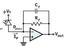
Reaching high bandwidth with optical receivers is general no question as fiber optic receivers can operate with some GB/s. The question is whether and how this is reachable for a maker at low cost. An optical receiver in the communication uses often a TIA (transimpedance amplifier) to amplify the signal coming from a photodiode (PIN-Diode).
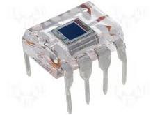
Such a combination of TIA and PIN-Diode is available with the OPT 101 (a transparent integrated circuit) – which would be the easiest way. In such a configuration the “gain” is defined with the Rf as Vout = Rf * Iin. Therefore the OPT 101 has an integrated 1M resistor which can be connected in the feedback loop. With this default wiring, the arrangement would achieve a bandwidth of 14MHz which isn’t sufficient as the LRLS require a bandwidth of about 100-200MHz for a 5m distance (without retroreflectors). The Op-Amp theory allow to achieve a 10 time higher bandwidth, if the gain is reduced by the same factor (as long the Op-Amp can do it) - which means in this case to use RF=100k instead.
This isn’t confirmed by the OPT101 datasheet. It predicts only a bandwidth of 44kHz in this case. But the limiting factor isn’t the Op-Amp, it’s the PIN-Diode as it has a high capacity of 1200pF.
Back to square one we need a PIN-Diode with a fairly low capacity and a reasonable fast Op-Amp. To calculate the bandwidth in a close formula isn’t that simple but I found an estimation in one of TI’s application note. (GBWP = gain bandwidth product)
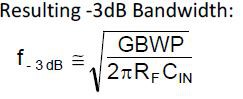
If a fast Op-Amp is used (like e.g. the OP 37) the major impact comes from the PIN-Diode capacity and the gain bandwidth product of the OP-Amp. An example of an easy to get and cheap PIN-Diode is the BPW34 with a capacity of about 40pF. A TIA arrangement consisting of a BPW34, an OP 37 and an Rf = 1MΩ should provide a bandwidth of about 800kHz. This makes it visible to build an working receiver stage for about a dollar.
Discussions
Become a Hackaday.io Member
Create an account to leave a comment. Already have an account? Log In.
Have you considered using one of the TV remote sensors? They already have an amplifier and a frequency filter -- so they will only switch on when they get light that is modulates at 38kHz. You can easily modulate your laser beam at that frequency -- this way you will be immune from noise from other light sources. And they are very cheap and easy to get.
A lens or even a small pipe should help with focusing the sensor on a small area too.
Are you sure? yes | no